Page is loading ...

PARTS, SERVICE
& REPAIR BULLETIN
PRESSURE REGULATORS
Manual No: 0056-2690
Issue Date: 22/2/2018
Revision: AB esab.com

!
WARNING
Read and understand this entire Manual and your employer’s safety practices before install-
ing, operating, or servicing the equipment.
While the information contained in this
Manual represents the Manufacturer's best judgment,
the Manufacturer assumes no liability for its use.
EDGE Series 2.0 PRESSURE REGULATORS
Operating Manual Number 0056-2690
Published by:
Victor Technologies Group Inc.
2800 Airport Rd.
Denton, TX 76208
(940) 566-2000
www.esab.eu
Copyright 2018 by Victor
All rights reserved.
Reproduction of this work, in whole or in part, without written permission of the publisher
is prohibited.
The publisher does not assume and hereby disclaims any liability to any party for any
loss or damage caused by any error or omission in this Manual, whether such error results
from negligence, accident, or any other cause.
For Printing Material Specification refer to document 47x1909
Publication Date: 2/22/2018
Revision Date:
i
Unrivaled Service and Support.
Every ESAB product is backed by our commitment to superior customer serviceod
and support. Our skilled customer service department is prepared to quickly answer
any questions, address problems, and help with maintenance and upgrading of
your equipment. Our products are backed with the most comprehensive warranty
in the business.
With ESAB, you can be sure that you have purchased equipment that will meet
your needs today and in the future. Product and process training is also available.
Ask your ESAB sales representative or distributor for a complete ESAB solution.

Be sure this information reaches the operator.
You can get extra copies through your supplier.
CAUTION
These INSTRUCTIONS are for experienced operators. If you are not fully familiar
with the principles of operation and safe practices for arc welding and cutting equip-
ment, we urge you to read our booklet, “Precautions and Safe Practices for Arc
Welding, Cutting, and Gouging,” Form 52-529. Do NOT permit untrained persons to
install, operate, or maintain this equipment. Do NOT attempt to install or operate this
equipment until you have read and fully understand these instructions. If you do not
fully understand these instructions, contact your supplier for further information. Be
sure to read the Safety Precautions before installing or operating this equipment.
USER RESPONSIBILITY
This equipment will perform in conformity with the description thereof contained in this manual and
accompanying labels and/or inserts when installed, operated, maintained and repaired in accordance with
the instructions provided. This equipment must be checked periodically. Malfunctioning or poorly maintained
equipment should not be used. Parts that are broken, missing, worn, distorted or contaminated should be
replaced immediately. Should such repair or replacement become necessary, the manufacturer recommends
that a telephone or written request for service advice be made to the Authorized Distributor from whom it
was purchased.
This equipment or any of its parts should not be altered without the prior written approval of the manu-
facturer. The user of this equipment shall have the sole responsibility for any malfunction which results from
improper use, faulty maintenance, damage, improper repair or alteration by anyone other than the manufac-
turer or a service facility designated by the manufacturer.
!
READ AND UNDERSTAND THE INSTRUCTION MANUAL BEFORE INSTALLING OR
OPERATING.
PROTECT YOURSELF AND OTHERS!


INDEX
Section Models
Page
1 ESS42
- i -
01
2 ESS32 20
4 Future EDGE Models --
3 ESS32-PFH 39

Delivery Pressure (PSIG)
Flow (SCFH)
1000 2000 3000
15
40
60
80
100
120
140
150
4000 5000 6000 70000
0
ESS42 Flow Data
Inlet Pressure (Air @ 70°F)
2000 PSIG
200 PSIG
Regulator Type
Delivery Ranges
Max. Inlet Pressure
Gauges
Standards Compliance
Other Safety
Flow Coefficient (C
v
)
Weight
Single Stage
15 psig (Acetylene), 60 psig, 150 psig
360 psig Acetylene and LP Gas,
3000 psig All Others
63mm/40mm ISO 5171 / UL Listed
& Recognized as Required
CGA E-4, UL 252, ISO 2503, AS4267,
ASTM G-175, Others (Depending on Model)
SLAM™ Impact Aborbing Safety Knob,
Self Reseating Relief Valve (Excl. Acetylene, LP Gas)
0.285
4 lbs Approx.
Materials of Construction
Body
Bonnet
Gauge Guard
Knob
Diaphragm
Seat
Inlet Filter
Forged Brass (CW617N per EN12165)
Die Casting Alloy No. 5, Conforming to ISO 301:1981 ZnAl4Cu1
Die Casting Alloy A380
High Impact ABS (Acrylonitrile Butadiene Styrene)
AISI 301 Stainless Steel
3000 psig Inlet Models - Urethane
Low Pressure Fuel Gases (Acetylene, Propane, etc.) - Neoprene
Sintered, Nickel Plated Bronze
- 1 -
ESS42 SECTION 1
TECHNICAL DATA:
SECTION 1
ESS42 Single Stage EDGE™ Series 2.0 Regulators
TECHNICAL DATA

ESS42
- 2 -
SECTION 1 GENERAL:
SERVICE & REPAIR – BEFORE YOU BEGIN
ESS42 Single Stage EDGE™ Series 2.0 Regulators
m WARNING! m
Apparatus improperly operated, maintained or repaired can be dangerous!
Service and repair of VICTOR apparatus should only be performed by a Qualified Repair
Technician. The term “Qualified Repair Technician” refers to repair personnel capable
of servicing apparatus in strict accordance with all applicable Victor “Parts & Service
Bulletins” and literature. Improper service or repair, or modification of the product,
could result in damage to the product or injury to the operator.
Protect your investment! Some parts and accessories manufactured by others may fit
VICTOR apparatus, but not conform to VICTOR’s exacting standards for quality, fit and
function. For your own protection and the protection of your investment, specify and
use only VICTOR genuine parts and accessories. It’s the only way to guarantee the level
of performance, safety and reliability that you expect from VICTOR.
GLOSSARY – COMMONLY USED TERMS
OUTLET PRESSURE: The pressure measured at the Regulator’s outlet port.
INLET PRESSURE: The pressure measured immediately at the Regulator’s entry.
DROP: A change in outlet pressure from a no-flow to flowing condition while the inlet
pressure remains constant.
RISE: An increase in outlet pressure as the inlet pressure decreases.
CREEP: A gradual increase in outlet pressure.
RECOMMENDED TOOLS & SUPPLIES FOR REPAIR PROCEDURES
Inlet Swivel Assembly Plug (SEE TABLE 1)
Bench Vise
9
/16”,
11
/16”,
3
/4”, 1-
5
/8” Sockets
Torque Wrench for 4 - 36 in-lbs ranges
Torque Wrench for 15 - 50 ft-lbs ranges
1
/4” Hex Key
Torx T-8 and T-15 Drivers
Philips and Flat Head Screwdrivers
Leverage Bar – Part No. 1420-0299
(To support body and install inlet)
O-Ring Installation Tool – Part No. 1420-0344
(To ensure proper Gauge O-Ring positioning)
Oxygen-compatible Teflon® Tape
Loctite® #222 Threadlocker
CHRISTO-LUBE® #129 Lubricant.
TABLE 1 – Inlet Swivel Assembly Plugs
Inlet
Connection
Inlet Swivel
Assembly Plug P/N
CGA 300 1420-0013
CGA 320 1420-0127
CGA 326 1420-0219
CGA 346 1420-0220
CGA 350 1420-0009
CGA 510 1420-0015
CGA 540 1420-0014
CGA 580 1420-0134
CGA 590 1420-0135
“992” (British BS3) 1420-0145
“993” (British BS2) 1420-0146

SEAT ASSEMBLY KIT
11
BODY
1
RELIEF VALVE
19
*
(See Detail A)
EXPLODED VIEW - ESS42 MODEL
BONNET
2
Gauges and Gauge Guard - See Page 3
DIAPHRAGM KIT
6
RETAINING
RING
16
INLET NUT
13
INLET SWIVEL
(w/FILTER)
14
FILTER
15
PIPE PLUG
17
OUTLET
18
SEAT GUIDE
12
ADJUSTING SPRING
10
ADJUSTING SCREW
ASSEMBLY KIT
9
ADJUSTING KNOB KIT
8
BODY
27A
SEAT RET.
27C
DISC
27E
SEAT
27B
UPPER SEAT
27D
SPRING
27F
CAP
27G
DETAIL A - Relief Valve
*
* Pipe Plug replaces Relief Valve on
fuel gas models (510, 300, 993).
SPRING BUTTON
27I
VENTED CAP
27H
ADJ. SCREW
27J
CAP NUT
27K
Vented
Non-Vented
- 3 -
ESS42 SECTION 1
EXPLODED VIEW:

BACK OF
GAUGE
(APPEARANCE OF INNER
WORKINGS WILL VARY)
m
POSITIONING IS CRITICAL
FOLLOW INSTALLATION
INSTRUCTIONS CAREFULLY.
LENSES SNAP FIRMLY
INTO GAUGE GUARD
SCREWS ARE INCLUDED
WITH GAUGES
O-RINGS ARE INCLUDED
WITH GAUGES
DECAL KIT
22
HIGH PRESSURE
GAUGE
21
LOW PRESSURE
GAUGE
20
GAUGE GUARD
FRONT KIT
3
SCREWS ARE INCLUDED
WITH GAUGE GUARD KITS
GAUGE GUARD
BACK KIT
4
O-RINGS FOR GAUGE INSTALLS INTO REGULATOR
BODY FIRST, THEN THE GAUGE IS INSTALLED.
EXPLODED VIEW - ESS42 MODEL
- 4 -
ESS42 SECTION 1
EXPLODED VIEW:

REF. NO.
TRAPNOITPIRCSED NO. QTY CONTENT NOTES
1 Body 0701-0675RP 1
2 Bonnet 0720-0345RP 1
3 Gauge Guard Front Kit 0790-0256RP 1 Includes Gauge Guard Front Half, Both Lenses and 3 Mounng Screw
s
4 Gauge Guard Back Kit 0790-0257RP 1 Includes Gauge Guard Back Half and 3 Mounng Screws
5 Lens Replacement Kit 0790-0258RP 1 Includes Both HP and LP Gauge Lense
s
6 Diaphragm Kit 0790-0259RP 1 Includes Diaphragm, Diaphragm Backup Plate and O-Ring Seal
7 Decal, 5141bonK -0791 1
8 Adjusng Knob Kit TABLE 1 1 Includes Knob, Screw, Washer and Knob Decal
9 Adjusng Screw Assembly Kit 0790-0260RP 1 Includes Drive Screw, Drive Bushing, Thrust Washer, Screw and Washer
10 Adjusng Spring TABLE 1 1
11 Seat Assembly Kit TABLE 1 1 Includes Nozzle, O-Ring, Seat Assembly, Valve Spring, Gland and Fricon Dampe
r
12 Seat 8070ediuG -0018 1
13 Inlet Nut TABLE 2 1
14 Inlet Swivel w/Filter TABLE 2 1
15 Inlet 7170retliF -0003 1
16 Retaining Ring TABLE 1 1
17 Pipe 5011gulP -0014 1
18 Outlet Connecon TABLE 2 1
19 Relief Valve TABLE 3 1
20 Gauge, Low Pressure TABLE 1 1 Includes Mounng Screws & O-Ring
21 Gauge, High Pressure TABLE 1 1 Includes Mounng Screws & O-Ring
22 Decal Kit TABLE 1 1 Includes Front Gas Decal and Rear Compliance/Warning Decal
TABLE 1 - Spring, Seat, Gauges, Knob, Decals, Color Coded Items
15 PSIG Delivery
Acetylene Oxygen LP Gas Oxygen LP Gas Hydrogen Inert Gas Air Industrial Air Carbon Dioxide
REF. NO.
DESCRIPTION
ESS42-15-
ESS42-60-540 ESS42-60-510LP ESS42-150-540 ESS42-150-510LP ESS42-150-350 ESS42-150-580 ESS42-150-346 ESS42-150-590 ESS42-150-320
8 Adjusng Knob Kit 0790-0243RP 0790-0242RP 0790-0244RP 0790-0242RP 0790-0244RP 0790-0243RP 0790-0245RP 0790-0247RP 0790-0245RP 0790-0246RP
10 Adjusng Spring 0761-0089 0761-0080 0761-0077 0761-0098 0761-0098 0761-0098 0761-0098 0761-0098 0761-0098 0761-0098
11 Seat Assembly Kit 0790-0262RP 0790-0261RP 0790-0262RP 0790-0261RP 0790-0262RP 0790-0261RP 0790-0261RP 0790-0261RP 0790-0261RP 0790-0261RP
16 Retaining Ring - - - 1406-0130 - - - 1406-0130 - - - - - - - - - - -
- - - - - - -
20 Gauge, Low Pressure
*
1435-0210RP 1435-0212RP 1435-0213RP 1435-0214RP 1435-0215RP 1435-0215RP 1435-0215RP 1435-0215RP 1435-0215RP 1435-0215RP
21 Gauge, High Pressure 1435-0217RP 1435-0221RP 1435-0218RP 1435-0221RP 1435-0218RP 1435-0222RP 1435-0222RP 1435-0222RP 1435-0222RP 1435-0222RP
22 Decal Kit 0790-0263RP 0790-0264RP 0790-0266RP 0790-0265RP 0790-0267RP 0790-0268RP 0790-0269RP 0790-0270RP 0790-0271RP 0790-0272RP
* Spring may include a Spacer Washer on top - be sure to reuse the Spacer Washer if your Regulator included one.
TABLE 2 - Inlet & Outlet
Inlet Swivel Outlet
Inlet Type I.D. Color Inlet Nut (w/Filter) Connecon
CGA 540 GREEN 0967-0044 0967-0034 0950-0068
992 GREEN 0992-0003 0970-0005 0950-0068
CGA 580 BLACK 0973-0003 0970-0005 0950-0017
CGA 590 BLACK 0974-0003 0970-0005 0960-0014
CGA 346 YELLOW 0972-0015 0972-0010 0960-0014
CGA 320 * GREY 0985-0030 0985-0004 * 0950-0017
CGA 350 RED 0983-0003 0983-0008 0960-0029
CGA 510 RED 0970-0003 0970-0005 0960-0029
CGA 300 RED 0968-0003 0968-0014 0960-0029
993 RED 0993-0003 0970-0005 0960-0029
CGA 510 ORANGE 0970-0003 0970-0005 0960-0029
* CGA 320 inlet requires inlet washer part number 1408-0065.
TABLE 3 - Relief Valve
Acetylene,
LP
Gas
Hydrogen
(Vented Relief Valve)
REF. NO.
DESCRIPTION
ESS42-150-350
ESS42-60- ESS42-150
Rel. Valve Nom. Set Pressure --> - - - 400 100 300
27A Body - - - 0601-0006 0601-0004 0601-0004
27B Seat - - - 0608-0009 0608-0006 0608-0009
27C Seat Retainer - - - 0609-0006 0609-0003 0609
-0003
27D Upper Seat - - - 0608-0021 0608-0018 0608-0018
27E Disc - - - 1406-0017 1406-0016 1406-0016
27F Spring - - - 0610-0014 0610-0006 0610-0009
27G/H - - - 0614-0004 0614-0004Cap
- - -
0614-0016
- - - - - -27I Spring
Buon
- - -
0606-0005
- - - - - -27J Adjusng
Screw
- - -
1401-0007
- - - - - -27K Cap Nut 1403-0024
0600-0016
All Other Models
Relief
Valve
Complete
Assembly or Pipe Plug27
Pipe
Plug
1105-0014 0600-0071 0600-0007
Argon/Helium/Nitrogen
LP Gas
150 PSIG Delivery60 PSIG Delivery
Gas
Oxygen
Oxygen/Nitrogen
Air (Industrial)
Air (Breathing)
Carbon Dioxide
Hydrogen & Methane
Acetylene
Acetylene
Acetylene
PARTS TABLES - REFER TO EXPLODED VIEWS
- 5 -
ESS42 SECTION 1
PARTS TABLES:

ESS42
- 6 -
SECTION 1
SERVICE & REPAIR – PROCEDURES
ESS42 Single Stage EDGE™ Series 2.0 Regulators
DISASSEMBLY PROCEDURES
Refer to the exploded view for reference numbers [Shown in brackets].
Ensure adjusting knob is backed completely out (counterclockwise) before starting.
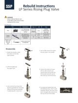
1. Mount the Inlet Swivel Assembly Plug in the Bench Vise and firmly attach the Regulator.
2. Remove the front half of the Gauge Guard [3] by removing the three Torx Head Screws
from the back side.
The Lenses can now be remove/replaced if desired, by simply snapping the old Lenses
out and the new Lenses in.
3. Remove the Knob by removing the Knob Decal, then removing the #10-32 Screw and
Washer found inside the Knob [8].
4. Remove the Outlet Connection [18] from the Body, then remove the Bonnet [2].
To keep the Body from spinning while removing the Bonnet, use Leverage Bar 1420-
0299 in the Outlet Port to obtain leverage to hold the Body, as shown in FIGURE 2.
Bench
Vise
Bonnet
FIGURE 2
Gauge Guard
Front Half
FIGURE 1
DISASSEMBLY:
Lens Snap Tabs
Leverage Bar
Inlet Swivel
Assembly Plug
Outlet Port

ESS42
- 7 -
SECTION 1
5. Remove the Adjusting Screw Assembly [9], Adjusting Spring [10], then remove the Backup
Plate, Diaphragm and Diaphragm O-Ring Seal [6].
Make sure you’ve got the Thrust Washer. If it’s not sitting on top of the Adjusting Screw
Assembly, it may still be up inside the Bonnet.
6. Remove all the Seat Assembly components (Nozzle w/O-Ring, Seat Assembly, Spring,
Gland and Friction Damper) [11], then remove the Seat Guide [12] from the Body.
7. Remove the Relief Valve or Pipe Plug [19], and any other Pipe Plugs [17] (if necessary)
from the Body.
8. Remove both HP and LP Gauges [20 and 21] by removing the two Torx Head Screws
holding each in place. Note that the Gauge may be “stuck” in the Body on its O-Ring Seal.
DO NOT pull up forcefully on the Gauge Face, as this can damage the Gauge! If a LIGHT
pull doesn’t pull the gauge out, lightly pry on the brass base underside of the Gauge with
a Flat Head Screwdriver, and “rock” it gently to get it to release from the O-Ring Seal and
come out.
Be careful not to touch any of the inner workings of the Gauge. Handle the Gauge by
holding onto the plastic face only.
Flat Head
Screwdriver
FIGURE 4
FIGURE 3
DISASSEMBLY:
Diaphragm
Backup Plate
Adjusting Screw
Assembly
Adjusting Spring
Thrust Washer
Only pry on the solid
brass base of the Gauge

ESS42
- 8 -
SECTION 1
9. Carefully remove the Gauge O-Rings, taking care not to scratch any sealing surfaces.
There is one O-Ring per Gauge. Typically they will remain in the body after Gauge removal,
but if not there, they may also still be on the Pressure Port of the Gauge itself.
10. It is not required to remove the back half of the Gauge Guard [4] for any repairs that may
be needed, but if removal is desired, simply remove the three Torx Head Screws holding it
in place.
11. Install Leverage Bar 1420-0299 into any ¼ NPT port in the Body (if not already there), and
use the bar to unscrew the Body off the Inlet Swivel [14].
Watch the Inlet Swivel while trying to turn the Body. If the Swivel is turning with the
Body, then you need to tighten the Inlet Nut tighter on the Inlet Swivel Assembly Plug.
12. If necessary, disassemble the Relief Valve as shown in DETAIL A.
m CAUTION! You should never reuse the Nozzle O-Ring, Seat Assembly, Friction
Damper, Inlet Filter or Diaphragm O-Ring Seal. Replace them with new parts each
time you assemble a Regulator.
CLEANING PARTS
It is recommended to clean all metal parts for oxygen service, regardless of Regulator Model
being repaired. There are several ways to clean components for oxygen service; the following
standards are recommended reading for more detailed information on methods and processes:
CGA G-4.1 “Cleaning Equipment for Oxygen Service”
ASTM G-93 “Standard Practice for Cleaning Methods and Cleanliness Levels for
Material and Equipment Used in Oxygen-Enriched Environments”
ASTM G-127 “Standard Guide for the Selection of Cleaning Agents for Oxygen
Systems”
Gauge
FIGURE 5
Regulator
Body
Gauge Guard
Back Half
DISASSEMBLY:
Pressure Ports
Pressure Port
Mounting Screws for
Gauge Guard Back Half

ESS42
- 9 -
SECTION 1
For metal parts,
VICTOR
suggests using CCI Envirospray Liquid, used per the manufacturer's
instructions, followed by a hot water rinse and thorough drying. Additional information can be
found at http://www.ccichemical.com.
DO NOT allow non-metal parts to come in contact with cleaning solvents. Cleaning solvents
can cause non-metal parts to swell and/or crack. To clean these parts, use a non-petroleum
based mild soap solution, followed by a thorough rinsing in water. Dry parts completely prior
to reassembling.
ASSEMBLY PROCEDURES
Refer to the exploded view for reference numbers [Shown in brackets]
m IMPORTANT NOTES ABOUT SEALING PIPE THREADS:
When using Teflon® tape where noted: Apply two to three layers around the
threads, leaving the first thread clean. Insure your Teflon® tape is oxygen-
compatible.
When using Loctite® #222 Threadlocker where noted: Apply two to three drops
to the second and third thread, leaving the first thread clean.
1. Install a new Filter [15] into the Inlet Swivel (or replace entire Inlet Swivel w/Filter installed
[14]), and apply Teflon® tape to the Inlet Swivel threads.
2. If not already in place, mount the Inlet Swivel Assembly Plug back in the Bench Vise. Firmly
attach the Inlet Swivel and Inlet Nut [13] onto the Inlet Swivel Assembly Plug. Install
Retaining Ring [16], if equipped.
3. Screw the Body onto the Inlet Swivel, screw the Leverage Bar 1420-0299 into the outlet
port of the Body (light hand tight), and then use the Leverage Bar to tighten the Body onto
the Inlet Connection. At this point, tighten enough so that the body cannot be turned by
hand without the assistance of the Leverage Bar. Final torque for the Inlet Connection will
occur in upcoming STEP 15.
Bench
Vise
Regulator
Body
FIGURE 6
ASSEMBLY:
Leverage Bar
Inlet Swivel
Assembly Plug

ESS42
- 10 -
SECTION 1
4. Preassemble the Relief Valve (if so equipped): Assemble (or reassemble) the Relief
Valve [19] as shown in DETAIL A. Use no lubricants or sealants. If your Regulator model
has a Pipe Plug instead of a Relief Valve, or if your Relief Valve is already assembled and
tested, you can skip to STEP 8.
5. To ensure proper Relief Valve performance, perform the following test procedures before
assembling the Relief Valve in the Regulator.
a. Attach the Relief Valve to a 450 PSIG source of oil-free air or dry nitrogen.
b. Slowly pressurize the Relief Valve, increasing to the recommended blow-off pressure
listed in TABLE 2 below. Note that
VICTOR Relief Valves are stamped with their nominal
set pressure, in case you’re unsure which Relief Valve you have.
Non-Vented Relief Valves:
If the Relief Valve vents before the minimum blow-off pressure is reached, then a
second Disc [27E] may be added.
If it still vents, then the Spring [27F] must be replaced.
Vented Relief Valves:
If the Vented Relief Valve fails to vent within the recommended blow-off pressure, reset
the Adjusting Screw [27J] as necessary and perform this step again. Make sure you
fully bleed off all pressure each time you test for blow-off pressure.
TABLE 2 – Relief Valve Blow-off Pressure
Relief Valve
Nominal Set Point
Recommended
Blow-off Pressure
60 PSIG 55 to 66 PSIG
100 PSIG 90 to 110 PSIG
200 PSIG 180 to 220 PSIG
300 PSIG 270 to 330 PSIG
400 PSIG 360 to 440 PSIG
6. When all testing is completed, bleed pressure off the Relief Valve. Install the Cap Nut [27K]
on the Vented Relief Valve.
7. Apply Teflon® tape to the Relief Valve [19] threads. Install the Relief Valve (or Pipe Plug)
into the Body and torque to 15 ft-lbs MIN.
8. Apply Teflon® tape to any other Pipe Plug [17] threads. Install Pipe Plugs into the Body
where appropriate, and torque to 15 ft-lbs MIN.
The Outlet Connection gets installed after STEP 18.
9. At this point, thoroughly blow out the Body assembly with pressurized oil-free air or dry
nitrogen to insure it is completely free of chips and debris.
10. If the back half of the Gauge Guard was removed, reinstall it now using three Torx head
screws. Torque Screws to 16 - 20 in-lbs.
ASSEMBLY:

ESS42
- 11 -
SECTION 1
11. Gauge Installation: The Edge 2.0 regulator uses new Gauge technology that utilizes an
O-Ring seal, thereby eliminating messy Teflon® tape and burr/chip generation from pipe
threads. While very easy to install, care must be taken to ensure a leak-free installation.
a. The Gauge O-Ring installs into the REGULATOR BODY, not onto the Gauge, and
must be carefully pushed down into the Body until it contacts the shoulder shown:
b. This location is critical for leak-free installation. Use the O-Ring Installation Tool 1420-
0344 to push the O-Ring down against the shoulder – it will move easy, and you will
feel a positive stop once in position. No lubrication is required on the O-Ring.
Gauge Pressure Port
Body
O-Ring
Installation
Tool
FIGURE 7
FIGURE 8
ASSEMBLY:
O-Ring must contact
this shoulder
O-Ring shown in correct
installed position

ESS42
- 12 -
SECTION 1
c. Next, install the Gauge itself by
simply pushing the Gauge onto the
O-Ring and Body. DO NOT push on
the plastic face of the Gauge.
Instead, use your hand grip on the
Gauge face as a guide only, and use
a Flat Head Screwdriver to push on
the exposed brass portion of the
Gauge as shown. It doesn’t matter
which gauge is installed first, but
typically it’s easier to install the HP
Gauge first, since it sits slightly under
the larger LP Gauge.
d. Once the Gauge is pushed in all the
way, and the metal face of the Gauge
has contacted the face of the Body,
the Gauges should naturally hold
themselves in position. Now, simply
install the two Torx Head Screws
included with the Gauges. Torque
Screws to 4.0 ± 0.4 in-lbs.
12. Install the Seat Guide [12] into the Body – it should slip in freely. Note its orientation when
installing – the cupped end with the hex on it should face up.
13. Preassemble the seat components [11]: Push the Friction Damper into the Gland, and
then slip the Valve Spring, Gland and Friction Damper onto the shaft of the Seat Assembly.
The Friction Damper should have enough tension to hold the Gland and the Valve
Spring in position on the shaft of the Seat Assembly. If there appears to be no tension
(if the parts just seem to want to fall off), then there may be a problem with your Friction
Damper, or the Friction Damper may not be firmly pushed up in place inside the Gland.
Flat Head
Screwdriver
FIGURE 9
FIGURE 10
FIGURE 11
ASSEMBLY:
Push in
these
areas only
to install
Gauges
Seat Guide
Friction Damper
installs up inside
Gland
Gland
Spring
Seat Assembly

ESS42
- 13 -
SECTION 1
14. Install the preassembled seat components into the Regulator Body – with the Friction
Damper and Gland fitting down into the cup shape of the Seat Guide.
15. Apply a light coat of CHRISTO-LUBE® #129 Lubricant to the Nozzle O-Ring, and install
the new O-Ring onto the Nozzle, taking care to guide it carefully over the Nozzle threads
to avoid nicks or tears. Install the Nozzle into the Regulator Body and torque to 15 - 20 ft-
lbs. Note that 15 - 20 ft-lbs is the same recommended torque for the Inlet Connection
Swivel, so as you torque down the Nozzle, you’re also finish-tightening the Inlet Swivel
to the correct torque value.
Watch the Inlet Swivel while you torque down the Nozzle. If the Swivel is turning with
the Body, then you need to tighten the Inlet Nut tighter on the Inlet Swivel Assembly
Plug. You want to be sure that the 15 - 20 ft-lbs torque is being applied to both the
Nozzle threads and the Inlet Swivel threads.
16. Apply a light coat of CHRISTO-LUBE® #129 Lubricant to the Diaphragm O-Ring Seal [6],
then install the O-Ring into the groove in the top of the Body.
17. Install the Diaphragm onto the Regulator Body, ensuring it is centered within the small lip
on the top of the Body. Then install the Backup Plate, Adjusting Spring [10], and Adjusting
Screw Assembly [9]. Don’t forget the Thrust Washer! It should be sitting on top of the
Adjusting Screw Assembly. Regulator function will be impaired without it.
FIGURE 12
FIGURE 13
ASSEMBLY:
O-Ring in groove
Thrust Washer
Diaphragm
Backup Plate
Adjusting Screw
Assembly
Adjusting Spring

ESS42
- 14 -
SECTION 1
18. Install the Bonnet [2] onto the Body. Take care while slipping the Bonnet down over the
internal components – the ribs inside the Bonnet must slide into the scallops of the Guide
Bushing. Torque the Bonnet to 45 - 50 ft-lbs.
Use the Leverage Bar 1420-0299 in the open Outlet Port to prevent the assembly from
rotating while torqueing the Bonnet.
19. Apply only Loctite® #222 threadlocker to the Outlet Connection [18] threads. Install the
Outlet Connection into the Body and torque to 15 ft-lbs MIN.
20. Apply a small amount of CHRISTO-LUBE® #129 to the top surface of the Bonnet (the
surface around the square of the Drive Screw), then slip the Knob [8] into position – the
square hole inside the knob mates to the square shaft of the Drive Screw.
21. Install the #10-32 Screw and Washer to hold the Knob on. Torque this Screw to 30 - 36 in-
lbs. Then apply the new Knob Decal.
22. Snap new Lenses into the front half of the Gauge Guard [3] (unless already installed), and
install the front half of the Gauge Guard onto the regulator using three Torx Head Screws
from the back side. Torque Screws to 16 - 20 in-lbs.
23. Apply new Gas I.D. and Compliance Decals [22] as needed to ensure the Regulator
maintains clear visual identification.
24. Disconnect the Regulator from the Inlet Swivel Assembly Plug. The Regulator is now ready
for testing.
TABLE 3 - Torque Specifications Summary
Seat Nozzle / Encapsulated Seat 15 - 20 ft-lbs.
Bonnet 45 - 50 ft-lbs.
Inlet Connection 15 - 20 ft-lbs.
Outlet, Relief Valve, Pipe Plugs 15 ft-lbs. MINIMUM
Gauge Screws
(M2.5 Screws Included w/Gauges)
4.0±0.4 in-lbs.
Gauge Guard Screws
(M3.5 Thread Forming Screws)
16 - 20 in-lbs.
Adjusting Mechanism Screws
(10-32 Thread Self Locking Screws)
30 - 36 in-lbs.
FIGURE 14
ASSEMBLY:
Gas I.D. Decal (Front)
Compliance Decal (Rear)

ESS42
- 15 -
SECTION 1
RECOMMENDED TOOLS AND SUPPLIES FOR TEST PROCEDURES
Test Gun (quick opening on/off valve) with #52 (.0635”) restricting orifice
Valved source of oil-free air or dry nitrogen
TEST PROCEDURES
m WARNING! m
For your safety, and the safety of others:
Always test with oil-free air or dry nitrogen only.
Always wear eye protection while testing a Regulator.
Always perform all of the following test procedures after reassembling a Regulator.
1. Set gas supply to the proper pressure shown in the following table:
TABLE 4 – Edge 2.0 Regulator Test Pressures
Gas Service Manifold Pressure for Testing
Acetylene & LP Gas 250±20 PSIG
CO
2
& N
2
O 1000±100 PSIG
Air, Argon, Hydrogen, Helium, Nitrogen, Oxygen 2000±100 PSIG
2. Attach the Regulator to the gas supply – start the Inlet Nut by hand (do not force), and
tighten securely with a wrench to create a seal.
3. Contamination purge prior to test:
a. Turn the Regulator Adjusting Knob clockwise two or three times until you feel slight
tension being applied to the Adjusting Spring.
b. Slowly open and close the Gas Supply Valve two or three times to remove
contamination that may cause malfunctions. Leave the Gas Supply Valve closed.
c. If no flow comes through the Regulator, determine the cause – refer to the
TROUBLESHOOTING CHART at the end of this section.
4. Turn the Adjusting Knob counterclockwise until it stops, and attach the Test Gun (with a
#52 restricting orifice) to the outlet of the Regulator.
5. Open the Gas Supply Valve and close the Test Gun.
a. Working pressure will appear on the High Pressure Gauge.
b. If the Low Pressure Gauge begins to show pressure building, turn the Gas Supply Valve
off and refer to the TROUBLESHOOTING CHART.
6. Use the values in the following table for all subsequent tests:
TABLE 5 – Edge 2.0 Regulator Test Values
Edge™ 2.0
Model
A
Pressure Set
for Leak Test
B
Pressure Set for
Creep/Drop Test
C
Drop
Allowance
D
Initial Shut-off
Allowance
ESS42-15-
15 PSIG 5 PSIG 3 PSIG 1 PSIG
ESS42-60-
60 PSIG 10 PSIG 3 PSIG 2 PSIG
ESS42-150-
150 PSIG 20 PSIG 4 PSIG 3 PSIG
TESTING:
/