Xpelair CF40TD User manual

Type
User manual
567-2077-01
Revision C
Guarantee
UK: This fan is guaranteed against defects for 3 years from the date of purchase.
• Xpelair reserve the right to repair or replace the fan.
• Keep your purchase receipt.
Any problems, contact the address below.
Outside UK: See International section below.
Technical Advice & Service
UK - Xpelair have a comprehensive range of services including:
• Free technical advice Help-Desk from Engineers on all aspects of ventilation.
• Free design service, quotations and site surveys.
Outside UK: See International section below.
Please ask for details on:
Tel +44 (0) 8709 000430
Fax +44 (0) 8709 000530
Also at the address below
Head Office – UK Sales Office and Spares
Applied Energy Products Ltd, Morley Way, Peterborough, PE2 9JJ, England
Tel: +44 (0) 1733 456789
Fax: +44 (0) 1733 310606
Sales/Spares Hotline: +44 (0) 8709 000420
Sales/Spares Faxline: +44 (0) 8709 000520
Web: http://www.xpelair.co.uk
International
Guarantee – Contact your local distributor or Xpelair direct
Technical advice and Service - Contact your local Xpelair distributor.
GB
F
D
NL
N
S
I
GR
a
Xpelair
Condensation Control Fans
CF40 Pull Cord
CF40TD Pull Cord/Timer
CF40RSTD Remote Switched/Timer
Centrifugal Ducted Fans
DX400 Remote Switched
DX400PC Pull Cord
DX400T Remote Switched/Timer
DX400RS Remote Switched
Installation and maintenance instructions
Retain for future reference
ES
Options Auxiliaires
Pour que l'installation soit plus
rapide et plus facile, il peut être
nécessaire d'utiliser les options
auxiliaires indiquées ci-dessous.
WD100 Gaine Murale
CFWG100 Grille Murale
XCT100 Collecteur de
Condensation
DGW/B Grille de porte de
renouvellement de
l’air
SP100 Plaque de
Centrage
XAA Adaptateur de
Brique d'Air
VC10 Capot d'Aération
WT10 Kit de Gaine de
Terminaison
XF/FM 6. Gaîne plate
(Plastique/Métal)
(Plastique 234 x 29
/ Métal 230 x 35)
VK10 Kit d'Aération
Murale
KHWG Grille Murale
(Noire)
FD100 Gaine Souple
WDC5 Clips à Vis Sans
Fin
XCMK Kit de Montage au
Plafond
XBP Volet de
Refoulement en
Ligne
EFT Kit d'Installation
Facile de
Terminaison
PDXGF Filtre de Graisse
Rechanges
On indique ci-dessous quelques-
unes des rechanges disponibles.
Voir la dernière page de ce
manuel pour les informations en
vue de passer commande :
41761SK Moteur (DX400)
41762SK Moteur (DX400PC)
41763SK Moteur (CF40)
41764SK Ensemble CCI
(Carte de Circuit
Imprimé) (DX400T)
41765SK
Ensemble CCI
(Carte de Circuit
Imprimé)
(DX400RS)
41766SK Ensemble CCI
(Carte de Circuit
Imprimé) (CF40)
41767SK Ensemble CCI
(Carte de Circuit
Imprimé) (CF40TD)
41768SK Ensemble CCI
(Carte de Circuit
Imprimé)
(CF40RSTD)
41774SK Couvercle Avant
avec Chicane
(DX400/CF40)
41771SK Encadrement
Moulé (Gamme
Complète)
41772SK Ensemble Cordon
de Tirage (Gamme
Complète)
Zusatzteile
Für eine schnellere und leichtere
Installation werden
möglicherweise einige der unten
aufgeführten Zusatzteile benötigt:
WD100 Wandkanal
CFWG100 Wandgitter
XCT100 Kondensatablauf
DGW/B Luftaustausch-
türgitter
SP100 Rohranschluss-
stutzenplatte
XAA Hohlziegeladapter
VC10 Lüftungskappe
WT10 Endkanal-
montagesatz
XF/FM Flachkanal (Metall
/ Plastik) (Plastik
234 x 29 / Metall
230 x 25)
VK10 Wandentlüftung-
smontagesatz
KHWG Wandgitter
(schwarz)
FD100 Biegsamer
Leitungskanal
WDC5 Schnecken-
gewinde-Schellen
XCMK Decken-
montagesatz
XBP Rückzugsklappe
EFT Schnellmontagesatz
Adapter für
Kanalende
PDXGF Fettfilter
Ersatzteile
Unten finden Sie einige der
verfügbaren Ersatzteile aufgelistet
Bestellangaben finden Sie auf der
Rückseite dieser Broschüre:
41761SK Motor (DX400)
41762SK Motor (DX400PC)
41763SK Motor (CF40)
41764SK Leiterplatte
(DX400T):
41765SK Leiterplatte
(DX400RS)
41766SK Leiterplatte (CF40)
41767SK Leiterplatte
(CF40TD)
41768SK Leiterplatte
(CF40RSTD)
41774SK Vorderabdeckung
mit Leitblech
(DX400/CF40)
41771SK Einfassungsteil
(Gesamtes
Sortiment)
41772SK Zugschnur
(Gesamtes
Sortiment)
Afwerkingsopties
Om de montage sneller en
gemakkelijker te laten verlopen,
heeft u eventueel volgende
afwerkingsmiddelen nodig.
WD100 Muurdoorvoer
CFWG100 Muurrooster
XCT100 Condensaatvanger
DGW/B Deurrooster
luchtverversing
SP100 Luchtinlaatplaat
XAA Gatensteenadapter
VC10 Luchtopeningskap
WT10 Afsluitkanaalkit
XF/FM Plat kanaal
(plastic / metaal)
(plastic 234 x 29 /
metaal 230 x 25)
VK10 Muuropeningskit
KHWG Muurrooster
(zwart)
FD100 Flexibel kanaal
WDC5 Wormklemmen
XCMK Plafondmontagekit
XBP Tochtsluiter
EFT Easy Fit
afsluitadapter
PDXGF Vetfilter
Wisselstukken
Hierna vindt u enkele leverbare
wisselstukken. De
bestelgegevens vindt u op de
achterflap van deze brochure:
41761SK Motor (DX400)
41762SK Motor (DX400PC)
41763SK Motor (CF40)
41764SK Print (DX400T)
41765SK Print (DX400RS)
41766SK Print (CF40)
41767SK Print (CF40TD)
41768SK Print (CF40RSTD)
41774SK Schermplaat met
schot
(DX400/CF40)
41771SK Montageplaat-
sierstrip (volledig
gamma)
41772SK Trekkoordsysteem
(volledig gamma)
Ancillary Options
For speed and ease of
Installation, your installation may
require some of the Ancillaries
listed below:
WD100 Wall Duct
CFWG100 Wall Grille
XCT100 Condensation Trap
DGW/B Air Replacement
Door Grille
SP100 Spigot Plate
XAA Air Brick Adaptor
VC10 Vent Cowl
WT10 Termination Ducting
Kit
XF/FM Flat Ducting
(Plastic / Metal)
(Plastic 234x29
/ Metal 230x25)
VK10 Wall Vent Kit
KHWG Wall Grille (Black)
FD100 Flexible Ducting
WDC5 Worm Drive Clips
XCMK Ceiling Mounting Kit
XBP In-Line Back
Draught Shutter
EFT Easy Fit
Termination Kit
Adaptor
PDXGF Grease Filter
Spares
Listed below are some of the
spares available. See back-page
of this booklet for ordering details:
41761SK Motor (DX400)
41762SK Motor (DX400PC)
41763SK Motor (CF40)
41764SK PCB Assy
(DX400T)
41765SK PCB Assy
(DX400RS)
41766SK PCB Assy (CF40)
41767SK PCB Assy
(CF40TD)
41768SK PCB Assy
(CF40RSTD)
41774SK Front Cover c/w
Baffle
(DX400/CF40)
41771SK Surround Moulding
(Entire Range)
41772SK Pull-Cord Assembly
(Entire Range)
GB
F D NL
G
F
Cableado de las conexiones eléctricas
1. Aísle el suministro eléctrico y retire todos los
fusibles. La caja de terminales es apta para cables
de hasta 2.5mm
2
.
2. Utilice un conmutador de aislamiento de dos polos con
una separación mínima de contacto de 3 mm en
ambos polos.
3. Utilice un cable de 3 almas o 4 almas de la
clasificación correcta, dependiendo de la aplicación.
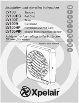
4. Cablee el ventilador como se muestra en la Fig.
F y
utilice la abrazadera para cables que se proporciona
a fin de asegurar el cable. Compruebe el modelo de
ventilador con el diagrama.
DX400: “LH” = Vivo (Alta
velocidad) / “LL” = Vivo (Baja velocidad).
5. Vuelva a colocar la tapa de la caja de terminales
5 y
apriete los tornillos de sujeción.
6. Consulte el apartado
“Ajustes del usuario” si desea
utilizar otros ajustes que no sean los ajustados en
fábrica.
7. Vuelva a colocar la cubierta frontal
2 (Fig. C).
8. Conecte el cable del conmutador de aislamiento al
cableado del suministro eléctrico y vuelva a
comprobar la instalación.
9. Antes de volver a conectar la electricidad, instale los
fusibles.
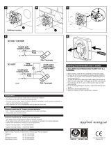
10. Para circuitos de cableado fijo, el fusible de seguridad
para el aparato no debe superar 5A.
Ajustes del usuario
Antes de llevar a cabo cualquier ajuste, aísle el
ventilador del suministro eléctrico de la red,
compruebe las especificaciones que se ofrecen
seguidamente, a fin de ver qué características son
aplicables al modelo de ventilador.
1. Retire la cubierta frontal y vuélvala a colocar después
del ajuste .
C)
DX400 / DX400PC / DX400RS
Estos modelos de ventiladores no pueden ser ajustados
por el usuario.
DX400T
1. 1. El periodo de rebase del temporizador puede
ajustarse entre aproximadamente 30 segundos y 20
minutos. Utilice un destornillador de electricista y gire
el tornillo “T” (Fig.
D), hacia la derecha para
incrementar el tiempo o hacia la izquierda para
reducirlo. (El ajuste de fábrica es de
aproximadamente 10 minutos).
CF40
1. El ajuste de humedad puede ajustarse entre
aproximadamente 50% y 90% de humedad relativa.
Utilice un destornillador de electricista u gire el tornillo
“RH” (Fig.
D) hacia la derecha para incrementar el
ajuste de humedad relativa y hacia la izquierda para
reducirla. (Nota: el ventilador es más sensible a 50%
de HR que a 90%).
CF40TD / CF40RSTD
1. El periodo de rebase del temporizador puede
ajustarse entre aproximadamente 30 segundos y 20
minutos. Utilice un destornillador de electricista y gire
el tornillo “T” (Fig.
D), hacia la derecha para
incrementar el tiempo o hacia la izquierda para
reducirlo. (El ajuste de fábrica es de
aproximadamente 10 minutos).
2. El ajuste de humedad puede ajustarse entre
aproximadamente 50% y 90% de humedad relativa.
Utilice un destornillador de electricista u gire el tornillo
“RH” (Fig.
D) hacia la derecha para incrementar el
ajuste de humedad relativa y hacia la izquierda para
reducirla. (Nota: el ventilador es más sensible a 50%
de HR que a 90%).
Uso del ventilador
DX400
Ponga en funcionamiento el ventilador utilizando el
interruptor de encendido / apagado externo. Repita el
procedimiento para apagarlo. La velocidad del ventilador
está preajustada por el instalador, bien a velocidad rápida
o lenta. (Si se ha instalado un inversor de corriente
entonces el usuario puede cambiar la velocidad de rápida
a lenta.)
DX400PC
Secuencia de funcionamiento del cordón:
Ventilador apagado (luz apagada)
Tire del cordón una vez, el ventilador se pone en
funcionamiento en velocidad rápida (“la luz II” está
encendida – alta intensidad)
Tire del cordón otra vez, el ventilador se pone en
funcionamiento en velocidad lenta (“la luz II” está
encendida – baja intensidad)
Tire del cordón otra vez, el ventilador se apaga (luz
apagada)
El instalador puede ajustar un interruptor interno a fin de
ofrecer extracción continua de fondo cuando está
“apagado”.
DX400T
Accione el ventilador utilizando el interruptor de encendido
/ apagado.
Cuando se encienda el interruptor, el ventilador funcionará
a velocidad rápida.
Cuando se apague el interruptor, el ventilador continúa
funcionando a velocidad lenta durante el periodo de
rebase del temporizador ajustable (“la luz I” está
encendida e indica que el ventilador está funcionando en
modo manual)
El instalador puede ajustar un interruptor interno a fin de
ofrecer extracción continua de fondo cuando está
“apagado”.
Función de demora de puesta en marcha encendida o
apagada.
Esta función la ajusta el instalador a fin de ofrecer una
demora de puesta en marcha de 2 minutos cuando se
enciende el ventilador utilizando el interruptor de
encendido / apagado externo.
DX400RS
Accione el ventilador utilizando el interruptor de encendido
/ apagado.
Seleccione velocidad rápida o lenta utilizando el
interruptor remoto. El instalador puede ajustar un
interruptor interno a fin de ofrecer extracción continua de
fondo cuando está “apagado”.
La “luz I” superior está encendida a alta densidad cuando
el ventilador funciona a velocidad rápida, y a intensidad
baja cuando el ventilador funciona a velocidad lenta. La
luz se apaga cuando el ventilador está apagado o
funciona a extracción lenta.
CF40 / CF40TD
Funcionamiento conmutado
El ventilador puede cablearse con un interruptor de
encendido / apagado separado. El ventilador funciona a la
velocidad de condensación cuando se enciende. La “luz I”
superior está encendida cuando se enciende el interruptor
de encendido / apagado separado. Cuando está apagado,
el ventilador continuará funcionando si el nivel de
humedad es superior al establecido por el tornillo de
ajuste “RH”. CF40TD solamente: Cuando se apaga, el
ventilador continúa funcionando durante el periodo de
rebase del temporizador ajustable.
Funcionamiento de la condensación
El ventilador se pine en funcionamiento a la velocidad de
control de condensación cuando la humedad relativa
supera el nivel establecido y se apaga cuando la
humedad relativa baja.
Funcionamiento de refuerzo
Secuencia del cordón:
Funcionamiento de condensación automático (Ambas
luces apagadas)
Tire del cordón una vez, el ventilador se pone en
funcionamiento en velocidad rápida (“luz II” inferior está
encendida – alta intensidad).
Tire del cordón otra vez, el ventilador se pone en
funcionamiento en la velocidad de condensación manual
(“luz II” inferior está encendida – baja intensidad)
Tire del cordón otra vez, el ventilador funciona a velocidad
de condensación automática (ambas luces apagadas)
Función lenta encendida o apagada
Esta función la ajusta el instalador a fin de ofrecer
extracción de fondo continua, cuando el nivel de humedad
es inferior al establecido por el tornillo de ajuste “RH” y el
ventilador está en el modo de condensación automático.
CF40TD solamente
Función de demora de puesta en marcha encendida o
apagada
Esta función la ajusta el instalador a fin de ofrecer una
demora de puesta en marcha de 2 minutos cuando el
ventilador se enciende utilizando un interruptor de
encendido / apagado separado.
CF40RSTD
Funcionamiento de la condensación
El ventilador funciona a la velocidad de control de la
condensación, cuando la humedad relativa supera el nivel
establecido, y se apaga cuando baja la humedad.
Funcionamiento de refuerzo
Accione el ventilador utilizando el interruptor de encendido
/ apagado. Seleccione velocidad rápida o lenta utilizando
el interruptor remoto. Cuando está apagado, el ventilador
continúa funcionando durante el periodo de rebase
ajustable. El instalador puede ajustar un interruptor interno
a fin de que el ventilador continúe ofreciendo extracción
de fondo continua cuando esté “Apagado”. La “luz I”
superior está encendida a intensidad alta cuando el
ventilador está funcionando a velocidad rápida, y a
intensidad baja cuando el ventilador está funcionando a
velocidad lenta. La luz está apagada cuando el ventilador
está Apagado o funcionando en el modo de extracción
lenta.
Limpieza
1. Antes de limpiar el ventilador, aísle el suministro
eléctrico de la red.
2. Limpie únicamente la superficie exterior del ventilador,
utilizando un paño húmedo sin pelusas.
3. No utilice detergentes fuertes, disolventes ni
limpiadores químicos.
4. Deje que el ventilador se seque completamente antes
de volver a usarlo.
5. Aparte de la limpieza, el ventilador no precisa ningún
otro mantenimiento.
Clave
Véase el diagrama E
1. Placa deflectora
2. Cubierta frontal
3. Impulsor
4. Tornillos de sujeción
5. Tapa de terminales
6. Caja del ventilador
7. Espiga circular
8. Tornillos de abrazadera y tirafondos – 3 x
9. Abrazaderas del cuerpo del ventilador – 3 x
10. Perímetro
11. Tornillos de techo 25 mm de largo 4 x (Diagrama
B)
12. Cinta de espuma
PARA EL BENEFICIO DEL USUARIO DEJE ESTE
FOLLETO CON EL VENTILADOR.
For speed and ease of Installation, your
installation may require some of the Ancillaries
indicated in “Ancillary Options”.
If installing on a wall (surface mounting)
1. Mark on the wall the centre of the duct hole A.
2. Use this centre to cut an opening through the wall
117mm diameter, with a slight fall to the exterior.
3. Fit the wall tube, not supplied, and mortar into
place.
If installing in a wall (flush mounting)
1. Mark on the wall the centre of the duct hole A,
and drill a pilot hole through both walls.
2. Use the centre to mark a rectangular hole for the
inner wall using the dimensions A.
3. Cut the rectangular hole through the inner wall.
4. Go outside and cut a 117mm diameter hole in the
outer wall using the small hole as the centre.
5. Measure the wall thickness.
Cut the wall tube (WD100), not supplied, so that it
is 85mm less than the wall thickness.
If installing on a ceiling (surface mounting)
This method requires a space above the ceiling, such
as a loft or attic, to provide access for 100mm internal
diameter ducting, or a minimum 70mm void using flat
ducting.
1. Mark on the ceiling the centre of the duct hole A,
avoiding ceiling joists and buried cables etc..
2. Cut a 117mm diameter hole using the marked
centre.
If installing in a ceiling (flush mounting)
For 100mm diameter ducting:
This method requires a space above the ceiling, such
as a loft or attic, to provide access for 100mm internal
diameter ducting.
1. Mark a rectangular hole using the dimensions B.
2. Cut the hole, avoiding ceiling joists and buried
cables etc.
For flat ducting:
This fan can be installed within a 140mm void with
the circular spigot
7.
Preparing the fan for installation
1. Remove the front cover 2 (Fig.C)
2. Fit the foam tape !™ supplied around the circular
spigot
7 (Fig.E).
3. Remove the electrical cover 5 (Fig.E).
Setting the condensation speed
CF40 / CF40TD / CF40RSTD Only (Fig.D)
4. The correct condensation control speed should be
selected to suit the room size in which the fan is to
be installed. Slide the switch X to the required
position. Please note that the fan is factory set to
“Position 2”.
5. Switch Position Size / Room Volume (m
3
)
1 Large (54 and above)
2 Medium (30 – 54)
3Small (less than 30)
Setting the trickle speed
All models except DX400 (Fig.D)
6. The fan can be set so that it provides constant
trickle extraction. Slide the switch Y to the
required position. Please note that the fan is factory
set to “Position 0”.
Switch Position Setting
0Trickle extraction OFF
ITrickle extraction ON
Setting the time delay start
DX400T / CF40TD Only (Fig. D)
7. The fan can be set so that there is a 2-minute
delayed start to its operation when used with an
external on/off switch. Slide the switch Z to the
required position. Please note that the fan is factory
set to “Position 0”.
8. Switch Position Setting
0Time delay start OFF
ITime delay start ON
Mounting the fan on a wall or ceiling (surface
mounting)
1. Place the ducting into the hole and align to the
required position. If wall mounting, ensure that the
ducting slopes down and away from the fan
2. Mark the positions of the three fixing holes A in
Fan box 6 (Fig.E).
3. If wall mounting, drill three holes 5.5mm diameter
for wall plugs (supplied). If ceiling mounting B,
use appropriate fasteners (not supplied).
4. Cut out the cable inlet hole, if required, in the
surround
0 and slit the cable grommet. Slide the
surround 0 over the fan box 6.
5. Pass the electrical cables into the fan box 6
through the rear cable inlet hole and surround,
and re-fit the cable grommet. Ensure that cable
grommet is in place and a tight fit.
6. Offer the fan box 6 up to the wall or ceiling.
Ensure the circular spigot 7 enters the ducting.
7. Fix the fan box 6 to the wall using screws 8 or to
the ceiling using appropriate fasteners (not
supplied).
If mounting in a wall (flush mounting)
The surround 0 is not required. Fit the ducting to the
circular spigot 7.
If the hole size is as recommended:
1. Assemble the three fan body clamps 9 to the fan
box 6 using screws 8.
2. Slit the cable grommet. Pass the electrical cables
into the fan box 6 through the cable inlet hole and
cable grommet.
Ensure cable grommet is in place and a tight
fit.
3. Offer the fan box 6 up to the wall. Ensure the
circular spigot 7 enters the ducting.
4. Tighten up the three screws 8 until the fan is
clamped to the inner wall. The fan body clamps 9
will rotate to an automatic stop position. DO NOT
OVERTIGHTEN.
If the hole size is larger than recommended i.e.:
larger than the flange on the fan box 6 (Mostly
relating to “retro-fit” installations):
1. The fan body clamps ARE NOT suitable.
Construct a wooden frame of INTERNAL
dimensions 232 x 280mm. Depth should be at
least 50mm. Fit the wooden frame into the internal
wall and make good the hole.
2. Offer the fan box 6 up to the wall. Ensure the
circular spigot 7 enters the ducting.
3. Screw the fan box 6 to the wooden frame using
the slots in the flange (screws not supplied).
If mounting in a ceiling (flush mounting)
1. The surround 0 is not required.
2. Insert the fan box 6 into the hole and mark four
positions using the slots in the flange B.
3. Remove the fan box 6 from ceiling and fit the four
ceiling clips (supplied) over the edge of the hole,
so that the clips align with the marks on the ceiling
B.
4. Drill 4 pilot holes into the ceiling through the hole
of each clip, ensuring not to damage the clip, and
fit the clips ensuring correct alignment.
5. Fit the ducting to the circular spigot 7.
6. Offer the fan box
6 up to the ceiling.
7. Slit the cable grommet. Pass the electrical cable
into the fan box 6 through the front cable inlet
hole.
Ensure cable grommet is in place and a tight
fit.
8. Using the screws (Fig.B), fix the fan box
flange to the ceiling clips.
Terminating the ducting
Fit the outer grille to the outer wall. For ceiling
mounting, use appropriate ancillaries (not supplied).
1. READ ALL THESE INSTRUCTIONS & WARNINGS FULLY BEFORE COMMENCING INSTALLATION.
2. INSTALLATIONS AND WIRING MUST CONFORM TO CURRENT IEE REGULATIONS (UK), LOCAL OR APPROPRIATE
REGULATIONS (OTHER COUNTRIES). IT IS THE INSTALLER’S RESPONSIBILITY TO ENSURE THAT THE APPROPRIATE
BUILDING CODES OF PRACTICE ARE ADHERED TO.
3. A QUALIFIED ELECTRICIAN MUST SUPERVISE ALL INSTALLATIONS.
4. THESE APPLIANCES ARE INTENDED FOR CONNECTION TO FIXED WIRING.
5. CHECK THAT THE ELECTRICAL RATING SHOWN ON THE FAN MATCHES THE MAINS SUPPLY.
6. W
ARNING: THESE APPLIANCES MUST BE EARTHED.
7. SITE AWAY FROM DIRECT SOURCES OF HEAT (I.E.: GAS COOKERS OR EYE-LEVEL GRILLS) AND NOT WHERE
AMBIENT TEMPERATURES ARE LIKELY TO EXCEED 50
O
C.
8. WHEN THE FAN IS INSTALLED IN A ROOM CONTAINING A FUEL BURNING APPLIANCE, THE INSTALLER MUST ENSURE
THAT AIR REPLACEMENT IS ADEQUATE FOR BOTH THE FAN AND THE FUEL BURNING APPLIANCE.
9. ENSURE THAT ALL RELEVANT SAFETY PRECAUTIONS (CORRECT EYE PROTECTION AND PROTECTIVE CLOTHING
ETC) ARE TAKEN WHEN INSTALLING, OPERATING AND MAINTAINING THIS FAN.
10. GENERAL GUIDANCE FOR SITING THE FAN SEE “FIG. G”. ALWAYS SITE FAN AS HIGH AS POSSIBLE
11. IF ANY SECTION OF THE DUCTWORK IS POSITIONED HIGHER THAN THE FAN A CONDENSATION TRAP (XCT100) MUST
BE FITTED AS CLOSE AS POSSIBLE TO THE FAN.
12. THE APPLIANCE IS NOT INTENDED FOR USE BY YOUNG CHILDREN OR INFIRM PERSONS. YOUNG CHILDREN
SHOULD BE SUPERVISED TO ENSURE THEY DO NOT PLAY WITH THE APPLIANCE.
GB
IMPORTANT
A fin de agilizar y facilitar la instalación, es posible
que la instalación precise algunos de los equipos
auxiliares indicados en el apartado “Opciones
auxiliares.”
Si se instala en una pared (montaje en superficie)
1. Marque en la pared el centro del orificio del conducto A.
2. Utilice este centro para cortar una abertura de 117 mm
de diámetro a través de la pared, con una ligera caída
hacia el exterior.
3. Instale el tubo de pared, no suministrado, y fíjelo en
posición con argamasa.
Si se instala en una pared (montaje a paño)
1. Marque en la pared el centro del orificio del conducto
A, y taladre un agujero piloto a través de ambas
paredes.
2. Utilice el centro para marcar un orificio rectangular
para la pared interior, utilizando las dimensiones A.
3. Corte el orificio rectangular a través de la pared interior.
4. Vaya fuera y corte un orificio de 117 mm de diámetro
en la pared exterior, utilizando el orificio pequeño
como centro.
5. Mida el espesor de la pared.
Corte el tubo de pared (WD100), no se suministra, de
forma que tenga 85 mm menos que el espesor de la
pared.
Si se instala en el techo (montaje en superficie)
Este método precisa disponer de espacio encima del techo,
por ejemplo un ático o un trastero, que proporcione acceso
para el conducto interno de 100 mm, o en un vacío de
70mm como mínimo cuando se usan conductos planos.
1. Marque en el techo el centro del orificio del conducto
A, evitando las vigas del techo, los cables enterrados,
etc.
2. Corte un orificio de 117 mm utilizando el centro
marcado.
Si se instala en el techo (montaje a paño)
Para conductos de 100 mm:
Este método precisa disponer de espacio encima del techo,
por ejemplo un ático o un trastero, que proporcione acceso
para el conducto interno de 100 mm.
1. Marque un orificio rectangular utilizando las
dimensiones B.
2. Corte el orificio, evitando las vigas del techo, cables
enterrados, etc.
Para conductos planos:
Este ventilador puede instalase dentro de un vacío de
140mm con la espiga circular 7.
Preparar el ventilador para la instalación
1. Retire la cubierta frontal
22
(Fig.C)
2. Coloque la cinta de espuma !™ que se suministra
alrededor de la espiga circular 7 (Fig. E)
3. Retire la cubierta eléctrica 5 (Fig. E)
Ajuste de la velocidad de condensación
CF40 / CF40TD / CF40RSTD solamente (Fig. D)
4. Debe seleccionarse la velocidad de control de la
condensación adecuada para las dimensiones de la
habitación en la que va a instalarse el ventilador.
Coloque el interruptor X en la posición deseada. Tenga
en cuenta que por defecto el ventilador está ajustado en
la “Posición 2”.
5. Posición del interruptor Dimensiones / volumen de la
habitación (m
3
)
1 Grande (54 y más grande)
2Mediana (30-54)
3 Pequeña (menos de 30)
Ajuste de la velocidad lenta
Todos los modelos excepto DX400 (Fig.D)
6. El ventilador puede ajustarse de forma que ofrezca una
extracción lenta constante. Coloque el interruptor Y en
la posición deseada. Tenga en cuenta que por defecto
el ventilador está ajustado en la “Posición 0”.
Posición del interruptor Ajuste
0Extracción lenta DESCONECTADA
I Extracción lenta CONECTADA
Ajuste de puesta en marcha con demora de tiempo
DX400T / CF40TD solamente (Fig. D)
7. El ventilador puede ajustarse con una demora de 2
minutos para la puesta en marcha cuando se utilice con
un interruptor de encendido / apagado externo. Coloque
el interruptor Z en la posición deseada. Tenga en
cuenta que por defecto el ventilador está ajustado en la
“Posición 0”.
8. Posición del interruptor Ajuste
0 Demora DESCONECTADA
I Demora CONECTADA
Montaje del ventilador sobre una pared o techo
(montaje en superficie)
1. Coloque el conducto en el orificio y alinéelo en la
posición deseada. Si se monta en la pared, asegúrese
que el conducto tenga una caída lejos del ventilador.
2. Marque las posiciones de los tres orificios de sujeción
A en la caja del ventilador
66
(Fig.E).
3. Si se monta en la pared, taladre tres orificios de 5,5
mm de diámetro para los tirafondos (suministrados). Si
se monta en el techo B, utilice las sujeciones
adecuados (no suministradas).
4. Corte el orificio de entrada del cable, si se precisa, en
el perímetro 0 y haga un corte longitudinal en el ojal
del cable. Deslice el perímetro 0 sobre la caja del
ventilador 6.
5. Introduzca los cables eléctricos en la caja del
ventilador 6 a través del orificio de entrada de cables
y perímetro posteriores, y vuelva a colocar el ojal del
cable. Asegúrese que el ojal del cable se
encuentre en posición y apriételo.
6. Coloque la caja del ventilador 6 en la pared o techo.
Asegúrese que la espiga circular 7 se introduzca en
el conducto.
7. Ajuste la caja del ventilador 6 en la pared, utilizando
los tornillos 8 o en el techo utilizando las sujeciones
adecuadas (no suministradas).
Si se monta en la pared (montaje a paño)
No se necesita el perímetro 0. Coloque el conducto en la
espiga circular 7.
Si el tamaño del orificio es el recomendado:
1. Monte las tres abrazaderas del cuerpo del ventilador
9 en la caja del ventilador 6 utilizando los tornillos
88
.
2. Haga un corte longitudinal en el ojal del cable. Introduzca
los cables eléctricos en la caja del ventilador 6 a través
del orificio de entrada de cables y del ojal del cable
Asegúrese que el ojal del cable se encuentre en
posición y apriételo.
3. Coloque la caja del ventilador 6 en la pared o techo.
Asegúrese que la espiga circular 7 se introduzca en
el conducto.
4. Apriete los tres tornillos 8 hasta que el ventilador
quede sujeto a la pared interior. Las abrazaderas del
cuerpo del ventilador 9 girarán a una posición de tope
automática. NO APRETAR DEMASIADO.
Si el tamaño del orificio es mayor que el recomendado,
es decir, más grande que la brida en la caja del
ventilador 6 (Principalmente se refiere a instalaciones
“retroajustadas”):
1. Las abrazaderas del cuerpo del ventilador NO SON
adecuadas. Construya un bastidor de madera con
dimensiones INTERIORES de 232 x 280 mm. La
profundidad debe ser de al menos 50 mm. Ajuste el
bastidor de madera en la pared interior y cubra el orificio.
2. Coloque la caja del ventilador 6 en la pared.
Asegúrese que la espiga circular 7 se introduzca en
el conducto.
3. Atornille la caja del ventilador 6 al bastidor de
madera, utilizando las ranuras en la brida (no se
suministran los tornillos).
Si se monta en el techo (montaje a paño)
1. No se necesita el perímetro 0.
2. Introduzca la caja del ventilador 6 en el orificio y
marque cuatro posiciones utilizando las ranuras en la
brida B.
3. Retire la caja del ventilador 6 del techo y ajuste las
cuatro pinzas para el techo (que se suministran) sobre
el borde del orificio de forma que las pinzas se alineen
con las marcas en el techo B.
4. Taladre cuatro orificios de guía en el techo, a través del
orificio de cada pinza, asegurándose que no se dañen
las pinzas, y ajuste las pinzas asegurándose que
están alineadas correctamente.
5. Ajuste el conducto en la espiga circular 7.
6. Coloque la caja del ventilador 6 en el techo.
7. Haga un corte longitudinal en el ojal del cable.
Introduzca el cable eléctrico en la caja del ventilador
6 a través del orificio de entrada de cables frontal.
Asegúrese que el ojal del cable se encuentre en
posición y apriételo.
8. Utilizando los tornillos (Fig. B), ajuste la brida de la
caja del ventilador en las pinzas de techo.ndo los brida
Terminación del conducto
Instale la rejilla exterior en la pared exterior. Para
montajes en el techo, utilice los equipos auxiliares
adecuados (no suministrados).
1. LEA TODAS LAS INSTRUCCIONES Y AVISOS DETALLADAMENTE ANTES DE COMENZAR LA INSTALACIÓN.
2. LAS INSTALACIONES Y EL CABLEADO DEBEN CUMPLIR LAS NORMATIVAS LOCALES ACTUALES (RU) O LAS NORMATIVAS APROPIADAS
(OTROS PAÍSES.) ES LA RESPONSABILIDAD DEL INSTALADOR ASEGURARSE QUE SE CUMPLEN LOS CÓDIGOS DE PRÁCTICA SOBRE
CONSTRUCCIÓN.
3. UN ELECTRICISTA COMPETENTE DEBE SUPERVISAR TODAS LAS INSTALACIONES.
4. ESTOS EQUIPOS DEBEN CONECTARSE A UNA RED DE CABLEADO FIJA.
5. VERIFIQUE QUE LA CLASIFICACIÓN ELÉCTRICAQUE SE MUESTRA EN EL VENTILADOR SE CORRESPONDA CON EL SUMINISTRO DE LA RED.
6. A
VISO: ESTOS EQUIPOS DEBEN ESTAR CONECTADOS A TIERRA.
7. LEJOS DE FUENTES DIRECTAS DE CALOR (P. EJ. COCINAS DE GAS O PARRILLAS) Y NUNCA DONDE EXISTA LA POSIBILIDAD DE QUE
LA TEMPERATURA AMBIENTE SEA SUPERIOR A LOS 50°C.
8. CUANDO EL VENTILADOR SE INSTALE EN UNA HABITACIÓN QUE CONTENGA UN APARATO QUE QUEME COMBUSTIBLE, EL
INSTALADOR DEBE ASEGURARSE QUE LA CIRCULACIÓN DE AIRE FRESCO SEA ADECUADA TANTO PARA EL VENTILADOR COMO PARA
EL APARATO QUE QUEME COMBUSTIBLE.
9. ASEGÚRESE QUE SE OBSERVAN TODAS LAS PRECAUCIONES DE SEGURIDAD RELEVANTES (PROTECCIÓN OCULAR Y ROPA DE
PROTECCIÓN CORRECTAS) CUANDO SE INSTALE, SE PONGA EN FUNCIONAMIENTO Y SE MANTENGA ESTE VENTILADOR.
10. LA FIGURA G OFRECE ORIENTACIÓN GENERAL PARA COLOCAR EL VENTILADOR. COLOQUE SIEMPRE EL VENTILADOR LO MÁS ALTO
POSIBLE.
11.SI CUALQUIERA DE LAS SECCIONES DEL CONDUCTO ESTUVIERA COLOCADA EN UNA POSICIÓN MÁS ALTA QUE EL VENTILADOR DEBE
INSTALARSE UNA TRAMPA DE CONDENSACIÓN LO MÁS CERCA POSIBLE DEL VENTILADOR.
ES
IMPORTANTE
Wire the electrical connections
1. Isolate the electricity supply and remove all
fuses.
The terminal block will accept cable up to
2.5mm
2
.
2. Use a double-pole isolating switch with a minimum
contact gap of 3mm in both poles.
3. Use suitably rated 3-core or 4-core cable
dependant on application.
4. Wire the fan as shown in
F and use the cable
clamp provided to secure the cable. Check fan
model to diagram.
DX400: “LH” = Live (High
Speed) / “LL” = Live (Low Speed)
5. Replace the terminal cover
5 and fasten the
retaining screws.
6. See section on “
User adjustments” if you wish to
use settings other than those that have been
factory set.
7. Refit the front cover
2 (Fig.C).
8. Connect the cable from the isolating switch to
electrical supply wiring, and re-check installation.
9. Refit fuses before turning on electricity supply.
10. For fixed wiring circuits, the protective fuse for the
appliance must not exceed 5A.
User adjustments
Before making any adjustments, isolate the fan
completely from the mains supply, check
specification below to see which features apply to
your fan.
1. Remove the front cover and replace after
adjustment (Fig.
C)
DX400 / DX400PC / DX400RS
There are no user adjustments for these fans.
DX400T
1. The timer over-run period can be adjusted
between approximately 30 seconds and 20
minutes. Use an electrician’s screwdriver and turn
screw “T” (Fig.
D), clockwise to increase time,
anti-clockwise to decrease. (Factory preset to
approximately 10 minutes)
CF40
1. The humidity setting is adjustable between
approximately 50% and 90% relative humidity.
Use an electrician’s screwdriver, and turn screw
“RH” (Fig.
D), clockwise to increase the relative
humidity setting and anti-clockwise to decrease.
(Note: the fan is more sensitive at 50% RH than
at 90%).
CF40TD / CF40RSTD
1. The timer over-run period can be adjusted
between approximately 30 seconds and 20
minutes. Use an electrician’s screwdriver and turn
screw “T” (Fig.
D), clockwise to increase time,
anti-clockwise to decrease.
2. The humidity setting is adjustable between
approximately 50% and 90% relative humidity.
Use an electrician’s screwdriver, and turn screw
“RH” (Fig.
D), clockwise to increase the relative
humidity setting and anti-clockwise to decrease.
(Note: the fan is more sensitive at 50% RH than
at 90%).
Using the fan
DX400
Operate the fan using the external on/off switch.
Repeat to switch off. The fan speed is pre-set by the
installer to either high or low speed. (If a change
over switch has been installed then the user can
switch between high speed and low speed.)
DX400PC
Pull Cord operation sequence:
Fan off (light off)
Pull cord once, fan operates on high speed (“light II
is lit - high intensity)
Pull cord again, fan operates on low speed (“light II
is lit - low intensity)
Pull cord again, fan off (light off)
An internal switch can be installer set to provide
continuous background extraction in the ‘Off’ state.
DX400T
Operate the fan using the on/off switch.
When the switch is turned on, the fan will operate at
High Speed.
When the switch is turned off, the fan continues to
operate at low speed for the adjustable timer over-run
period (“light I” is lit indicating fan is operating in
manual mode)
An internal switch can be installer set to provide
continuous background extraction in the ‘Off’ state.
Time delay start feature on or off.
This is set by the installer to provide a 2-minute time
delay start when the fan is switched on using the
external on/off switch.
DX400RS
Operate the fan using the on/off switch.
Select high or low speed using the remote switch.
An internal switch can be installer set to provide
continuous background extraction in the ‘Off’ state.
The Top Light “I” is lit at high intensity when the fan
runs at High Speed, and at low intensity when
running at Low speed. The light is out when the fan is
Off or running at Trickle extraction.
CF40 / CF40TD
Switched Operation
The fan can be wired with a separate on/off switch.
Fan operates at condensation speed when switched
on. Top “Light I” is lit when the separate on/off switch
is switched on. When switched off, the fan will
continue to operate if the humidity level is above that
set by adjusting screw “RH”. CF40TD only: When
switched off, the fan continues to operate for the
adjustable timer over-run period.
Condensation Operation
The fan operates at condensation control speed,
when the relative humidity exceeds the set level, and
turns off when the humidity drops.
Boost Operation
Pull Cord sequence:
Automatic condensation operation (Both lights off)
Pull Cord once, fan operates on high speed (bottom
“light II” is on - High intensity).
Pull cord again, fan operates on manual
condensation speed (bottom “light II” is on - low
intensity)
Pull cord again, fan operates at automatic
condensation speed (both lights off)
Trickle feature on or off
This is set by the installer to provide continuous
background extraction, when the humidity level is
below that set by adjusting screw “RH” and the fan is
in automatic condensation mode.
CF40TD only
Time delay start feature on or off
This is set by the installer to provide a 2-minute time
delay start when the fan is switched on using a
separate on/off switch.
CF40RSTD
Condensation Operation
The fan operates at condensation control speed,
when the relative humidity exceeds the set level, and
turns off when the humidity drops.
Boost Operation
Operate the fan using the on/off switch.
Select high or low speed using the remote switch.
When switched off, the fan continues to operate for
the adjustable timer over-run period.
An internal switch can be installer set to provide
continuous background extraction in the ‘Off’ state.
The Top Light “I” is lit at high intensity when the fan
runs at High Speed, and at low intensity when
running at Low speed. The light is out when the fan is
Off or running at Trickle extraction.
Cleaning
1. Before cleaning, isolate the fan completely
from the mains supply.
2. Only clean the external surface of the fan, using
a damp lint free cloth.
3. Do not use strong detergents, solvents or
chemical cleaners.
4. Allow fan to dry thoroughly before use.
5. Apart from cleaning, no other maintenance is
required.
Key
See Diagram E
1. Baffle Plate
2. Front Cover
3. Impeller
4. Fixing Screws
5. Terminal Cover
6. Fan Box
7. Circular Spigot
8. Clamp screws and wall plugs - 3 off
9. Fan Body Clamps - 3 off
10. Surround
11. Ceiling Screws 25mm long 4 off (Diagram B)
12. Foam Tape
PLEASE LEAVE THIS LEAFLET WITH THE FAN
FOR THE BENEFIT OF THE USER.
  • Page 1 1
  • Page 2 2
  • Page 3 3
  • Page 4 4
  • Page 5 5
  • Page 6 6
  • Page 7 7
  • Page 8 8
  • Page 9 9
  • Page 10 10
  • Page 11 11
  • Page 12 12
  • Page 13 13
  • Page 14 14

Xpelair CF40TD User manual

Type
User manual

Ask a question and I''ll find the answer in the document

Finding information in a document is now easier with AI