Page is loading ...

Internal / External
Wall / Panel Fan
WX6EC - 071422
Installation and maintenance instructions
Retain for future reference

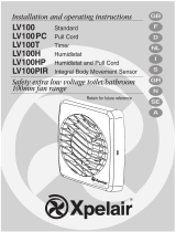
B
C
A
E
D

G
H1
H3
H4
H2
F

Xpelair WX6EC
Installation and Operating Instructions
This appliance can be used by children aged from 8 years and
above and persons with reduced physical, sensory or mental
capabilities or lack of experience and knowledge if they have
been given supervision or instruction concerning the use of the
appliance in a safe way and understand the hazards involved.
Children shall not play with the appliance.
Cleaning and user maintenance of the appliance shall not be
made by children.
Before any cleaning or maintenance, isolate the fan
completely from the mains supply.
This appliance is intended for connection to fixed
wiring.
Check that the electrical rating shown on the fan
matches the mains supply - Fig. F (9).
THIS APPLIANCE IS DOUBLE INSULATED AND
DOES NOT REQUIRE AN EARTH.
All installations must be supervised by a qualified
electrician.
Installations and wiring must conform to current IEE
Regulations (UK), local or appropriate regulations
(other countries). It is the installer’s responsibility to
ensure that the appropriate Building Codes of
Practice are adhered to.
The WX6EC fan has the following features:
• Wall/Panel mounting options.
• Trickle ventilation setting.
• Fitted with silent operation back draught shutters.
• For remote switch operation.
• Single speed extract operation.
• A means for disconnection in all poles must be
incorporated in the fixed wiring in accordance with the
wiring regulations.
• If metal switch boxes are used, earthing
regulations must be followed.
• Circular 2-core cable of a minimum 0.75mm² with a
diameter not less than 5.5mm (Product is double
insulated and does not require an Earth).
• 6mm blade large screwdriver, 3mm blade electrician’s
screwdriver and No. 1 & 2 Pozidriv screwdrivers.
• Masonry drill, hammer & chisel.
• Extendible wall tube, WK6 for walls deeper than
11”/290mm. Available in 300mm or 450mm length.
If installing the fan with an on/off switch:
• On/Off switch
• Locate it as high as possible.
• At least 200mm from the edge of the wall to the centre
of the hole.
• As far away as possible from and opposite to the main
source of air replacement to ensure airflow across the
room (e.g. opposite the internal doorway).
• Near the source of steam or odours.
• Not where ambient temperatures are likely to
exceed 50°C.
• If installed in a kitchen, fans must not be mounted
immediately above a cooker hob or eye level grill.
• When the fan is installed in a room containing a fuel
burning appliance, precautions must be taken to
avoid the backflow of gasses into the room from
the open flue of the burning appliance.
• When intended for use in possible chemical
corrosive atmospheres, consult our Technical
Service Department. (For overseas market contact
your local Xpelair distributor).
• This electrical product, if installed in a shower
room or bathroom must be situated so that it
cannot be touched by persons making use of the
bath or shower.
1. Description
2. What the installer will need
3. Where to locate the fan

1. Check there are no buried pipes or cables e.g.
electricity, gas, water behind the switch location (In
the panel or above the ceiling).
2. Lay in the cable from the isolating switch to the fan
location via the on/off switch if required.
3. Lay in the cable from the isolating switch to the point
of connection to the mains supply.
WARNING: DO NOT MAKE ANY CONNECTIONS TO
THE ELECTRICAL SUPPLY AT THIS STAGE.
4. Install the isolating switch and the on/off switch if
required.
5. Make all connections within the isolating switch and
the on/off switch if required.
Note: Switches must be situated so that they cannot
be touched by persons making use of the bath or
shower.
For Australia only
These models are permanently connected to the supply
and operation is controlled by a remote switch. They
should be directly wired to the supply through an
approved 10A wall mounted surface switch with at least
3mm clearance between contacts.
If working above ground floor level, appropriate
safety precautions must be observed.
WARNING: EYE PROTECTION MUST BE WORN
DURING ALL DRILLING OPERATIONS.
For Installing in a wall
1. Check there are no buried pipes or cables in the
wall or obstructions on the outside e.g. electricity,
gas, water.
2. Make sure that the centre of the hole is located at least
200mm from the edge of the wall.
3. Mark the outline of the hole on the wall (for hole
dimensions see Fig A).
4. Drill pilot holes around edge of the cutting line.
5. Cut through the plaster using a hammer and chisel.
6. Cut through the inner wall using a cold chisel or brick
bolster. Do not cut right through.
7. Go outside and cut a hole in the outer wall ensuring
alignment
1. Remove the inner grille assembly by removing the two
screws Fig. F (10) securing the inner grille assembly to
the fan mounting box.
2. Remove the two screws securing the fan assembly to
the fan mounting box.
If working above ground floor level, appropriate
safety precautions must be observed.
1. Insert the two colour matching Screw Covers (packed
separately) in the fixing holes of the Outer Grille, the
fixing holes are not used on the outer grille.
2. Secure the two ladder strips to the Outer Grille by
positioning them over the hook mouldings (packed
separately) and snapping these into position (Fig. B).
3. Hold the Outer Grille up to the outside of the wall
ensuring the ladder strips protrude through to the interior.
4. Offer up the fan mounting box to the inner wall face
and locate ladder strips into their location fixings (Fig. D).
5. Pull the ladder strips through, locate the wall box in the
wall and screw worm screws into position. Do not
overtighten the screws. Cut away any excess ladder
strip remaining. If necessary, apply a sealing mastic (not
supplied) to the flanges of the Fan Mounting Box and
Outer Grille. This will provide additional seals and take
out any unevenness on both wall faces.
6. Assemble wall tube by slotting the four sections
together (Fig. E)
7. Push the wall tube through the hole in the fan
mounting box and locate on the Outer Grille.
8. The cavity wall tube must be cut flush with the inner
face of the fan mounting box. Mark off and cut away any
excess wall tube and re-install. When installed, the wall
box must slope slightly downwards towards the outer
grille.
9. Position and secure the fan duct assembly into the fan
mounting box, using the fixing screws. Do not
overtighten the screws.
1. Wire the switch cable into the fan’s terminal connector
as shown in Fig. C.
a. If the Fan is wired from above, remove the fan’s
Terminal cover and feed the cable through the top cable
entry. Ensure the outer sheath of the cable is retained in
the labyrinth Fig. C.
b. If wiring from the rear, remove the fan’s terminal
cover and rear entry knockout, feed the cable through the
knockout.
2. Refit and secure the terminal cover.
3. Refit the inner grille to the fan mounting box, using
fixing screws Fig. F (10). Do not overtighten screws.
4. Insert two colour matching screw covers in the fixing
holes in the inner grille. When removing the covers, place
a 3mm blade electrician’s screwdriver into the slot and
lever off the cover.
5. Switch off the mains electrical supply and remove
fuses.
6. Connect the cable from isolation switch to the
electrical supply wiring.
7. Replace the fuses, and switch on the mains electrical
supply.
For fixed wiring circuits the protective fuse for the
appliance must not exceed 5A.
This fan is single speed and non-reversible (extract only).
Switch operated:
• To switch on and off, use the switch on the wall or
ceiling.
• The shutters have a time delay of up to 1 minute on
opening, and up to 3 minutes on closing. Activated by
4. Installing the switches and cables
5. Preparing the hole
6. Separating the inner grille and fan from mounting
box
7. Mounting the fan mounting box
8. Wire the electrical connections
9. Operating the fan

operation of the switch, the delay ensures quiet
operation.
For Australia only:
WARNING – Children should not play with the
appliance. Young children and the infirm should be
supervised
Trickle ventilation
Trickle ventilation is equivalent to that provided by an air
brick or similar device.
1. Remove the Inner grille and back draught shutter (see
‘Mounting the fan in the hole’ section).
To allow trickle ventilation:
2. HOLD THE SHUTTER VANES FULLY OPEN.
3. Push down firmly on the trickle vent catch until it clicks
into position then release the shutter vanes. (See Fig. G).
To fully close the shutters and stop any back draught
4. Pull the trickle vent catch towards you until it clicks into
position.
5. Refit the Inner grille and back draught shutter,
ensuring that the actuator lever is in the “fully down”
position.
A QUALIFIED ELECTRICIAN MUST CARRY OUT ALL
CLEANING.
NOTE: THE FAN WILL CONTINUE TO OPERATE
WITH THE INNER GRILLE ASSEMBLY REMOVED,
HENCE IT MUST BE ISOLATED COMPLETELY FROM
THE MAINS BEFORE ANY WORK IS CARRIED OUT.
1. Before cleaning, isolate the fan completely from
the mains supply. Allow 3 minutes for the impeller to
stop and the powered shutter to close.
2. Remove the inner grille and back-draught shutter by
removing the two screw covers and the screws securing
the inner grille assembly to the fan mounting box Fig. F
(10). To remove the backdraft shutter lay the inner grille
face down and pull shutter assembly upwards Fig. H1
and H2.
3. To clean the impeller, wipe it with a damp, lint free
cloth. Do not use strong detergents or chemical
cleaners.
4. Clean the back draught shutter, and inner grille by
immersing in warm soapy water. Dry thoroughly.
Do not immerse the fan in water or other liquids to
clean any other parts of the fan.
5. Refit the backdraft shutter Fig. H3 and H4.
6. Refit the inner grille assembly and secure with the two
fixing screws. Do not overtighten the screws.
7. Refit the screw covers.
• Never use strong solvents to clean the fan.
• Apart from cleaning, no other maintenance is
required.
Components
1. Inner Grille
2. Fan assembly
3. Outer Grille
4. Trickle vent catch
5. Wall Tube
6. Fan mounting box
7. Back draught shutter
8. Terminal cover
9. Rating Plate
10. Screws (M4 x 10mm long)
11. Worm Screws
12. Ladder Strips
10. Maintenance

Xpelair WX6EC
Instructions d’installation et d’utilisation
Cet appareil peut être utilisé par des enfants âgés de 8 ans ou
plus et des personnes avec des capacités physiques,
sensorielles ou mentales réduites, ou manquant d’expérience
et de connaissances, si ceux-ci disposent d’une supervision
ou d’instructions quant à l’utilisation en toute sécurité de
l’appareil et comprennent les risques en cause.
Les enfants ne doivent pas jouer avec l’appareil.
Le nettoyage et l’entretien par l’utilisateur de l’appareil ne
doivent pas être effectués par des enfants.
Avant tout nettoyage ou entretien, isolez complètement le
ventilateur de l’alimentation secteur.
Cet appareil est prévu pour être connecté à un
câblage fixe.
Vérifiez que les caractéristiques électriques
indiquées sur le ventilateur correspondent à
l’alimentation secteur - figure F (9).
CET APPAREIL EST DOUBLEMENT ISOLÉ ET NE
NÉCESSITE PAS DE MISE À LA TERRE.
Toute installation doit être supervisée par un
électricien qualifié.
L’installation et le câblage doivent être conformes à
la réglementation de câblage IEE en vigueur
(Royaume-Uni), aux règlements locaux ou
appropriés (autres pays). Il incombe à l’installateur
de veiller au respect des codes de pratique du
bâtiment appropriés.
Le ventilateur WX6EC dispose des caractéristiques
suivantes :
• Options de montage sur mur/panneau.
• Réglage de la ventilation à faible écoulement d’air.
• Équipé d’obturateurs à tirage arrière à fonctionnement
silencieux.
• Pour fonctionnement à interrupteur à distance.
• Fonctionnement à vitesse unique d’extraction.
• Un moyen de déconnection à tous les pôles doit être
incorporé au câblage fixe conformément aux
règlements de câblage.
• Si des boîtes de commutation métalliques sont
utilisées, les règlements de mise à la terre doivent
être respectés.
• Câble circulaire à 2 conducteurs d’un minimum de
0,75 mm² avec un diamètre d’au moins 5,5 mm (le
produit est doublement isolé et ne nécessite pas de
mise à la terre).
• Un grand tournevis avec une lame de 6 mm, un
tournevis d’électricien avec une lame de 3 mm et des
tournevis Pozidriv n° 1 et 2.
• Une perceuse à maçonnerie, un marteau et un ciseau.
• Un conduit mural extensible, WK6 pour les murs d’une
profondeur de plus de 11”/290 mm. Disponible en
longueur de 300 mm ou 450 mm.
Si le ventilateur est installé avec un interrupteur
marche/arrêt :
• Un interrupteur marche/arrêt.
• Placez-le aussi haut que possible.
• Avec au moins 200 mm entre le bord du mur et le
centre du trou.
• Aussi loin que possible et à l’opposé de la source
principale de renouvellement d’air pour veiller à un bon
flux d’air dans toute la pièce (par ex. en face d’une
porte interne).
• Près de la source de vapeur ou d’odeurs.
• Pas à un endroit où les températures ambiantes
sont susceptibles de dépasser 50 °C.
• Si vous les installez dans une cuisine, les
ventilateurs ne doivent pas être montés juste au-
dessus d’une plaque de cuisson ou d’un gril à
hauteur des yeux.
• Lorsque le ventilateur est installé dans une pièce
contenant un appareil brûlant du carburant, des
précautions doivent être prises afin d’éviter un
1. Description
2. Ce dont l’installateur aura besoin
3. Où placer le ventilateur

reflux de gaz dans la pièce provenant du conduit
ouvert de l’appareil.
• Lorsque vous avez l’intention d’utiliser le
ventilateur dans des atmosphères potentiellement
chimiques et corrosives, veuillez consulter notre
département des services techniques. (Pour les
marchés à l’étranger, veuillez contacter votre
distributeur Xpelair local).
• Ce produit électrique, s’il est installé dans une salle
de douche ou une salle de bain, doit être situé de
sorte à ne pas pouvoir être touché par les
personnes qui utilisent la baignoire ou la douche.
1. Vérifiez qu’il n’y a aucun tuyau ou câble enfoui
(par ex. électricité, gaz, eau) derrière l’emplacement
de l’interrupteur (dans le panneau ou au-dessus du
plafond).
2. Posez le câble allant de l’interrupteur d’isolement à
l’emplacement du ventilateur en passant par
l’interrupteur marche/arrêt au besoin.
3. Posez le câble allant de l’interrupteur d’isolement au
point de connexion à l’alimentation secteur.
AVERTISSEMENT : NE FAITES AUCUN
RACCORDEMENT À L’ALIMENTATION
ÉLECTRIQUE À CE STADE.
4. Installez l’interrupteur d’isolement et l’interrupteur
marche/arrêt au besoin.
5. Faites tous les raccordements au sein de l’interrupteur
d’isolement et de l’interrupteur marche/arrêt au besoin.
Remarque : Les interrupteurs doivent être placés de
sorte à ne pas pouvoir être touchés par les
personnes utilisant la baignoire ou la douche.
Pour l’Australie uniquement
Ces modèles sont connectés en permanence à
l’alimentation et leur fonctionnement est contrôlé par un
interrupteur à distance. Ils doivent être directement
raccordés à l’alimentation par le biais d’un interrupteur
mural en surface de 10 A agréé avec un espace d’au
moins 3 mm entre les contacts.
Si vous travaillez au-dessus du niveau du sol, vous
devez prendre des précautions de sécurité
appropriées.
AVERTISSEMENT : VOUS DEVEZ PORTER UNE
PROTECTION OCULAIRE LORS DE TOUTES LES
OPÉRATIONS DE FORAGE.
Pour l’installation dans un mur
1. Vérifiez qu’il n’y a aucun tuyau ou câble enfoui
dans le mur ou obstruction à l’extérieur (par ex.
électricité, gaz, eau).
2. Assurez-vous que le centre du trou se trouve à au
moins 200 mm du bord du mur.
3. Dessinez le contour du trou sur le mur (pour les
dimensions du trou, voir la figure A).
4. Percez des avant-trous autour du bord de la ligne de
découpe.
5. Coupez à travers le plâtre à l’aide d’un marteau et d’un
ciseau.
6. Coupez à travers le mur interne à l’aide d’un ciseau à
froid ou d’un ciseau à brique. Ne transpercez pas le mur.
7. Allez à l’extérieur et coupez un trou dans le mur
extérieur en veillant à ce qu’il soit aligné.
1. Retirez l’ensemble de la grille intérieure en retirant les
deux vis, figure F (10), en attachant l’ensemble de la
grille intérieure au boîtier de montage du ventilateur.
2. Retirez les deux vis retenant l’ensemble du ventilateur
au boîtier de montage du ventilateur.
Si vous travaillez au-dessus du niveau du sol, vous
devez prendre des précautions de sécurité
appropriées.
1. Insérez les deux cache-vis de la même couleur
(emballées séparément) dans les trous de fixation de la
grille extérieure, les trous de fixation ne sont pas utilisés
sur la grille extérieure.
2. Attachez les deux crémaillères à la grille extérieure en
les plaçant sur les moulages crochets (emballés
séparément) et en enclenchant ces derniers en place
(figure B).
3. Tenez la grille extérieure contre l’extérieur du mur en
veillant à ce que les crémaillères dépassent à l’intérieur.
4. Positionnez le boîtier de montage du ventilateur sur la
face du mur intérieur et trouvez les crémaillères dans
leurs fixations d’emplacement (figure D).
5. Tirez les crémaillères au travers, trouvez le boîtier
mural dans le mur et vissez les vis sans fin en place. Ne
serrez pas trop les vis. Coupez l’excédent de
crémaillère restant. Au besoin, appliquez un mastic
d’étanchéité (non fourni) sur les rebords du boîtier de
montage du ventilateur et la grille extérieure. Il en
résultera des joints d’étanchéité supplémentaires et
éliminera toute irrégularité sur les deux faces du mur.
6. Assemblez le conduit mural en emboîtant les quatre
sections ensemble (figure E).
7. Poussez le conduit mural à travers le trou dans le
boîtier de montage du ventilateur et positionnez-le sur la
grille extérieure.
8. Le conduit pour mur creux doit être coupé au même
niveau que la face intérieure du boîtier de montage du
ventilateur. Marquez et coupez tout excédent du conduit
mural et ré-installez-le. Lorsque vous l’installez, le boîtier
mural doit être légèrement incliné vers le vers bas vers
la grille extérieure.
9. Positionnez et attachez l’ensemble du conduit du
ventilateur au boîtier de montage du ventilateur à l’aide
des vis de fixation. Ne serrez pas trop les vis.
1. Reliez le câble de l’interrupteur au connecteur de
borne du ventilateur comme illustré sur la figure C.
a. Si le ventilateur est connecté par le dessus, retirez le
cache-bornes du ventilateur et faites passer le câble à
travers l’entrée de câble supérieure. Assurez-vous que
la gaine extérieure du câble est conservée dans le
labyrinthe, figure C.
4. Installation des interrupteurs et des câbles
5. Préparation du trou
6. Séparation de la grille intérieure et ventilateur du
boîtier de montage
7. Montage du boîtier de montage du ventilateur
8. Connexion des raccordements électriques
9.

b. Si vous le connectez par l’arrière, retirez le cache-
bornes du ventilateur et l’entrée arrière sectionnable,
faites passer le câble par l’entrée sectionnable.
2. Remettez et fixez le cache-bornes.
3. Remettez la grille intérieure sur le boîtier de montage
du ventilateur à l’aide des vis de fixation, figure F (10).
Ne serrez pas trop les vis.
4. Insérez les deux cache-vis de la même couleur dans
les trous de fixation sur la grille intérieure. Lorsque vous
retirez les caches, mettez un tournevis d’électricien avec
une lame de 3 mm dans la fente et retirez le cache en
soulevant.
5. Éteignez l’alimentation électrique du secteur et
retirez les fusibles.
6. Connectez le câble de l’interrupteur d’isolement au
câblage de l’alimentation électrique.
7. Remettez les fusibles et allumez l’alimentation
électrique du secteur.
Pour les circuits de câblage fixe, le fusible de
protection de l’appareil ne doit pas dépasser 5 A.
Ce ventilateur est à vitesse unique et non réversible
(extraction uniquement).
Commande par interrupteur :
• Pour l’allumer et l’éteindre, utilisez l’interrupteur sur le
mur ou au plafond.
• Les obturateurs disposent d’une temporisation allant
jusqu’à 1 minute à l’ouverture et jusqu’à 3 minutes à la
fermeture. Activé par le fonctionnement de
l’interrupteur, le délai veille à un fonctionnement
silencieux.
Pour l’Australie uniquement :
AVERTISSEMENT : Les enfants ne doivent pas jouer
avec l’appareil. Les jeunes enfants et les infirmes
doivent être surveillés.
Ventilation à faible écoulement d’air
La ventilation à faible écoulement d’air est équivalente à
celle fournie par une brique creuse ou un dispositif
similaire.
1. Retirez la grille intérieure et l’obturateur de tirage
arrière (voir la section « Montage du ventilateur dans le
trou »).
Pour permettre la ventilation à faible écoulement
d’air :
2. MAINTENEZ LES AUBES DE L’OBTURATEUR
ENTIÈREMENT OUVERTES.
3. Poussez fermement sur le loquet d’évent à faible
écoulement d’air jusqu’à ce qu’il s’enclenche en place,
puis relâchez les aubes de l’obturateur (voir la figure G).
Pour complètement fermer les obturateurs et
arrêter tout tirage arrière
4. Tirez le loquet d’évent à faible écoulement d’air vers
vous jusqu’à ce qu’il s’enclenche en place.
5. Remettez la grille intérieure et l’obturateur de tirage
arrière en veillant à ce que le levier d’actionnement soit
à la position « complètement vers le bas ».
UN ÉLECTRICIEN QUALIFIÉ DOIT EFFECTUER
TOUT LE NETTOYAGE.
REMARQUE : LE VENTILATEUR CONTINUERA À
FONCTIONNER AVEC L’ENSEMBLE DE LA GRILLE
INTÉRIEURE RETIRÉ, IL DOIT DONC ÊTRE
COMPLÈTEMENT ISOLÉ DU SECTEUR AVANT
D’EFFECTUER TOUT TRAVAIL.
1. Avant le nettoyage, isolez complètement le
ventilateur de l’alimentation secteur. Attendez 3
minutes que la roue s’arrête et que l’obturateur
alimenté se ferme.
2. Retirez la grille intérieure et l’obturateur de tirage
arrière en retirant les deux cache-vis et les vis retenant
l’ensemble de la grille intérieure au boîtier de montage
du ventilateur, figure F (10). Pour retirer l’obturateur de
tirage arrière, posez la grille intérieure face vers le bas et
tirez l’ensemble de l’obturateur vers le haut, figures H1
et H2.
3. Pour nettoyer la roue, essuyez-la avec un chiffon
humide non pelucheux. N’utilisez pas de détergents
puissants ou de produits de nettoyage chimiques.
4. Nettoyez l’obturateur de tirage arrière et la grille
intérieure en les plongeant dans de l’eau chaude
savonneuse. Séchez-les bien.
Ne plongez pas le ventilateur dans l’eau ou d’autres
liquides pour nettoyer tout autre élément du
ventilateur.
5. Remettez l’obturateur de tirage arrière, figures H3 et
H4.
6. Remettez l’ensemble de la grille intérieure et attachez-
le avec les deux vis de fixation. Ne serrez pas trop les
vis.
7. Remettez les cache-vis.
• N’utilisez jamais de solvants puissants pour
nettoyer le ventilateur.
• Mis à part le nettoyage, aucun autre entretien n’est
nécessaire.
Composants
1. Grille intérieure
2. Ensemble du ventilateur
3. Grille extérieure
4. Loquet d’évent à faible écoulement d’air
5. Conduit mural
6. Boîtier de montage du ventilateur
7. Obturateur de tirage arrière
8. Cache-bornes
9. Plaque signalétique
10. Vis (M4 x longues de 10 mm)
11. Vis sans fin
12. Crémaillères
9. Fonctionnement du ventilateur
10. Entretien

Xpelair WX6EC
Installations- und Bedienungsanleitung
Dieses Gerät kann von Kindern ab 8 Jahren und von
Personen mit eingeschränkten körperlichen, sensorischen
oder geistigen Fähigkeiten oder mangelnden Erfahrungen
oder Kenntnissen benutzt werden, wenn sie eine Aufsicht
oder Anweisungen über den sicheren Gebrauch des Gerätes
erhalten haben und die damit verbundenen Gefahren
verstehen.
Kinder dürfen nicht mit dem Gerät spielen.
Reinigung und Benutzerwartung des Gerätes darf nicht von
Kindern durchgeführt werden.
Trennen Sie den Lüfter vor jeder Reinigung oder Wartung
vollständig vom Stromnetz.
Dieses Gerät ist zum Anschluss an eine feste
Verkabelung vorgesehen.
Überprüfen Sie, ob die auf dem Lüfter angegebene
elektrische Leistung mit der Netzspannung
übereinstimmt – Abb. F (9).
DIESES GERÄT IST DOPPELT ISOLIERT UND
BENÖTIGT KEINE ERDE.
Alle Installationen müssen von einer qualifizierten
Elektrofachkraft überwacht werden.
Installationen und Verkabelungen müssen den
aktuellen IEE-Vorschriften (UK) und den örtlichen
Vorschriften oder den entsprechenden Vorschriften
(andere Länder) entsprechen. Es liegt in der
Verantwortung des Installateurs, sicherzustellen, dass
die entsprechenden Bauvorschriften eingehalten
werden.
Der WX6EC-Lüfter hat folgende Merkmale:
• Optionen für die Wand-/Paneelmontage.
• Riesellüftungseinstellung.
• Geräuscharme Rückzugverschlüsse.
• Für Fernschalterbetrieb.
• Eingeschwindigkeits-Extraktionsbetrieb.
• In der festen Verdrahtung ist eine allpolige
Trennmöglichkeit nach den Verdrahtungsregeln
einzubauen.
• Bei Verwendung von Metallschaltkästen sind die
Erdungsvorschriften zu beachten.
• Rundes 2-adriges Kabel mit einem Durchmesser von
mindestens 0,75 mm² und einem Durchmesser von
mindestens 5,5 mm (Produkt ist doppelt isoliert und
benötigt keine Erdung).
• Großer Schraubendreher mit 6 mm Klinge, Elektriker-
Schraubendreher mit 3 mm Klinge und Pozidriv-
Schraubendreher Nr. 1 und 2.
• Mauerbohrer, Hammer und Meißel.
• Verlängerbares Wandrohr, WK6 für Wände ab 11"/290
mm Tiefe. Erhältlich in 300 mm oder 450 mm Länge.
Bei Installation des Lüfters mit einem Ein-/Ausschalter:
• Ein-/Ausschalter
• Bringen Sie ihn so hoch wie möglich an.
• Mindestens 200 mm vom Rand der Wand bis zur Mitte
des Lochs.
• So weit wie möglich von und gegenüber der Haupt-
Zuluftquelle, um Luftstrom durch den Raum zu
gewährleisten (z. B. gegenüber der Innentür).
• In der Nähe der Dampf- oder Geruchsquelle.
• Nicht dort, wo die Umgebungstemperaturen 50°C
überschreiten können.
• Bei Einbau in eine Küche dürfen Lüfter nicht
unmittelbar über einer Kochstelle oder einem Grill auf
Augenhöhe montiert werden.
• Wenn der Lüfter in einem Raum installiert wird, der
ein Gerät zur Verbrennung von Brennstoffen enthält,
müssen Vorkehrungen zur Verhinderung des
Rückströmens von Gasen aus dem offenen
Rauchabzug des Verbrennungsgeräts in den Raum
getroffen werden.
1. Beschreibung
2. Was der Installateur benötigt
3. Wo der Lüfter anzubringen ist

• Vor der Verwendung in möglicherweise chemisch
korrosiven Atmosphären lassen Sie sich bitte von
unserer technischen Serviceabteilung beraten. (Für
ausländische Märkte wenden Sie sich an Ihren
örtlichen Xpelair-Händler).
• Wenn dieses elektrische Produkt in einem
Duschraum oder Badezimmer installiert wird, muss
es so platziert sein, dass es von Personen, die die
Badewanne oder Dusche benutzen, nicht berührt
werden kann.
1. Überprüfen Sie, dass sich hinter der
Schalterposition (im Paneel oder über der Decke) keine
verborgenen Rohre oder Kabel wie beispielsweise für
Strom, Gas oder Wasser befinden.
2. Verlegen Sie das Kabel vom Trennschalter über den Ein-
/Ausschalter zur Lüfterposition, falls erforderlich.
3. Verlegen Sie das Kabel vom Trennschalter bis zur
Anschlussstelle an die Stromversorgung.
WARNUNG: STELLEN SIE IN DIESEM STADIUM KEINE
VERBINDUNGEN ZUR STROMVERSORGUNG HER.
4. Installieren Sie den Trennschalter und den Ein-
/Ausschalter, falls erforderlich.
5. Stellen Sie alle Verbindungen innerhalb des
Trennschalters und innerhalb des Ein-/Ausschalters her,
falls erforderlich.
Hinweis: Schalter müssen so angebracht sein, dass sie
von Personen nicht berührt werden können, die die
Badewanne oder die Dusche benutzen.
Nur für Australien
Diese Modelle sind fest mit der Stromversorgung
verbunden und der Betrieb wird über einen Fernschalter
gesteuert. Sie sollten direkt über einen zugelassenen 10-A-
Wandschalter mit 3 mm Mindestabstand zwischen den
Kontakten an die Stromversorgung angeschlossen werden.
Bei Arbeiten über Grund sind angemessene
Sicherheitsmaßnahmen zu befolgen.
WARNUNG: BEI ALLEN BOHRARBEITEN MUSS EIN
AUGENSCHUTZ GETRAGEN WERDEN.
Zum Einbau in eine Wand
1. Überprüfen Sie, dass sich keine verborgenen Rohre
oder Kabel in der Wand oder Hindernisse an der
Außenseite wie beispielsweise Strom-, Gas-,
Wasserleitungen befinden.
2. Stellen Sie sicher, dass die Mitte des Lochs mindestens
200 mm vom Rand der Wand entfernt ist.
3. Markieren Sie den Umriss des Lochs an der Wand
(Lochabmessungen siehe Abb. A).
4. Bohren Sie Pilotlöcher um den Rand der Schneidlinie.
5. Stemmen Sie mit Hammer und Meißel durch den Putz.
6. Stemmen Sie durch die Innenwand mit einem Flach-
oder Breitmeißel. Stemmen Sie nicht ganz durch.
7. Gehen Sie nach außen und stemmen Sie ein Loch in die
Außenwand, um die richtige Ausrichtung sicherzustellen.
1. Entfernen Sie die Innengitterbaugruppe, indem Sie die
beiden Schrauben Abb. F (10) entfernen, mit denen die
Innengitterbaugruppe am Lüftermontagekasten befestigt
ist.
2. Entfernen Sie die beiden Schrauben, mit denen die
Lüfterbaugruppe am Lüftermontagekasten befestigt ist.
Bei Arbeiten über Grund sind angemessene
Sicherheitsmaßnahmen zu befolgen.
1. Setzen Sie die beiden farblich passenden
Schraubenabdeckungen (separat verpackt) in die
Befestigungslöcher des Außengitters ein. Die
Befestigungslöcher am Außengitter werden nicht
verwendet.
2. Befestigen Sie die beiden Leiterstreifen am Außengitter,
indem Sie diese über die Haken-Formteile legen (separat
verpackt) und in Position einrasten lassen (Abb. B).
3. Halten Sie das Außengitter an die Außenseite der Wand
und achten Sie darauf, dass die Leiterstreifen in den
Innenraum hineinragen.
4. Setzen Sie den Lüftermontagekasten an die innere
Wandfläche und bringen Sie die Leiterstreifen an ihre
Befestigungspunkte (Abb. D).
5. Ziehen Sie die Leiterstreifen durch, lokalisieren Sie den
Mauerkasten in der Wand und schrauben Sie die
Schneckenschrauben fest. Ziehen Sie die Schrauben
nicht zu fest an. Schneiden Sie überschüssige
Leiterstreifen ab. Bringen Sie bei Bedarf einen Dichtmastix
(nicht im Lieferumfang enthalten) auf die Flansche des
Lüftermontagekastens und des Außengitters auf. Dadurch
wird zusätzliche Abdichtung erreicht und Unebenheiten an
beiden Wandflächen werden ausgeglichen.
6. Montieren Sie das Wandrohr, indem Sie die vier Teile
zusammenstecken (Abb. E).
7. Schieben Sie das Wandrohr durch das Loch im
Lüftermontagekasten und positionieren Sie es am
Außengitter.
8. Das Hohlwandrohr muss bündig mit der Innenseite des
Lüftermontagekastens abgeschnitten werden. Markieren
Sie überschüssiges Wandrohr, schneiden Sie es ab und
installieren Sie es wieder. Im eingebauten Zustand muss
der Mauerkasten zum Außengitter hin leicht abfallen.
9. Positionieren Sie die Lüfterkanalbaugruppe im
Lüftermontagekasten und sichern Sie sie mit den
Befestigungsschrauben. Überdrehen Sie die Schrauben
nicht.
1. Verdrahten Sie das Schalterkabel in die
Klemmenanschlüsse wie in Abb. C dargestellt.
a. Wenn der Lüfter von oben verdrahtet wird, entfernen
Sie die Klemmenabdeckung des Lüfters und führen Sie das
Kabel durch die obere Kabeleinführung. Stellen Sie sicher,
dass der Außenmantel des Kabels im Labyrinth Abb. C
gehalten wird.
b. Wenn die Verkabelung von hinten erfolgt, entfernen Sie
die Klemmenabdeckung des Lüfters und die
4. Installation der Schalter und Kabel
5. Vorbereitung des Lochs
6. Trennung von Innengitter und Lüfter vom
Montagekasten
7. Installation des Lüftermontagekastens
8. Verdrahtung der elektrischen Anschlüsse

Ausbrechöffnung der hinteren Einführung und führen Sie
das Kabel durch die Ausbrechung.
2. Befestigen Sie die Klemmenabdeckung wieder und
sichern Sie sie.
3. Befestigen Sie das Innengitter mit den
Befestigungsschrauben Abb. F (10) wieder am
Lüftermontagekasten. Überdrehen Sie die Schrauben
nicht.
4. Setzen Sie zwei farblich passende
Schraubenabdeckungen in die Befestigungslöcher im
Innengitter ein. Stecken Sie zum Entfernen der
Abdeckungen einen Elektriker-Schraubendreher mit 3 mm
Klinge in den Schlitz und hebeln Sie die Abdeckung ab.
5. Schalten Sie die Netzstromversorgung aus und
entfernen Sie die Sicherungen.
6. Schließen Sie das Kabel vom Trennschalter an die
Stromversorgung an.
7. Setzen Sie die Sicherungen wieder ein und schalten Sie
die Stromversorgung ein.
Bei festverdrahteten Schaltungen darf die
Schutzsicherung für das Gerät 5 A nicht überschreiten.
Dieser Lüfter hat nur eine Geschwindigkeit und ist nicht
umkehrbar (nur Absaugung).
Schalterbetrieb:
• Verwenden Sie zum Ein- und Ausschalten den Schalter
an der Wand oder der Decke.
• Die Klappen haben eine Zeitverzögerung von bis zu 1
Minute beim Öffnen und bis zu 3 Minuten beim Schließen.
Die Verzögerung wird durch Betätigen des Schalters
aktiviert und sorgt für einen leisen Betrieb.
Nur für Australien:
WARNUNG – Kinder dürfen nicht mit dem Gerät
spielen. Kleine Kinder und schutzbedürftige Personen
sollten beaufsichtigt werden.
Riesellüftung
Rieselbelüftung entspricht der Belüftung durch einen
Lüftungsstein oder eine ähnliche Einrichtung.
1. Entfernen Sie das Innengitter und den
Rückzugverschluss (siehe Abschnitt „Montage des Lüfters
im Loch“).
Zur Ermöglichung von Rieselbelüftung:
2. HALTEN SIE DIE VERSCHLUSSLAMELLEN
VOLLSTÄNDIG GEÖFFNET.
3. Drücken Sie die Riesellüftungssperre fest nach unten,
bis sie einrastet und lassen Sie dann die
Verschlusslamellen los. (Siehe Abb. G.)
Zum vollständigen Schließen der Lamellen und zum
Stoppen von Rückzug:
4. Ziehen Sie die Rieselbelüftungssperre zu sich, bis sie
einrastet.
5. Setzen Sie das Innengitter und den Rückzugverschluss
wieder ein und stellen Sie sicher, dass sich der
Betätigungshebel in der Position „vollständig unten“
befindet.
SÄMTLICHE REINIGUNGSARBEITEN SIND VON EINER
ELEKTROFACHKRAFT DURCHZUFÜHREN.
HINWEIS: DER LÜFTER ARBEITET BEI
ABGENOMMENER INNENGITTERBAUGRUPPE
WEITER, DAHER MUSS ER VOLLSTÄNDIG VOM
STROMNETZ GETRENNT SEIN, BEVOR ARBEITEN
DURCHGEFÜHRT WERDEN.
1. Trennen Sie den Lüfter vor der Reinigung vollständig
vom Stromnetz. Warten Sie 3 Minuten, damit das
Flügelrad zum Stillstand kommen und der
angetriebene Verschluss sich schließen kann.
2. Entfernen Sie das Innengitter und den
Rückzugverschluss, indem Sie die beiden
Schraubenabdeckungen und die Schrauben entfernen, mit
denen die innere Gitterbaugruppe am
Lüftermontagekasten Abb. F (10) befestigt ist. Um den
Rückzugverschluss zu entfernen, legen Sie das Innengitter
nach unten und ziehen Sie die Verschlussbaugruppe nach
oben, Abb. H1 und H2.
3. Um das Flügelrad zu reinigen, wischen Sie es mit einem
feuchten, fusselfreien Tuch ab. Verwenden Sie keine
starken Reinigungsmittel oder chemische Reiniger.
4. Reinigen Sie den Rückzugverschluss und das
Innengitter, indem sie es in warmes Seifenwasser
eintauchen. Danach gründlich abtrocknen.
Tauchen Sie den Lüfter nicht in Wasser oder andere
Flüssigkeiten ein, um irgendwelche anderen Teile des
Lüfters zu reinigen.
5. Setzen Sie den Rückzugverschluss wieder ein, siehe
Abb. H3 und H4.
6. Setzen Sie die innere Gitterbaugruppe wieder ein und
sichern Sie sie mit den beiden Befestigungsschrauben.
Überdrehen Sie die Schrauben nicht.
7. Bringen Sie die Schraubenabdeckungen wieder an.
• Verwenden Sie zum Reinigen des Lüfters niemals
starke Lösungsmittel.
• Außer der Reinigung ist keine weitere Wartung
erforderlich.
Komponenten
1. Innengitter
2. Lüfterbaugruppe
3. Außengitter
4. Riesellüftungsverschluss
5. Wandrohr
6. Lüftermontagekasten
7. Rückzugverschluss
8. Klemmenabdeckung
9. Typenschild
10. Schrauben (M4 x 10 mm lang)
11. Schneckenschrauben
12. Leiterstreifen
9. Betrieb des Lüfters
10. Wartung

Xpelair WX6EC
Istruzioni per l’installazione e il funzionamento
Questa apparecchiatura può essere utilizzata da bambini a
partire dagli 8 anni di età e da persone con abilità fisiche,
sensoriali o mentali ridotte o prive di esperienza e
conoscenze, se supervisionati e istruiti sull’uso sicuro
dell’apparecchiatura e se consapevoli dei pericoli connessi.
I bambini non devono giocare con l’apparecchiatura.
La pulizia e la manutenzione da parte dell’utente
dell’apparecchiatura non deve essere effettuata da bambini.
Prima di effettuare la pulizia o la manutenzione, isolare
completamente la ventola dalla rete elettrica.
Questa apparecchiatura è progettata per essere
collegata al cablaggio fisso.
Controllare che i valori elettrici nominali indicati
sulla ventola corrispondano all’alimentazione
principale - Fig. F (9).
QUESTA APPARECCHIATURA DISPONE DI UN
DOPPIO ISOLAMENTO E NON RICHIEDE UNA
MESSA A TERRA.
Tutte le installazioni devono essere monitorate da un
elettricista qualificato.
Le installazioni e il cablaggio devono essere
conformi alle normative IEE in vigore (nel Regno
Unito), a normative locali o pertinenti in vigore (in
altri paesi). È responsabilità dell’installatore
assicurare che ci si attenga ai Codici di buona
pratica per l’edilizia pertinenti.
La ventola WX6EC ha le seguenti funzionalità:
• Opzioni di montaggio a parete/su pannello.
• Impostazione di microventilazione.
• Dispone di serrande anti-ritorno con funzionamento
silenzioso.
• Funzionamento con interruttore a distanza.
• Singola velocità, sola aspirazione.
• È necessario poter interrompere l’erogazione di
corrente nella rete fissa per tutti i poli in conformità con
le norme di cablaggio.
• Se vengono utilizzate scatole per interruttori
metalliche, devono essere seguite le normative
sulla messa a terra.
• Cavo bipolare circolare di un minimo di 0,75mm² con
un diametro non inferiore a 5,5mm (il Prodotto ha un
doppio isolamento e non richiede una messa a terra).
• Cacciavite a taglio svasato 6mm, cacciavite per
elettricisti a taglio svasato 3mm e cacciaviti a croce
Pozidriv 1 e 2.
• Trapano per muratura, martello, scalpello.
• Tubo da parete allungabile, WK6 per pareti di uno
spessore superiore a 290mm. Disponibile con una
lunghezza di 300mm o 450mm.
In caso di installazione della ventola con un interruttore
di accensione/spegnimento:
• Interruttore di accensione/spegnimento
• Posizionarla il più in alto possibile.
• Ad almeno 200mm dal bordo della parete al centro del
foro.
• Il più lontano possibile e sul lato opposto rispetto alla
fonte principale di ricambio dell’aria, per garantire un
flusso d’aria da una parte all’altra della stanza (ad es.
in posizione opposta rispetto a una porta interna).
• Vicino alla fonte di vapore o odore.
• Non in ambienti dove è probabile che le
temperature superino i 50°C.
• Se installata in una cucina, la ventola non deve
essere montata immediatamente al di sopra di un
fornello o di un grill all’altezza degli occhi.
• Quando la ventola è installata in una stanza
contenente un dispositivo che brucia combustibile,
devono essere prese le dovute precauzioni per
evitare il riflusso di gas nella stanza dall’apertura di
scarico del dispositivo di combustione.
• Se destinata a un utilizzo in atmosfere che
potrebbero contenere agenti chimici corrosivi,
rivolgersi al nostro dipartimento dell’assistenza
tecnica. (Per l’estero contattare il distributore
locale Xpelair).
• Questo prodotto elettrico, se installato in una
stanza da bagno, deve essere posizionato in modo
1. Descrizione
2. Di cosa necessita l’installatore
3. Dove posizionare la ventola

da non entrare in contatto con la persona che
utilizza la doccia o la vasca da bagno.
1. Controllare che non vi siano cavi o condutture ad
es. elettricità, gas, acqua dietro l’ubicazione
dell’interruttore (all’interno del pannello o sopra il
soffitto).
2. Posare il cavo dall’interruttore differenziale alla
posizione della ventola passando per l’interruttore di
accensione/spegnimento se necessario.
3. Posare il cavo dall’interruttore differenziale al punto di
connessione dell’alimentazione principale.
AVVERTENZA: NON EFFETTUARE CONNESSIONI
ALLA RETE ELETTRICA IN QUESTA FASE.
4. Installare l’interruttore differenziale e l’interruttore di
accensione/spegnimento se necessario.
5. Effettuare tutte le connessioni all’interno
dell’interruttore differenziale e dell’interruttore di
accensione/spegnimento se necessario.
Nota: gli interruttori devono essere posizionati in
modo da non entrare in contatto con le persone che
utilizzano la doccia o la vasca da bagno.
Solo per l’Australia
Questi modelli sono sempre connessi alla rete elettrica e
il loro funzionamento è controllato tramite un interruttore
a distanza. Dovrebbero essere collegati direttamente
all’alimentazione tramite un interruttore apposito da
parete da 10A con una distanza di almeno 3mm tra i
contatti.
Se si lavora al di sopra del livello del suolo, devono
essere osservate le precauzioni di sicurezza
adeguate.
AVVERTENZA: GLI OCCHIALI PROTETTIVI DEVONO
ESSERE INDOSSATI DURANTE TUTTE LE
OPERAZIONI DI FORATURA.
Per un’installazione su parete
1. Controllare che non vi siano cavi o condutture
all’interno di una parete od ostacoli al suo esterno ad
es. elettricità, gas, acqua.
2. Assicurarsi che il centro del foro sia situato ad almeno
200mm dai bordi della parete.
3. Segnare il contorno del foro sulla parete (per le
dimensioni dei fori vedere Fig. A).
4. Trapanare i fori pilota attorno al bordo della linea di
taglio.
5. Incidere l’intonaco con un martello e uno scalpello.
6. Incidere la parete interna utilizzando uno scalpello da
ferro o scalpello per mattoni. Non incidere entrambi in
verticale, con un colpo deciso.
7. Andare all’esterno e forare la parete esterna,
mantenendo l’allineamento.
1. Rimuovere il gruppo della griglia interna togliendo le
due viti Fig. F (10) che lo fissano alla scatola da incasso
della ventola.
2. Rimuovere le due viti che fissano il gruppo della
ventola alla scatola da incasso della ventola.
Se si lavora al di sopra del livello del suolo, devono
essere osservate le precauzioni di sicurezza
adeguate.
1. Inserire i due cappucci per viti dello stesso colore (in
una confezione separata) nei fori di fissaggio della
Griglia esterna, i fori di fissaggio non sono utilizzati sulla
griglia esterna.
2. Fissare le due fascette metalliche alla griglia esterna,
posizionandole negli alloggiamenti (in confezione
separata) e incastrandole in posizione corretta (Fig. B).
3. Posizionare la griglia esterna contro la parete esterna,
in modo che le fascette metalliche sporgano all’interno.
4. Alzare la scatola da incasso della ventola verso la
superficie della parete interna e posizionare le fascette
metalliche negli alloggiamenti di fissaggio (Fig. D).
5. Tirare le fascette metalliche negli alloggiamenti,
posizionare la scatola per parete sulla parete e fissarla
avvitando viti senza fine. Non stringere
eccessivamente le viti. Rimuovere qualsiasi parte delle
fascette metalliche in eccesso tagliandola. Se
necessario, applicare del mastice sigillante (non incluso)
alle flange della scatola da incasso della ventola e della
Griglia esterna. Ciò servirà a sigillare ulteriormente il
tutto e pareggerà qualsiasi irregolarità su entrambe le
superfici della parete.
6. Assemblare il tubo da parete incastrando insieme le
quattro sezioni (Fig. E).
7. Spingere il tubo da parete attraverso il foro nella
scatola da incasso della ventola e posizionarlo sulla
griglia esterna.
8. Il tubo da parete per l’incavo deve essere tagliato
perfettamente a filo con la superficie interna della scatola
da incasso della ventola. Segnare e rimuovere
tagliandola qualsiasi parte in eccesso del tubo e
procedere nuovamente all’installazione. Una volta
installata, la scatola da parete deve essere inclinata
leggermente all’ingiù, verso la griglia esterna.
9. Posizionare e fissare il gruppo del condotto della
ventola all’interno della scatola da incasso della ventola,
utilizzando le viti di fissaggio. Non stringere
eccessivamente le viti.
1. Cablare il cavo dell’interruttore nella connessione
terminale della ventola come mostrato in Fig. C.
a. Se il cablaggio della ventola avviene dall’alto,
rimuovere il copriterminale e far passare il cavo
attraverso l’ingresso del cavo superiore. Assicurarsi che
il rivestimento esterno del cavo sia mantenuto nella
struttura, Fig. C.
b. Se il cablaggio avviene dalla parte posteriore,
rimuovere il copriterminale della ventola e il passaggio
4. Installare interruttori e cavi
5. Preparare il foro
6. Separare la griglia interna e la ventola dalla scatola
da incasso
7. Montare la scatola da incasso della ventola
8. Cablare le connessioni elettriche

posteriore, facendo passare il cavo attraverso
quest’ultimo.
2. Riposizionare e fissare il copriterminale.
3. Riposizionare la griglia interna sulla scatola da
incasso della ventola, utilizzando le viti di fissaggio, Fig.
F (10). Non stringere eccessivamente le viti.
4. Inserire i due cappucci per viti (dello stesso colore) sui
fori di fissaggio della griglia interna. Per rimuovere i
cappucci, posizionare un cacciavite per elettricisti a
taglio svasato 3mm nel vano e rimuovere il cappuccio
facendo leva.
5. Spegnere l’interruttore generale e rimuovere i
fusibili.
6. Connettere il cavo dall’interruttore differenziale
all’alimentazione elettrica.
7. Rimettere i fusibili e accendere l’interruttore generale.
Per circuiti di cablaggio fissi, il fusibile di protezione
per le apparecchiature non deve superare i 5A.
Questa ventola è a velocità singola e non reversibile
(sola aspirazione).
Con funzionamento tramite interruttore:
• per l’accensione e lo spegnimento utilizzare
l’interruttore sulla parete o sul soffitto.
• le serrande hanno un ritardo di apertura fino a un
minuto e di chiusura fino a 3 minuti. Attivato mettendo
in funzione l’interruttore, il ritardo garantisce un
funzionamento silenzioso.
Solo per l’Australia:
AVVERTENZA – I bambini non devono giocare con
l’apparecchiatura. I bambini piccoli e i malati devono
essere sotto supervisione costante
Microventilazione
La microventilazione è simile alla ventilazione fornita da
un mattone forato o un dispositivo simile.
1. Rimuovere la griglia interna e la serranda anti-ritorno
(vedere la sezione “Montare la ventola nel foro”).
Per permettere la microventilazione:
2. MANTENERE LE ALETTE DELLA SERRANDA
COMPLETAMENTE APERTE.
3. Spingere in modo deciso verso il basso il fermo di
microventilazione fino a che non clicchi in posizione,
successivamente rilasciare le alette della serranda.
(Vedere Fig. G).
Per chiudere completamente le alette e impedire
qualsiasi riflusso dell’aria
4. Tirare il fermo di microventilazione verso di sé fino a
che non clicchi in posizione.
5. Riposizionare la griglia interna e la serranda anti-
ritorno, assicurandosi che la leva di azionamento sia in
posizione completamente abbassata.
UN ELETTRICISTA QUALIFICATO DEVE
EFFETTUARE TUTTE LE OPERAZIONI DI PULIZIA.
NOTA: LA VENTOLA CONTINUERÀ A FUNZIONARE
UNA VOLTA RIMOSSA LA GRIGLIA INTERNA, DI
CONSEGUENZA DEVE ESSERE ISOLATA
COMPLETAMENTE DALLA RETE ELETTRICA
PRIMA DI EFFETTUARE QUALSIASI OPERAZIONE.
1. Prima di effettuare la pulizia, isolare la ventola
completamente dalla rete elettrica. Attendere 3
minuti affinché la turbina smetta di girare e affinché
si chiuda la serranda.
2. Rimuovere la griglia interna e la serranda anti-ritorno
togliendo i due cappucci per viti e le viti che fissano il
gruppo della griglia interna alla scatola da incasso della
ventola, Fig. F (10). Per rimuovere la serranda anti-
ritorno, posizionare la griglia interna all’ingiù e tirare il
gruppo serranda verso l’alto Fig. H1 e H2.
3. Per pulire la ventola, passare un panno umido privo di
lanugine. Non utilizzare detergenti forti o chimici.
4. Pulire la serranda anti-ritorno e la griglia
immergendole in acqua tiepida e sapone. Asciugare
accuratamente.
Non immergere la ventola in acqua o in altri liquidi al
fine di pulirne qualsiasi parte.
5. Riposizionare la serranda anti-ritorno, Fig. H3 e H4.
6. Riposizionare il gruppo della griglia interna e fissarlo
con le due viti di fissaggio. Non stringere
eccessivamente le viti.
7. Riposizionare i cappucci per viti.
• Non utilizzare mai solventi forti per pulire la
ventola.
• Ad eccezione della pulizia, non è necessaria altra
manutenzione.
Componenti
1. Griglia interna
2. Gruppo della ventola
3. Griglia esterna
4. Fermo di microventilazione
5. Tubo da parete
6. Scatola da incasso della ventola
7. Serranda anti-ritorno
8. Copriterminale
9. Targhetta
10. Viti (M4 x lunghezza di 10mm)
11. Viti senza fine
12. Fascette metalliche
9. Funzionamento della ventola
10. Manutenzione

XPELAIR WX6EC
. .
.
•
.
•
.(
• .
.1
.( .2 . 3 .
. .4. .5 .
.
.
.
.
.1 .
.
.(
. .
:
WX6EC : •. •. •. •. •.
• . •. • .( • . •. •WK6 .
. •
•. •. •
.( •. • 50°. • .
5
.1فصولا
.4
3 4

.
. .2. .3 . 4
3
4 5 6 . 7
.
9 10
10 11 12
6 7 8
7 8 9 10
8 9 10 11 12

.7.

This page has been left blank for the addition any notes you may wish to make.

Warranty
What does an Xpelair Warranty cover?
Xpelair products deliver reliable service for normal, household use in domestic settings. All Xpelair products are individually tested before leaving the factory.
If you are a consumer and you experience a problem with your Xpelair product, which is found to be defective due to faulty materials or workmanship within the
Warranty Period, this Xpelair Warranty will cover repair or - at the discretion of Xpelair – replacement with a functionally equivalent Xpelair product.
The Xpelair Warranty Period is two calendar years with five years on the motor only, from the date of purchase of your Xpelair product, or the date of delivery of the
product, if later. The Xpelair Warranty is conditional upon you providing the original purchase receipt as proof of purchase. Please therefore retain your receipt as
proof of purchase.
If you do experience a problem with your Xpelair product please call the Helpline on +44 [0]344 879 3588 or at the address below.
We will need details of your Xpelair product, and a description of the fault which has occurred. Once we receive your information and proof of purchase we will contact
you to make the necessary arrangements.
Customers outside UK – see international below.
If your Xpelair product is not covered by this Xpelair Warranty there may be a charge to repair your product. However, we will contact you for agreement to any
charges before any chargeable service is carried out.
What is not covered by an Xpelair Warranty?
The Xpelair Warranty does not cover any of the following:
• Any fault or damage to your Xpelair product due to faulty materials or workmanship occurring outside the Warranty Period.
• Any fault or damage occurring to any pre-owned Xpelair product or to any other equipment or property.
• Accidental damage to your Xpelair product or damage to your Xpelair product from external sources (for example, transit, weather, electrical outages or power
surges).
• Fault or damage to your Xpelair product which is:
• Not due to faulty materials or workmanship or which is due to circumstances outside Xpelair’s control.
• Caused by use of your Xpelair product for anything other than normal domestic household purposes in the country where it was purchased.
Important
• Caused by any misuse, abuse or negligent use of the Xpelair product, including but not limited to any failure to use it in accordance with the Operating Instructions
supplied with the product.
• Caused by any failure to assemble, install, clean and maintain your Xpelair product in accordance with the Operating Instructions supplied with the product unless
this was carried out by Xpelair or its authorised dealers.
• Caused by repairs or alterations to your Xpelair product not carried out by Xpelair service personnel or its authorised dealer(s).
• Caused by use of any consumables or spare parts for your Xpelair product which are not Xpelair specified.
Terms and Conditions
• The Xpelair Warranty is valid for Xpelair from the date of purchase of your Xpelair product from a recognised retailer in the country of purchase and use, or the date
of delivery of the product if later, always provided the original receipt has been retained and is produced as proof of purchase.
• You must provide to Xpelair or its authorised agents on request the original receipt as proof of purchase and - if required by Xpelair - proof of delivery. If you are
unable to provide this documentation, you will be required to pay for any repair work required.
• Any repair work under the Xpelair Warranty will be carried out by Xpelair or its authorised dealer(s) and any parts that are replaced will become the property of
Xpelair. Any repairs performed under the Xpelair Warranty will not extend the Warranty Period.
• Any replacement of your Xpelair product by Xpelair during the Warranty Period will start the Warranty Period afresh from the date of delivery of the replacement
Xpelair product to you.
• The Xpelair Warranty does not entitle you to recovery of any indirect or consequential loss or damage including but not limited to loss or damage to any other
property.
• The Xpelair Warranty is in addition to your statutory rights as a consumer and your statutory rights are not affected by this Xpelair Warranty.
Contact Xpelair
If you have any questions about what the Xpelair Warranty covers and does not cover or how to claim under the Xpelair Warranty, please contact us using the
information below.
Contact details
Glen Dimplex UK Ltd, Glen Dimplex Europe Limited,
Millbrook House, Grange Drive, Hedge End, Southampton, SO30 2DF Airport Road, Cloghran, Co. Dublin, K67 VE08.
Telephone: +44 (0) 344 879 3588 Telephone: +353 (0)1 8523400
Email: customer.services@glendimplex.com Email: serviceireland@glendimplex.com
Web: www.xpelair.co.uk
International
• Guarantee: Contact your local distributor or Xpelair direct for details.
• Technical Advice and Service: Contact your local Xpelair distributor.
Xpelair: A brand of Glen Dimplex Heating & Ventilation
© Glen Dimplex. All rights reserved. Material contained in this publication may not be reproduced in whole or in part, without prior permission in writing of Glen
Dimplex
Important
Leaflet Number: 08/100069/0 Rev: B
For electrical products sold within the European Community. At the end of the electrical products useful life it should not be
disposed of with household waste. Please recycle where facilities exist. Check with a Local Authority or retailer for recycling advice
in your country. Batteries should be disposed of or recycled in accordance with WEEE Directive 2012/19/EU. Packaging should be
recycled where possible.
/