Page is loading ...

English..............................................................................................................................3
Deutsch.......................................................................................................................... 30
Italiano............................................................................................................................ 59
Français......................................................................................................................... 88
Español........................................................................................................................ 117
Português.................................................................................................................... 146
Nederlands................................................................................................................. 176
Polski............................................................................................................................ 204
Svenska....................................................................................................................... 232
Suomi............................................................................................................................259
Magyar......................................................................................................................... 286
Русский........................................................................................................................317
Türkçe...........................................................................................................................350
Ελληνικά...................................................................................................................... 379
2

Table of contents
Startup on page 3 Configure the relays on page 15
User interface and navigation on page 5 Set the error hold mode on page 21
Set the language on page 8 Set the security settings on page 21
Remove channels from the measurement screen (2- or
4-channel analyzers) on page 8
Adjust the water level of the overflow vessel
on page 21
Set the display brightness on page 9 Set the auto calibration settings on page 22
Set the maximum rinsing time on page 9 Do a calibration on page 22
Set the sample target pH (analyzer without cationic
pump) on page 9
Show the calibration data on page 24
Set the sample target pH (analyzer with cationic pump)
on page 9
Do a calibration verification on page 24
Set the measurement logging interval (1-channel
analyzers) on page 10
Do a temperature calibration on page 24
Set the measurement logging interval (2- or 4-channel
analyzers) on page 11
Do a flow rate calibration on page 24
Set the reactivation schedule on page 12 Calibrate the 4-20 mA analog outputs on page 25
Set the measurement units on page 12 Show the details of the current and the last
measurement on page 25
Set the signal average on page 12 Measure a grab sample on page 26
Change the analyzer or channel names on page 12 Show the measurement, calibration and event logs
on page 26
Start or stop measurements on a channel (2- or 4-
channel analyzers) on page 13
Save data or settings to an SD card on page 27
Change the channel measurement order (2- or 4-
channel analyzers) on page 13
Install the latest software version on page 28
Set the date and time on page 13 Install the latest HART module firmware on page 29
Configure the 4-20 mA analog outputs on page 13
Safety information
Refer to the installation user manual for general safety information, hazard descriptions and
precautionary labels descriptions.
Startup
Connect the power cord to an electrical outlet with protective earth ground.
English
3

Set the power switch to on
Refer to the illustrated steps that follow.
Complete the startup wizard
1. If the startup wizard does not start automatically, push menu then select SETUP SYSTEM >
STARTUP ANALYZER.
2. Follow the instructions on the display.
• If prompted to set the channel sequence (measurement order), use the UP and DOWN arrows
to select a row, then push the LEFT or RIGHT arrow to select the channel. S1 is the first
channel measured followed by S2, S3 and S4.
Note: Do not select channels that contain the symbol "~" (e.g., 4-~SAMPLE4). Channels that contain the
symbol "~" are not measured.
• When prompted to adjust the sample flow rate for a channel, turn the sample flow valve for the
channel counter-clockwise to increase the flow rate or clockwise to decrease the flow rate.
Refer to Figure 1.
When the startup wizard is complete, the analyzer goes to measurement mode. The overflow
vessel fills with sample water. Bubbles (conditioning gas) are seen in the right chamber of the
measurement cell.
3. Become familiar with the keypad functions and the data shown on the measurement screen.
Refer to User interface and navigation on page 5.
4. Configure the analyzer. Refer to Configuration on page 8.
5. Let the analyzer operate for 2 hours to become stable.
6. Do a calibration. Refer to Do a calibration on page 22.
4
English

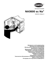
Figure 1 Sample flow valves
1 Sample flow valve 3 Sample flow valves for 2- or 4-channel analyzer
1
2 Sample flow valve for 1-channel analyzer
User interface and navigation
Keypad description
Refer to Figure 2 for the keypad description and navigation information.
Figure 2 Keypad description
1 Display 6 Diag: shows the Diag/Test Menu
2 RIGHT and LEFT arrows: change the measurement
screen and select options. Refer to Additional
measurement screens on page 7.
7 Cal: shows the Calibrate Menu
3 UP and DOWN arrows: change the channel shown
on the measurement screen, select options and
enter values.
8 Back: goes back to the previous screen
4 Home: shows the measurement screen 9 Menu: shows the main menu
5 Enter
1
A 2-channel analyzer only uses the bottom two valves.
English 5

Display description
Figure 3 shows the top half of the measurement screen. The top half of the measurement screen
shows the status of the analyzer and the sodium concentration for one channel. To change the
channel shown, push the UP or DOWN arrow. To show more than one channel, push the RIGHT
arrow.
The background color of the display changes to show the status of the analyzer. Refer to Table 1. To
show the active errors, warnings and reminders, push diag and select DIAGNOSTICS.
Figure 4 shows the bottom half of the measurement screen. The bottom half of the measurement
screen shows the measurement quality, service status and solution levels.
Figure 3 Measurement screen—top
1 Sodium concentration 6 Activity (shown during a measurement or calibration
process)
2 Channel name
2
7 Reminder (maintenance is due)
3 Analyzer name 8 SD card (shown when a SD card is inserted)
4 Home (measurement screen) 9 Relays (active relays are white squares)
5 Channel being measured 10 Parameter measured (Na
+
= sodium)
2
For example, "1-SAMPLE1" is "Channel 1-SAMPLE1". SAMPLE1 is the default name for
Channel 1. Channels that contain the symbol "~" are not measured (e.g., 4-~SAMPLE4).
6 English

Figure 4 Measurement screen—bottom
1 PROGNOSYS measurement quality indicator (refer
to PROGNOSYS indicator bars on page 7)
5 Reactivation solution level
2 Calibration information 6 Conditioning solution level
3 PROGNOSYS service indicator (refer to
PROGNOSYS indicator bars on page 7)
7 KCl electrolyte level
4 Calibration standard level
3
Table 1 Measurement screen—background colors
Color Definition
White The analyzer is in operation with no warnings, errors or reminders.
Yellow (warning or reminder) The analyzer is in operation with active warnings. Wrench symbol shows on the
display when the time for a maintenance task has passed.
Red (error) The analyzer is not in operation due to an error condition. A serious problem has
occurred.
PROGNOSYS indicator bars
The measurement quality indicator bar shows the overall measurement health of the analyzer (0 to
100%). The service indicator bar shows the number of days until a service task is necessary. Refer
to Table 2.
To see the parameters that have an effect on the indicator bars, push diag, then select
PROGNOSYS > MEASUREMENT INDICATOR or SERVICE INDICATOR.
Table 2 PROGNOSYS color descriptions
Color Measurement quality indicator bar Service indicator bar
Green The system is in good working condition and the health
percentage is more than 75%.
There are at least 30 days until the next
service task is necessary.
Yellow The system needs attention to prevent a failure in the
future. The health percentage is between 50 and 75%.
At least one service task is required in 1 to
30 days.
Red The system needs immediate attention. The health
percentage is below 50%.
One or more service tasks are required
within 1 day.
Additional measurement screens
From the measurement screen, additional measurement screens are available:
• Single channel analyzers:
3
Shows when the analyzer has the auto calibration option.
English 7

• Push the LEFT or RIGHT arrow to switch between the main display and a graphical display.
• Multi-channel analyzers:
• Push the UP or DOWN arrow to change the channel shown and see the last measurement for
the channel.
• Push the LEFT or RIGHT arrow to show more channels and a graphical display.
• In the graphical display, push the UP or DOWN arrow to show the graph for the previous or next
channel. Refer to Graphical display on page 8 for additional options.
Graphical display
The graphical display shows measurements for a maximum of four channels. The graph supplies
easy monitoring of trends and shows changes in the process.
1. From the main measurement screen, push the LEFT arrow to show the graphical display.
Note: Push the UP or DOWN key to show the graph for the previous or next channel in sequence.
2. Push home to change the graph settings.
3. Select an option.
Option Description
MEASUREMENT VALUE Sets the measurement value range on the graph for the selected channel. Select
between AUTO SCALE and MANUALLY SCALE. Enter the minimum and
maximum ppb value in the MANUALLY SCALE menu.
DATE & TIME RANGE Selects the date and time range to show on the graph: last day, last 48 hours, last
week or last month.
Configuration
Set the language
1. Push menu, then select SETUP SYSTEM > LANGUAGE.
2. Select the language that shows on the display and in the log files.
Remove channels from the measurement screen (2- or 4-channel
analyzers)
Remove the channels that are not measured (e.g., 4-~SAMPLE4) from the measurement screen.
Change the order that the channels show on the measurement screen as necessary.
1. Remove the channels that are not measured (e.g., 4-~SAMPLE4) from the measurement screen
as follows:
a. Push menu, then select SETUP SYSTEM > DISPLAY SETUP > ADJUST ORDER >
REMOVE MEASUREMENTS.
b. Select the channels that contain the symbol "~" (e.g., 4-~SAMPLE4), then push enter two
times.
Note: To add a channel to the measurement screen, select ADD MEASUREMENTS.
2. To change the order that the channels show on the measurement screen, select an option.
Option Description
SEE CURRENT ORDER Shows the order that channels show on the measurement screen.
REORDER LIST Sets the order that channels show on the measurement screen.
SEE DEFAULT ORDER Shows the default order that channels show on the measurement screen.
SET TO DEFAULT Sets the order that channels show on the measurement screen to the default
order.
8 English

Set the display brightness
1. Push menu, then select SETUP SYSTEM > DISPLAY SETUP > DISPLAY BACKLIGHT.
2. Enter a number from 1 to 9 (default: 5). Select a higher number to increase the brightness.
Set the maximum rinsing time
Set the maximum time interval the analyzer rinses the measurement cell at startup and immediately
after reactivation, grab sample measurement, calibration and prime reagents.
Rinsing removes the reactivation solution, grab sample or calibration standard from the
measurement cell. The analyzer rinses the measurement cell with the sample from the next channel
to be measured until the measurement is stable.
1. Push menu, then select SETUP SYSTEM > CONFIGURE ANALYZER > RINSE > MAX RINSE
TIME.
2. Enter the maximum rinse time (10 to 100 minutes). The recommended setting is 45 minutes
(default).
Set the sample target pH (analyzer without cationic pump)
Note: This task only applies to analyzers without the optional cationic pump. Refer to Product overview in the
installation manual to identify the cationic pump.
Before the measurement, the analyzer increases the pH of the sample to between 10.7 and 11.4 with
a conditioning solution to prevent ion interference. The analyzer automatically adjusts the quantity of
the conditioning solution that is added to the sample to keep the sample pH constant.
Set the target sample pH as follows:
1. Push menu, then select SETUP SYSTEM > CONFIGURE ANALYZER > MEASUREMENT > PH
TARGET.
2. Set the target pH (10.7 to 11.4). The recommended setting is pH 11.2 (default).
Set the sample target pH (analyzer with cationic pump)
Note: This task only applies to analyzers with the optional cationic pump. Refer to Product overview in the
installation manual to identify the cationic pump.
Before the measurement, the analyzer increases the pH of the sample to between 11.2 and 11.4 with
a conditioning solution to prevent ion interference. Set the ratio of the conditioning solution, which is
added as a gas, and the sample for each channel (Tgas/Twater). The Tgas/Twater ratio is based on
the pH of the unconditioned sample.
Item to collect: Calibrated pH sensor to put into the middle chamber of the measurement cell (or a
pH test strip)
Set the Tgas/Twater ratio for each channel as follows:
1. Identify the pH of the sample for each channel before it goes into the analyzer.
2. Push menu, then select SETUP SYSTEM > CONFIGURE ANALYZER > MEASUREMENT >
TGAS/TWATER.
3. Select the channels one at a time (e.g., TGAS/TWATER1 = Channel 1). Enter the applicable
Tgas/Twater value from Table 3 (default: 20%).
4. Push home.
5. Let the analyzer operate for 1 hour to stabilize.
6. Identify if the conditioned sample pH is between 11.2 and 11.4 as follows:
a. Remove the sodium electrode from the middle chamber of the measurement cell. Put the
sodium electrode in deionized water to keep the electrode wet.
b. Put a calibrated pH sensor in the middle chamber of the measurement cell.
English
9

c. For each channel, record the pH of the sample while the measurement status bar shows on
the display.
d. If the pH of a sample(s) is not between 11.2 and 11.4, set the Tgas/Twater setting for the
channel to a higher (or lower) percentage as necessary. Then, after 1 hour of operation, do
step c again.
e. If the pH of a sample(s) is not between 11.2 and 11.4 when the Tgas/Twater is set to the
maximum value, refer to "PH TOO LOW" in the troubleshooting table of the maintenance
manual to identify the problem.
7. When the conditioned sample pH of each channel is between 11.2 and 11.4, install the sodium
electrode back in the middle chamber of the measurement cell.
Table 3 Tgas/Twater ratio
pH of sample Tgas/Twater ratio pH of sample Tgas/Twater ratio
2 200% 2.9 30%
2.3 80% 3.5 21%
2.6 50% 4.0 18%
Set the measurement logging interval (1-channel analyzers)
Set the measurement logging interval. Measurements are saved to the data log at the measurement
logging interval. In addition, the relays and analog outputs are updated at the measurement logging
interval.
Note: This procedure applies to analyzers that can only be plumbed to one sample source. For analyzers that can
be plumbed to more than one sample source, go to Set the measurement logging interval (2- or 4-channel
analyzers) on page 11.
1. Push menu, then select SETUP SYSTEM > CONFIGURE ANALYZER > MEASUREMENT >
SET MEASURE CYCLE > CYCLE TIME.
2. Enter the measurement logging interval (default: 10 minutes).
Note: The analyzer measures the sample continuously during the CYCLE TIME selected. The measurement
shows on the display. At the end of the CYCLE TIME, the analyzer saves the average measurement for the last
minute to the data log. In addition, the analyzer updates the relays and analog outputs so they represent the
saved measurement.
10
English

Set the measurement logging interval (2- or 4-channel analyzers)
Set the measurement logging interval. Measurements are saved to the data log at the measurement
logging interval. In addition, the relays and analog outputs are updated at the measurement logging
interval.
1. Push menu, then select SETUP SYSTEM > CONFIGURE ANALYZER > MEASUREMENT >
SET MEASURE CYCLE.
2. Select and configure each option. Select SEARCH STABILITY first.
Option Description
SEARCH
STABILITY
Between channel measurements, the analyzer rinses the measurement cell with sample
from the next channel to be measured for a set time interval (or until the measurement is
stable).
NO (default)—Sets search stability to off. The analyzer rinses the measurement cell for a set
time interval. As a result, the measurement logging interval is constant.
When SEARCH STABILITY is set to NO, the settings to configure are CYCLE TIME and ON
LINE MEASURE time.
Measurement logging interval = CYCLE TIME
CYCLE TIME = ON LINE MEASURE time + Rinsing time (set value)
YES—Sets search stability to on. The analyzer rinses the measurement cell only until the
measurement is stable, which minimizes the rinsing time. As a result, the measurement
logging interval is variable.
When SEARCH STABILITY is set to YES, the settings to configure are MAX CYCLE TIME
(maximum measurement logging interval) and ON LINE MEASURE time.
Measurement logging interval = ON LINE MEASURE time + Rinsing time (variable)
ON LINE
MEASURE
Sets the amount of time the analyzer measures the channel (1 to 119 minutes, default:
10 minutes).
Note: The analyzer measures the channel continuously during the ON LINE MEASURE
time. The measurement shows on the display. At the end of the ON LINE MEASURE time,
the analyzer saves the average measurement for the last minute to the data log. In addition,
the analyzer updates the relays and analog outputs so they represent the saved
measurement.
MAX CYCLE
TIME
Note: The MAX CYCLE TIME option only shows when SEARCH STABILITY is set to YES.
Sets the maximum measurement logging interval (11 to 120 minutes, default: 45 minutes).
Sets the maximum rinsing time. For example, if the MAX CYCLE TIME setting is 45 minutes
and the ON LINE MEASURE setting is 10 minutes, the maximum rinsing time is 35 minutes.
CYCLE TIME Note: The CYCLE TIME option only shows when SEARCH STABILITY is set to NO.
Sets the measurement logging interval (11 to 120 minutes, default: 45 minutes). Sets the
rinsing time. For example, if the CYCLE TIME setting is 20 minutes and the ON LINE
MEASURE setting is 10 minutes, the rinsing time is 10 minutes.
English 11

Set the reactivation schedule
With time, the sensitivity of the sodium electrode decreases because of the very low levels of sodium
in the sample water. Auto reactivation adds a small quantity of reactivation solution to the
measurement cell at regular intervals (e.g., 24 hours) to increase the sensitivity of the sodium
electrode. Auto reactivation increases the accuracy of the analyzer measurements.
1. Push menu, then select SETUP SYSTEM > CONFIGURE ANALYZER > REACTIVATION > SET
AUTO REACTIVATION.
2. Select an option.
Option Description
ENABLE AUTO
REACTIVATION
YES (default)—Sets auto reactivation to on. NO—Sets auto reactivation to off.
Note: If reactivation is off, a reactivation is only done before a calibration.
TIME BASE DAYS—Sets auto reactivation to occur on selected days at a selected time (e.g.,
daily at 9:00 am). HOURS (default)—Sets a time interval between reactivations
(e.g., 24 hours).
WEEK DAY Note: The WEEK DAY option only shows when TIME BASE is set to DAYS.
Sets the days of the week that a reactivation is done. All of the days of the week are
selected by default. The default setting is recommended.
TIME Note: The TIME option only shows when TIME BASE is set to DAYS.
Sets the time a reactivation is done in 24-hour format (default: 12:00).
SET INTERVAL Note: The SET INTERVAL option only shows when TIME BASE is set to HOURS.
Sets the time interval between reactivations (2 to 168 hours). The recommended
time interval is 24 hours (default).
Set the measurement units
Set the measurement units that show on the measurement screen.
1. Push menu, then select SETUP SYSTEM > CONFIGURE ANALYZER > MEAS UNITS.
2. Select the measurement units (ppm, ppb, mg/L or µg/L).
Set the signal average
Set the number of saved measurements the analyzer uses to calculate an average measurement
(1–5). At the end of the measurement cycle, the analyzer saves the average measurement to the
data log. In addition, the analyzer updates the relays and analog outputs so they represent the saved
measurement. The signal average setting decreases variability in measurements.
1. Push menu, then select SETUP SYSTEM > CONFIGURE ANALYZER > SIGNAL AVERAGE.
2. Push the UP or DOWN arrow key to set the value. The default is 1 (no signal average used).
Change the analyzer or channel names
1. Push menu, then select SETUP SYSTEM > CONFIGURE ANALYZER.
2. Select an option.
Option Description
EDIT ANALYZER
NAME
Changes the name of the analyzer. Enter a unique name, such as the analyzer
location (16 characters maximum). The analyzer name shows on the measurement
screen and the data logs.
EDIT CHANNEL
NAME
Changes the name of the selected channel. Enter a unique name, such as the
source of the sample water (10 characters maximum). The channel name(s) shows
on the measurement screen and the data logs.
12 English

Start or stop measurements on a channel (2- or 4-channel analyzers)
1. Push menu, then select SETUP SYSTEM > CONFIGURE ANALYZER > CONFIGURE
SEQUENCER > ACTIVATE CHANNELS.
2. Select a channel to start measurements. Unselect a channel to stop measurements. Push the
LEFT arrow to select or unselect a checkbox.
Change the channel measurement order (2- or 4-channel analyzers)
To change the order that the channels are measured, do the steps that follow:
1. Push menu, then select SETUP SYSTEM > CONFIGURE ANALYZER > CONFIGURE
SEQUENCER > SEQUENCE CHANNELS.
2. Push the UP and DOWN arrows to select a row.
Note: S1 is the first channel measured, followed by S2, S3 and S4.
3. Push the LEFT or RIGHT arrow to select a channel.
Note: Do not select channels that contain the symbol "~" (e.g., 4-~SAMPLE4). Channels that contain the
symbol "~" are not measured.
Set the date and time
Set the date and time format and the date and time that show on the measurement screen and in the
log files.
1. Push menu, then select SETUP SYSTEM > CONFIGURE ANALYZER > SET DATE/TIME.
2. Select an option.
Option Description
DATE FORMAT Sets the date format (YYYY= year, MM=month and DD=day) and time format (12-hour or
24-hour). Default: YYYY-MM-DD 24 hours.
DATE/TIME Sets the date and time. Use the arrow buttons to enter the date and time.
Configure the 4-20 mA analog outputs
If an analog output(s) in the analyzer is connected to an external device, select the channel
represented at the analog output and the measurement range.
1. Enable an analog output as follows:
a. Push menu, then select SETUP SYSTEM > CONFIGURE ANALYZER > SETUP OUTPUTS
> 4-20 mA SETUP > [select an output].
b. Select SELECT SOURCE > [analyzer name].
2. Select an option.
Note: Select SET PARAMETER first, then SET FUNCTION and then ACTIVATION.
Option Description
ACTIVATION The ACTIVATION options change based on the SET FUNCTION setting. Refer to the
tables that follow to configure the analog output.
SELECT SOURCE NONE (default)—Sets the analog output to disabled. [analyzer name]—Sets the analog
output to enabled.
SET PARAMETER Sets the channel represented at the analog output.
Note: Do not select a channel that contains the symbol "~" (e.g., 4-~SAMPLE4).
Channels that contain the symbol "~" are not measured.
English 13

Option Description
SET FUNCTION Sets the function of the analog output. Refer to the tables that follow for more
information. LINEAR CONTROL (default)—The analog output is linearly dependent on
the measurement value. PID CONTROL—The analog output operates as a PID
(Proportional, Integral, Derivative) controller. LOGARITHMIC—The analog output is
represented logarithmically within the measurement range. BILINEAR—The analog
output is represented as two linear segments within the measurement range.
SET TRANSFER Sets the value of the analog output when an error occurs if the ERROR HOLD MODE
setting is set to TRANSFER OUTPUTS (0 to 25 mA, default: 4 mA). Refer to Set the
error hold mode on page 21.
SET FILTER Sets the amount of time for analog output averaging (0 to 999 seconds, default:
0 seconds). For example, if the value is set to 30 seconds, the value of the analog
outputs is updated every 30 seconds and the value is the average of the analog output
values during the previous 30 seconds.
SCALE 0mA/4mA Sets the analog output value range to 0–20 mA or 4–20 mA (default).
• LINEAR CONTROL function
Option Description
SET LOW VALUE Sets the low measurement value that is represented as 0 or 4 mA at the analog output.
SET HIGH VALUE Sets the high measurement value that is represented as 20 mA at the analog output.
• PID CONTROL function
Option Description
SET MODE AUTO—The analog value (mA) is automatically controlled by the algorithm when the
analyzer uses proportional, integral and derivative inputs. MANUAL—The analog value
(mA) is controlled by the user. To change the value manually, change the % value in
MANUAL OUTPUT.
PHASE DIRECT—The analog value increases as the measurement value increases. REVERSE—
The analog value increases as the measurement value decreases.
SET SETPOINT Sets a measurement value as the setpoint value.
PROP BAND Sets a value for the difference between the measured value and the setpoint value.
INTEGRAL Sets the time interval from the reagent injection point to the contact with the measuring
device.
DERIVATIVE Sets a value that adjusts for vacillation of the process. The majority of applications can be
controlled without the use of the derivative setting.
TRANSIT TIME Sets the value to stop the PID control for a selected period of time when the sample moves
from the sample valve to the measurement electrode.
• LOGARITHMIC function
Option Description
SET 50% VALUE Sets the value corresponding to 50% of the process variable range.
SET HIGH VALUE Sets the high endpoint (upper value) of the process variable range.
14 English

• BILINEAR function
Option Description
SET LOW VALUE Sets the low endpoint (lower value) of the process variable range.
SET HIGH VALUE Sets the high endpoint (upper value) of the process variable range.
SET KNEE POINT VALUE Sets the value at which the process variable range divides into another linear
segment.
SET KNEE POINT CURRENT Sets the value of the current at the knee point value.
Configure the relays
If a relay(s) in the analyzer is connected to an external device, select the triggers that set the relay to
on (active). The relay status shows at the top-right corner of the measurement screen. Refer to
Figure 3 on page 6.
Note: The Normally Open (NO) and Common (COM) relay contacts are connected when the relay is on. The
Normally Closed (NC) and Common relay contacts are connected when an the relay is off.
1. Enable a relay as follows:
a. Push menu, then select SETUP SYSTEM > CONFIGURE ANALYZER > SETUP OUTPUTS
> RELAY SETUP > [select a relay].
b. Select SELECT SOURCE > [analyzer name].
2. Select an option.
Note: Select SET PARAMETER first, then SET FUNCTION and then ACTIVATION.
Option Description
ACTIVATION The ACTIVATION options change based on the SET FUNCTION setting. Refer to the
tables that follow to configure the relay.
SELECT SOURCE NONE—Sets the relay to disabled. [analyzer name]—Sets the relay to enabled.
SET PARAMETER Sets the channel represented at the relay.
Note: Do not select a channel that contains the symbol "~" (e.g., 4-~SAMPLE4).
Channels that contain the symbol "~" are not measured.
SET FUNCTION ALARM (default)—Sets the relay to on when the measurement value is more than the
high alarm value or less than the low alarm value. FEEDER CONTROL—Sets the relay
to on if a measurement value is more (or less) than the setpoint value. EVENT
CONTROL—The relay toggles if a process value reaches an upper or lower limit.
SCHEDULER—Sets the relay to on at selected times regardless of the measurement
value. WARNING—Sets the relay to on when there is a warning or error condition.
PROCESS EVENT—Sets the relay to on when the analyzer does a selected operation.
SET TRANSFER Sets the relay to active (on) or inactive (off) when an error occurs if the ERROR HOLD
MODE setting is set to TRANSFER OUTPUTS. The default setting is INACTIVE (off).
Refer to Set the error hold mode on page 21.
FAIL SAFE YES—Sets the normal condition for the relays to be active (on). NO—Sets the normal
condition for the relays to be inactive (off).
• ALARM function (refer to Figure 5)
Option Description
LOW ALARM Sets the value where the relay is set to on in response to decreasing measured value.
For example, if the low alarm is set for 1.0 and the measured value drops to 0.9, the
relay activates.
HIGH ALARM Sets the value where the relay is set to on in response to increasing measured value.
For example, if the high alarm is set for 1.0 and the measured value increases to 1.1,
the relay activates.
English 15

Option Description
LOW DEADBAND Sets the range where the relay stays on after the measured value increases above the
low alarm value. For example, if the low alarm is set for 1.0 and the low deadband is set
for 0.5, the relay stays on between 1.0 and 1.5.
HIGH DEADBAND Sets the range where the relay stays on after the measured value decreases below the
high alarm value. For example, if the high alarm is set for 4.0 and the high deadband is
set for 0.5, the relay stays on between 3.5 and 4.0.
OFF DELAY Sets a delay time for the relay to be set to off.
ON DELAY Sets a delay time for the relay to be set to on.
Figure 5 Alarm function
1 High alarm 4 Low alarm 7 Time (x-axis)
2 High deadband 5 ON delay 8 Source (y-axis)
3 Low deadband 6 OFF delay
• FEEDER CONTROL function (refer to Figure 6 and Figure 7)
Option Description
PHASE HIGH—Sets the relay to on when the measured value is more than the setpoint value.
LOW—Sets the relay to on when the measured value is less than the setpoint value.
SET SETPOINT Sets a measurement value as the setpoint value.
DEADBAND Sets the deadband value for the relay. If PHASE is set to LOW, the relay stays on until
the measurement value increases to more than the setpoint value plus the deadband
value. If PHASE is set to HIGH, the relay stays on until the measurement value
decreases to less than the setpoint value minus the deadband value.
OVERFEED TIMER Sets a time limit for how long the relay can stay on. Once an overfeed alarm is present,
it must be manually reset. Refer to Reset the overfeed timer for relays on page 21.
16 English

Option Description
OFF DELAY Sets a delay time before the relay is set to off.
ON DELAY Sets a delay time before the relay is set to on.
Figure 6 Feeder control function
1 Deadband (Phase = Low) 4 OFF delay (phase set high) 7 ON delay (phase set high)
2 Deadband (Phase = High) 5 ON delay (phase set low) 8 OFF delay (phase set low)
3 Setpoint 6 Time (x-axis) 9 Source (y-axis)
English 17

Figure 7 Feeder control function (phase low, overfeed timer)
1 Deadband 4 Time (x-axis) 7 Source (y-axis)
2 Setpoint 5 ON delay
3 Overfeed timer 6 OFF delay
• EVENT CONTROL function (refer to Figure 8 and Figure 9)
Option Description
SET SETPOINT Sets a measurement value where the relay is set to on.
DEADBAND Sets a hysteresis so the relay will not swing unregulated when the measurement value
converges to the setpoint.
OnMax TIMER Sets the maximum time the relay can stay on independent from the measured value.
OffMax TIMER Sets the maximum time the relay can stay off independent from the measured value.
OnMin TIMER Sets the minimum time the relay can stay on independent from the measured value.
OffMin TIMER Sets the minimum time the relay can stay off independent from the measured value.
18 English

Figure 8 Event control function (no delay)
1 Source (y-axis) 3 Setpoint 5 OnMax-time
2 Deadband 4 Time (x-axis) 6 OffMax-time
Figure 9 Event control function (OnMin timer, OffMin timer)
1 Deadband 3 Time (x-axis) 5 OnMin timer
2 Setpoint 4 OffMin timer 6 Source (y-axis)
English 19

• SCHEDULER function (refer to Figure 10)
Option Description
HOLD OUTPUTS Holds or transfers outputs for the selected channels.
RUN DAYS Sets the days that the relay operates.
START TIME Sets the start time.
INTERVAL Sets the time between activation cycles (0 to 999 seconds, default: 0).
DURATION Sets the period of time the relay is energized (0 to 999 seconds, default: 0).
OFF DELAY Sets the time for additional hold/output time after the relay has been turned off (0 to
999 seconds, default: 0).
Figure 10 Scheduler function
1 Duration 3 Interval
2 OFF delay 4 Time (x-axis)
• WARNING function
Option Description
WARNING LEVEL Sets the relay to on when the selected warning(s) occurs. Push the LEFT arrow to select
or unselect a checkbox.
• PROCESS EVENT function
Option Description
SELECT
EVENTS
Sets the relay to on when the selected process event(s) occurs. Push the LEFT arrow to select
or unselect a checkbox.
MEASURING 1, 2, 3 or 4—Sets the relay to on during the measurement cycle of Channel 1, 2,
3 or 4.
CALIBRATE—Sets the relay to on during calibration.
SHUTDOWN—Sets the relay to on when in shutdown mode.
STARTUP—Sets the relay to on during the startup cycle.
GRAB SAMPLE—Sets the relay to on during grab sample measurement.
MARK END OF MEASURE—Sets the relay to on for 1 second at the end of each
measurement cycle.
20 English

Reset the overfeed timer for relays
The overfeed timer setting for the relays prevents a condition that keeps the measurement value
higher than the setpoint or deadband setting (e.g., damaged electrode or a process upset) from
keeping a relay switched on continuously. The overfeed timer limits how long the relays and their
connected control element stay on independent of the conditions.
When the select time interval for the overfeed timer expires, the relay status flashes on the top-right
corner of the measurement screen until the overfeed timer is reset. Push diag, then select
OVERFEED RESET to reset the overfeed timer.
Set the error hold mode
If an analog output or relay in the analyzer is connected to an external device, select the error hold
mode.
1. Push menu, then select SETUP SYSTEM > CONFIGURE ANALYZER > SETUP OUTPUTS >
ERROR HOLD MODE.
2. Select an option.
Option Description
HOLD OUTPUTS
(default)
Holds the relays and analog outputs at the last known value when an error occurs or
measurements are stopped (e.g., calibration, rinse, reactivation or grab sample
measurement).
TRANSFER
OUTPUTS
Sets the relays and analog outputs to the transfer value set in the analog output and
relay settings when an error occurs or measurements are stopped (e.g., calibration,
rinse, reactivation or grab sample measurement).
Set the security settings
Enable passcode protection as necessary. Select the menu options that are passcode protected.
Note: Passcode protection is disabled by default.
1. Push menu, then select SETUP SYSTEM > CONFIGURE ANALYZER > SECURITY SETUP.
2. Select an option.
Option Description
SET PASS CODE DISABLED (default)—Sets the passcode protection to off. ENABLED—Sets the
passcode protection to on. Enter the default passcode (HACH55).
EDIT PASS CODE Changes the passcode (6 characters maximum).
PROTECT FEATURES Selects the menu options that are passcode protected. The menu options that are
selected are passcode protected. Push the LEFT arrow to select or unselect a
checkbox.
Adjust the water level of the overflow vessel
Note: Only do this task if the analyzer has a calibration bottle. Refer to Product overview in the installation manual
to identify the calibration bottle.
The water level of the overflow vessel is important for accurate auto calibration. Before an auto
calibration is done, adjust the water level so that the water is between the top mark (+) and the
bottom mark (–). Make sure that the analyzer is level from front to back and side to side.
1. Wait until the overflow vessel is full of water.
2. If the water is higher than the top mark (+) or lower than the bottom mark (–) on the overflow
vessel, do the steps that follow:
a. Push menu, then select SETUP SYSTEM > CONFIGURE ANALYZER > OVERFLOW
COMPENSATION.
English
21
/