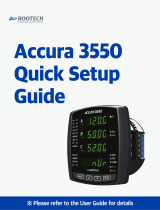
Fluke Norma 6000 Series Portable Power Analyzers User manual

Type
User manual
NORMA 6003/NORMA 6003+/
NORMA 6004/NORMA 6004+
Power Analyzers
Users Manual
July 2019 Rev. 2, 3/20 (English)
© 2019-2020 Fluke Corporation. All rights reserved. Specifications are subject to change without notice.
All product names are trademarks of their respective companies.
LIMITED WARRANTY AND LIMITATION OF LIABILITY
Each Fluke product is warranted to be free from defects in material and workmanship under normal use and
service. The warranty period is two years and begins on the date of shipment. Parts, product repairs, and services
are warranted for 90 days. This warranty extends only to the original buyer or end-user customer of a Fluke
authorized reseller, and does not apply to fuses, disposable batteries, or to any product which, in Fluke's opinion,
has been misused, altered, neglected, contaminated, or damaged by accident or abnormal conditions of operation
or handling. Fluke warrants that software will operate substantially in accordance with its functional specifications
for 90 days and that it has been properly recorded on non-defective media. Fluke does not warrant that software
will be error free or operate without interruption.
Fluke authorized resellers shall extend this warranty on new and unused products to end-user customers only but
have no authority to extend a greater or different warranty on behalf of Fluke. Warranty support is available only if
product is purchased through a Fluke authorized sales outlet or Buyer has paid the applicable international price.
Fluke reserves the right to invoice Buyer for importation costs of repair/replacement parts when product purchased
in one country is submitted for repair in another country.
Fluke's warranty obligation is limited, at Fluke's option, to refund of the purchase price, free of charge repair, or
replacement of a defective product which is returned to a Fluke authorized service center within the warranty
period.
To obtain warranty service, contact your nearest Fluke authorized service center to obtain return authorization
information, then send the product to that service center, with a description of the difficulty, postage and insurance
prepaid (FOB Destination). Fluke assumes no risk for damage in transit. Following warranty repair, the product will
be returned to Buyer, transportation prepaid (FOB Destination). If Fluke determines that failure was caused by
neglect, misuse, contamination, alteration, accident, or abnormal condition of operation or handling, including
overvoltage failures caused by use outside the product’s specified rating, or normal wear and tear of mechanical
components, Fluke will provide an estimate of repair costs and obtain authorization before commencing the work.
Following repair, the product will be returned to the Buyer transportation prepaid and the Buyer will be billed for the
repair and return transportation charges (FOB Shipping Point).
THIS WARRANTY IS BUYER'S SOLE AND EXCLUSIVE REMEDY AND IS IN LIEU OF ALL OTHER
WARRANTIES, EXPRESS OR IMPLIED, INCLUDING BUT NOT LIMITED TO ANY IMPLIED WARRANTY OF
MERCHANTABILITY OR FITNESS FOR A PARTICULAR PURPOSE. FLUKE SHALL NOT BE LIABLE FOR ANY
SPECIAL, INDIRECT, INCIDENTAL OR CONSEQUENTIAL DAMAGES OR LOSSES, INCLUDING LOSS OF
DATA, ARISING FROM ANY CAUSE OR THEORY.
Since some countries or states do not allow limitation of the term of an implied warranty, or exclusion or limitation
of incidental or consequential damages, the limitations and exclusions of this warranty may not apply to every
buyer. If any provision of this Warranty is held invalid or unenforceable by a court or other decision-maker of
competent jurisdiction, such holding will not affect the validity or enforceability of any other provision.
11/99
Fluke Corporation
P.O. Box 9090
Everett, WA 98206-9090
U.S.A.
Fluke Europe B.V.
P.O. Box 1186
5602 BD Eindhoven
The Netherlands
ООО «Флюк СИАЙЭС»
125167, г. Москва,
Ленинградский проспект дом 37,
корпус 9, подъезд 4, 1 этаж
LIMITED WARRANTY AND LIMITATION OF LIABILITY
i
Table of Contents
Title Page
Introduction ........................................................................................................... 1
How to Contact Fluke............................................................................................ 2
Safety Information................................................................................................. 2
Preparation ........................................................................................................... 3
Standard Equipment........................................................................................ 3
Setup ............................................................................................................... 5
Connect to the Power Supply .......................................................................... 6
Charge the Battery........................................................................................... 7
The Product .......................................................................................................... 8
Control Panel................................................................................................... 9
Display Screen................................................................................................. 12
Status bar ................................................................................................... 13
Main Display Area ...................................................................................... 13
Soft Keys .................................................................................................... 13
Interface Panel................................................................................................. 14
Operation .............................................................................................................. 15
Global Configuration........................................................................................ 15
Set Range................................................................................................... 15
Motor Speed / Torque Channel Configuration............................................ 19
Set the Wiring Selection ............................................................................. 20
Wiring Group .............................................................................................. 24
Set Sync Source and Update Rate............................................................. 26
Zero ............................................................................................................ 27
Define Calculation Formula ........................................................................ 28
Meter................................................................................................................ 30
Preview....................................................................................................... 31
User Item View ........................................................................................... 32
Integration................................................................................................... 34
Harmonic ......................................................................................................... 35
Change View Mode .................................................................................... 36
Select the Harmonics to Display................................................................. 36
Harmonic Bar.............................................................................................. 37
FFT............................................................................................................. 38
Linear and Logarithmic Axis ....................................................................... 39
Phasor ............................................................................................................. 40
Select the Phasor Data to Display.............................................................. 42
Select Circuit Type ..................................................................................... 42
Zoom Phasor.............................................................................................. 42
Scope............................................................................................................... 43
TiS55+/TiS75+
Users Manual
ii
Select the Waveform to Display.................................................................. 46
Trigger Setup .............................................................................................. 46
Measure with The Cursor............................................................................ 48
Zoom and Shift the Waveform .................................................................... 49
Trend................................................................................................................ 50
Select the Trend to Display......................................................................... 52
Set Measurement Period ............................................................................ 53
Zoom and Shift the Trend ........................................................................... 54
Data Management............................................................................................ 55
Save Data ................................................................................................... 55
Logger......................................................................................................... 55
Auto Logger ................................................................................................ 56
Logger Interval............................................................................................ 56
Dual-Unit Interconnection................................................................................. 59
Dual-Unit Interconnection Measurement .................................................... 60
Connect the Computer..................................................................................... 61
System Settings .................................................................................................... 62
General Settings .............................................................................................. 63
Language.................................................................................................... 63
Set Time and Date ...................................................................................... 63
Auto-Off....................................................................................................... 63
Memory....................................................................................................... 64
Set Communication Parameters ...................................................................... 64
Remote............................................................................................................. 65
Instrument Maintenance................................................................................... 65
Calibration........................................................................................................ 66
Maintenance.......................................................................................................... 66
Cleaning........................................................................................................... 66
Change the Battery .......................................................................................... 66
Change the Fuse.............................................................................................. 68
Firmware Upgrade ........................................................................................... 69
Specifications ........................................................................................................ 70
General Specifications ..................................................................................... 70
Electrical Specifications ................................................................................... 71
Voltage........................................................................................................ 71
Accuracy ..................................................................................................... 71
Current........................................................................................................ 72
Accuracy ..................................................................................................... 72
Motor (NORMA 6003+NORMA 6004+)................................................... 72
Frequency Domain Measurement............................................................... 73
Appendix A............................................................................................................ 75
Measurement Calculation Method ................................................................... 75
How to Make More Accurate Measurements ................................................... 80
Measurement Error Caused by the Channel Resistance............................ 80
Effects of Leakage Capacitance ................................................................. 81
Broadband Measurement ........................................................................... 82
1
Introduction
The Fluke NORMA 6003/NORMA 6003+/NORMA 6004/NORMA 6004+ Power Analyzers (the Product
or Analyzer) are portable, precision wideband power analyzers. Use the product with the Fluke current
clamp 80i-2010s and High Voltage Differential Probe U1500s for a broad range of electrical loads
including those with electronic switching (inverter type).
The Product has these benefits:
Up to 4 voltage and 4 current channels (NORMA 6003+, NORMA 6004+).
Motor Speed and Torque measurements (NORMA 6003+, NORMA 6004+)
0.1 % accuracy, 500 kHz bandwidth, 200 kHz sample rate.
The channels are isolated (basic insulation) with the measurement category of CAT III 1000V /
CAT IV 600V.
Flexible configurations according to the measuring requirements, synchronize 2 Analyzers to
configure 6 to 8 channels.
9.6 cm thickness makes it easy to use in tight spaces.
5000 mAh Li-ion battery for 10 hours continuous operation with one single charge.
CAT rating: CAT III 1000 V, CAT IV 600 V
100 ms to 1 s configurable update rate, 32 GB storage available for continuous logging.
Main functions: Meter, Scope, Harmonic, Phasor and Trend.
USB and RS485 interface with open communication protocol support user defined system
integration and software.
Simplified UI for better operation experience, suitable for in-field application.
PC software (Fluke Power Analyzer Software) for online measuring, data downloading, and
analysis.
NORMA 6003/NORMA 6003+/NORMA 6004/NORMA 6004+
Users Manual
2
How to Contact Fluke
To contact Fluke, call one of the following telephone numbers:
Technical Support USA: 1-800-44-FLUKE (1-800-443-5853)
Calibration/Repair USA: 1-888-99-FLUKE (1-888-993-5853)
Canada: 1-800-36-FLUKE (1-800-363-5853)
Europe: +31 402-675-200
Japan: +81-3-6714-3114
Singapore: +65-6799-5566
China: +86-400-921-0835
Brazil: +55-11-3530-8901
Anywhere in the world: +1-425-446-5500
Or, visit Fluke's website at www.fluke.com
.
To register your product, view, print, or download the latest manual or manual supplement, visit
cn.fluke.com
(Chinese) or www.fluke.com (English).
Safety Information
General Safety Information is located in the printed Getting Started Manual that ships with the Product
and online at www.fluke.com
or cn.fluke.com. More specific safety information is listed where
applicable.
Power Analyzers
Preparation
3
Preparation
Standard Equipment
The Product is shipped in a container designed to prevent damage during shipment. Inspect the
Product carefully for damage, and immediately report any damage to the shipper.
Figure 1 and Table 1 list the equipment and accessories included with this Product. For specific
information on each part and more accessories, see the printed Getting Started Manual that ships with
the Product and online at www.fluke.com.
Unpack the Product and check for all the standard equipment listed in Table 1 and check the shipping
order for additional items ordered. Report any shortage to the place of purchase or to the nearest
Technical Service Center.
If it is necessary to reship the Product, use the original container. If it is not available, you can order
new packaging from Fluke by identifying the Product model and serial number.
Figure 1. Standard Equipment
1 2 3
4
5
6
7
8
9
NORMA 6003/NORMA 6003+/NORMA 6004/NORMA 6004+
Users Manual
4
Table 1. Standard Equipment
Item Description
Quantity
NORMA
6004/6004+
NORMA
6003/6003+
Main unit, including battery BP291: 3894688 1 1
Power Supply Adapter (18V DC, CAT IV 600V
Adapter)
11
Power line cord (for China): 4894155
Power line cord (for international): 4894137
Mains Adapter set (for international): 4894143
11
D
Test lead set
4-channel model:
Test leads, 1.5 m, (4) red, (4) black, (4) blue
Test leads, 0.18 m, (8) blue
Alligator clips, (4) red, (4) black, (4) blue
3-channel model:
Test leads, 1.5 m, (3) red, (3) black, (3) blue
Test leads, 0.18 m, (6) blue
Alligator clips, (3) red, (3) black, (3) blue
11
E USB (mini B) cable 1 1
F RS-485/synchrony adapter (3.81 mm, black, 3 pin) 1 1
G Speed / torque adapter (3.81 mm, black, 6 pin) None/1 None/1
H
USB Flash Drive for PC SW, (contains User
Manual)
11
Not Shown
Getting Started Manual 1 1
Product Warranty and Certification (China only) 1 1
Calibration Report 1 1
QC certificate (for China only) 1 1
Power Analyzers
Preparation
5
Setup
The Analyzer is portable and equipped with a tilt stand that allows the Analyzer to be placed on a flat
surface for users to view the screen from a certain angle, as shown in Figure 2.
Note
Do not use the tilt stand to carry the Product.
Figure 2. Use the tilt stand
Install the supplied hand strap on the left side of the Product. Adjust the handstrap, as shown in
Figure 3.
Figure 3. Install the hand strap
You can hold the Product in one hand when working and use the hand strap to carry the Product when
the Product is not in use.
NORMA 6003/NORMA 6003+/NORMA 6004/NORMA 6004+
Users Manual
6
Connect to the Power Supply
Connect the Analyzer to a standard AC power supply according to Figure 4 and turn on the Analyzer:
1. Connect the connector end of the power cord to the power adapter/charger and insert the plug into
a standard wall outlet.
2. Open the protective cover and insert the power adapter/charger plug into the power jack on the
Analyzer.
3. Push O on the front panel to turn on the Analyzer.
Figure 4. Connect to the Power Supply
 Warning
To prevent electric shock, connect the Product to a standard outlet using a factory-
supplied power cord.
Power Analyzers
Preparation
7
Charge the Battery
Before you use the Product for the first time, charge the battery.
When powered by a battery, the battery symbol at the top of the screen indicates the condition of the
battery. indicates low battery power, charge the battery immediately.
To charge the battery and power the instrument, connect the power adapter as shown in Figure 5. To
increase the battery charging speed turn off the Analyzer.
Figure 5. Battery Charging
 Caution
To prevent overheating of the battery during charging, do not charge in extremely hot
or cold environments. If the battery is charged under extreme temperatures, the battery
capacity may be reduced. Refer to charging temperature specifications.
Note
Charge the Product for a two-hour minimum at three-month intervals for maximum battery life.
When not in use, the full charged battery will self-discharge in approximately six months.
Batteries stored for long periods will need two to ten charging cycles for full capacity.
NORMA 6003/NORMA 6003+/NORMA 6004/NORMA 6004+
Users Manual
8
The Product
This section describes the operation panel of the Product and the location and function of the display.
Please read this section carefully before operating the Product. This manual is applicable to many
models. Because models have different features and accessories, not all of the information in the
manual may apply to your Product.
Table 2 is a list of functional comparison of different models.
Table 2. Product Features Table
Feature NORMA 6003 NORMA 6003+ NORMA 6004 NORMA 6004+
Number of channels for
voltage / current
3/3 3/3 4/4 4/4
Motor speed / torque
measurement
-
@
-
@
Basic accuracy 0.1%
Bandwidth 500kHz (High voltage/current range)
Sample rate 200 kHz
Channel-to-channel
isolation
@
Meter (V / I / P / η etc.)
@
Waveform
@
Trend
@
Harmonic
@
Phasor
@
CAT rating CAT III 1000V, CAT IV 600V
Ingress protection IP50
Color screen 5.7" backlight, 4:3
Lithium battery 10.8 V/5000 mAh, 54 Wh
Charging indication when
power off
Charging: power indicator is orange
Fully charged: power indicator is green
Charger Charging/powering
PC software
@
USB (device) – Mini B
@
485 / sync interface
@
(up to 921,600 bps)
Low battery indicator
@
Power Analyzers
The Product
9
Control Panel
Figure 6 and Table 3 list the features and function of each component on the control panel.
Figure 6. Control Panel
Table 3. Components on the Control Panel
Item Description
Power button
The power button also indicates the AC power connection. If the
indicator light is lit, when the Product is off, the AC power is
connected. The button is orange when the battery is being charged
and green when the battery is fully charged.
Push to turn on/off the Analyzer.
Push and hold for 15 seconds to force the Analyzer to shut down.
Screen
See Display Screen.
1
2
3
4
5
678
NORMA 6003/NORMA 6003+/NORMA 6004/NORMA 6004+
Users Manual
10
Function keys
The 1 to 5 function keys correspond to the soft keys from top
to bottom on the right next to the screen, the corresponding function
keys are equivalent to the soft keys. The label of the soft key varies
depending on the function and interface.
D
Back key
Push J to exit the current screen and return to the previous
screen or the previous menu
Select key
When a function on the screen is selected (highlighted in yellow),
push S to select or enter the function.
Arrow keys (up, down, left, and right)
Push the keys to go through all selectable functions on the screen
and select one of them, the currently selected function is highlighted
in yellow.
Table 3. Components on the Control Panel (cont.)
Item Description
Power Analyzers
The Product
11
Interface buttons
E
Hold/Run
Push h, the Product freezes the reading on the screen and the
screen will not refresh until you push h again.
Although the screen is frozen, the Product continues to measure.
Save/Logger
Short push: Save the current data or settings of the Analyzer.
Push and hold for 2 seconds: Enter the logger mode to
continuously log the measurements of the current screen (for
Meter mode only).
See Data Management for details.
Meter
Enter Meter Mode. See Meter for details.
Scope
Enter Scope Mode. See Scope for details.
Trend
Enter Trends Mode. See Trend for details.
Phasor
Enter Phasor Mode. See Phasor for details.
Harmonic
Enter Harmonics Measurement Mode. See Harmonic for details.
F
Backlight / Prt Scr (Print Screen)
Short push: adjust the brightness of the backlight, which can be
adjusted in multiple levels.
Push and hold for 2 seconds: capture the current screen and
save it as a PNG format.
G
Memory operation
Manage data stored in internal memory. See Memory for details.
H
System setting buttons
Instrument information, instrument settings, communication settings.
See System Settings for details.
Table 3. Components on the Control Panel (cont.)
Item Description
NORMA 6003/NORMA 6003+/NORMA 6004/NORMA 6004+
Users Manual
12
Display Screen
The display is shown in Figure 7.
Figure 7. Display Screen
Status Bar
Main Display Area
Soft Keys
Power Analyzers
The Product
13
Status bar
Main Display Area
The main display area is the main display area of the screen for displaying various setting options,
current measurements, charts and lists.
The main display area displays different content depending on the current interface mode and location,
as detailed in the relevant sections below.
Soft Keys
The soft keys, at the right side of the display, have labels that will vary depending on the functions and
interfaces. The soft keys correspond to the function keys (F1 to F5) on the right side of the screen.
If a soft key has no label, the key has no function.
Except for the main screen, the first menu item for the main measurement screens,
1 is Configure,
which is used for global configuration. Therefore, the function of the
1 (Configure) key is not
described again in the menus.
Table 4. Status Bar
Item Description
Menu navigation
Displays the menu path of the current screen, for example: Configure > Wiring.
Clock
Shows the current date and time of the Analyzer.
or Integration timer
When integrating, the status bar shows the integral indicator. See Integration for details.
D
or
Indicates that the communication is connected.
E
Battery status
Displays battery status.
d the charging indicator, this shows that the Product is connected to the main
power.
the main power is not connected, and the vertical bar in the icon indicates the
battery level.
1 2 3 4 5
NORMA 6003/NORMA 6003+/NORMA 6004/NORMA 6004+
Users Manual
14
Interface Panel
Table 5 shows the connections on the interface panel.
Table 5. Connector Panel
Item Description
Voltage/current input channel number
Current port protection cover
The protective cover can slide back and forth. When the protective cover slides forward,
the external current sensor input port is exposed. When the protective cover slides back,
the current input port is exposed.
Voltage input port
D
Current input port
E
Input port for external current sensor
F
Input port for motor speed / torque signal
Pin Signal
1 Input for torque analog quantity, 10 V range
2 Common port for torque input
3
Input for speed analog quantity, 10 V range or input for
speed pulse, A pulse
4 Input for speed pulse, pulse B
5 Input for speed pulse, pulse Z
6 Common port for speed input
10A MAX
EXT SE NSOR
10A MAX
EXT SE NSOR
HI
LO
10A FUSED
10A MAX
EXT SE NSOR
3 421
6 5
Power Analyzers
Operation
15
Operation
Global Configuration
Under all view modes (Meter, Scope, Trend, Phasor and Harmonic), the soft key 1 is Configure.
The Configure soft key is global configuration and is applied to all other modes.
Use the Configure menu to set the range for each channel, timing synchronization, wiring, formula,
zero and formula editing.
Enter the Configure Menu:
From the Main screen of any view mode select
1 (Configure).
The functions in the Configure menu are as shown in Table 6.
Set Range
From the Main screen of any view mode:
1. Select
1 (Configure) > 1 (Range) > 1 (CH1).
The Configuration interface of channel 1 is as shown in Table 7.
Vol. Range is selected by default.
2. Push S and use the up and down arrow (K L) keys to select the corresponding option. Then
push S again to confirm the option.
3. Use the up and down arrow (K L) keys to move the cursor to Scale. Volt.. Then push S.
An input keyboard appears.
4. Use the arrow (K LM N) keys to move the cursor over the corresponding character on the
keyboard, then push Sto enter the value into the input box at the top. Repeat until all
characters are entered.
Table 6. Global Configuration
Item Description
1 Range
Sets the voltage/current range for each channel, ratio, filter, and selects
whether to use an external sensor. NORMA 6003+ and NORMA 6004+
can also set the mode and ratio of the motor torque/speed measurement.
See Set Range for details.
2 Wiring
Sets the wiring selection and the synchronization source of each wiring
group. For detailed information, see Set the Wiring Selection.
3 Timing Sync
Sets the sync source of each wiring group. For detailed information, see
Set Sync Source and Update Rate.
4 Zero Eliminates the input offset by zeroing. See Zero.
5 Formula
Defines the efficiency formula and the formula for some numerical
calculation. See Define Calculation Formula for details.
NORMA 6003/NORMA 6003+/NORMA 6004/NORMA 6004+
Users Manual
16
Note
For the characters on the keyboard:
k = ×10
3
: m = ×10
-3
: μ = ×10
-6
: M = ×10
6
is the backspace key, which deletes the character before the cursor.
5. Use the up and down arrow (K L) keys to highlight Ok on the keyboard, then push S to
confirm the input value. To abandon your changes, select Exit on the keyboard and push S or
J.
6. Use the up and down arrow (K L) keys and S to complete the configuration of the remaining
items.
7. Push J to go to the Configure menu.
8. Push 2 to set the range and ratio of CH1 to CH4.
9. Push J repeatedly to go back to the main screen.
 Warning
Set the parameters strictly according to the scale of external voltage divider, current
shunt and current clamp. Otherwise, the measurement will not reflect the actual signal
and there is danger of electric shock.
Note
The nameplate of the shunt or probe is usually marked with its parameter settings. Refer to the
relevant information of the external sensor if necessary.
Note
The 10 kHz anti-aliasing filter is in the measurement channel. The anti-aliasing filter is
necessary to analyze Fast Fourier Transform (FFT) data correctly and can be used to ensure
that the measurement bandwidth is much less than 12 sample rate to avoid signal aliasing.
650 Hz low-pass filtering is implemented by a digital filter that helps distinguish the synthesis
frequency and carrier signals of the variable frequency system. Turn on this filter to easily
observe the synthesis frequency of the frequency conversion system.
If measuring a 3-phase system, Fluke recommends that the line filter settings for each channel
in the 3-phase system should be consistent.
The filter is off by default.
  • Page 1 1
  • Page 2 2
  • Page 3 3
  • Page 4 4
  • Page 5 5
  • Page 6 6
  • Page 7 7
  • Page 8 8
  • Page 9 9
  • Page 10 10
  • Page 11 11
  • Page 12 12
  • Page 13 13
  • Page 14 14
  • Page 15 15
  • Page 16 16
  • Page 17 17
  • Page 18 18
  • Page 19 19
  • Page 20 20
  • Page 21 21
  • Page 22 22
  • Page 23 23
  • Page 24 24
  • Page 25 25
  • Page 26 26
  • Page 27 27
  • Page 28 28
  • Page 29 29
  • Page 30 30
  • Page 31 31
  • Page 32 32
  • Page 33 33
  • Page 34 34
  • Page 35 35
  • Page 36 36
  • Page 37 37
  • Page 38 38
  • Page 39 39
  • Page 40 40
  • Page 41 41
  • Page 42 42
  • Page 43 43
  • Page 44 44
  • Page 45 45
  • Page 46 46
  • Page 47 47
  • Page 48 48
  • Page 49 49
  • Page 50 50
  • Page 51 51
  • Page 52 52
  • Page 53 53
  • Page 54 54
  • Page 55 55
  • Page 56 56
  • Page 57 57
  • Page 58 58
  • Page 59 59
  • Page 60 60
  • Page 61 61
  • Page 62 62
  • Page 63 63
  • Page 64 64
  • Page 65 65
  • Page 66 66
  • Page 67 67
  • Page 68 68
  • Page 69 69
  • Page 70 70
  • Page 71 71
  • Page 72 72
  • Page 73 73
  • Page 74 74
  • Page 75 75
  • Page 76 76
  • Page 77 77
  • Page 78 78
  • Page 79 79
  • Page 80 80
  • Page 81 81
  • Page 82 82
  • Page 83 83
  • Page 84 84
  • Page 85 85
  • Page 86 86

Fluke Norma 6000 Series Portable Power Analyzers User manual

Type
User manual

Ask a question and I''ll find the answer in the document

Finding information in a document is now easier with AI