A.O. Smith GT15-110U-O Owner's manual

Category
Water heaters & boilers
Type
Owner's manual
Gas Tankless Water Heater
TM
Suitable for combination potable water heating
and space-heating
Please refer to local codes
for space-heating compliance.
FEATURING
• ENDLESSHOTWATER
• ON-DEMANDUSAGE
• COMPACT,SPACESAVING
• ENERGYCONSERVATION
• COMPUTERIZEDSAFETY
• NOPILOTLIGHT
• ComplieswithSCAQMDRule
1146.2forNOxemissionsrequire-
mentof14ng/Jor20ppm
• FIELDGASCONVERTIBLE
• EASY-LINK SYSTEM AND MULTI-
UNITSYSTEM
(510U only)
Ifyouhaveanyquestions,please
callorwriteto:
500TennesseeWaltzParkway
AshlandCity,TN37015
TollFree:1-877-737-2840
On-Demand Water Heater
Installation Manual and Owners Guide
Keep this manual near the water heater for future reference whenever maintenance, adjustment, or
serviceisrequired.
ANSI Z21.10.3 CSA 4.3
510U only
Models
• 110U Outdoor
• 310U Outdoor
• 510U Outdoor
• 110U Indoor
• 310U Indoor
• 510U Indoor
Series 200
- Do not store or use gasoline or other
flammable vapors and liquids in the vicinity
of this or any other appliance.
- WHAT TO DO IF YOU SMELL GAS
 • Donottrytolightanyappliance.
 • Donottouchanyelectricswitch,donot
use any phone in your building.
 • Immediatelycallyourgassupplierfrom
aneighbor'sphone.Followthegas
supplier's instructions.
 • Ifyoucannotreachyourgassupplier,call
the fire department.
- Installation and service must be performed
byaqualifiedinstaller,serviceagencyorthe
gas supplier.
WARNING
If the information in these
instructions is not followed
exactly,afireorexplosionmay
resultcausingpropertydamage,
personal injury or death.
2 Page
CONTENTS
Installation Manual
SPECIFICATIONS .............................................4
INTRODUCTION ..........................................5
SAFETY GUIDELINES.....................................6
SAFETY DEFINITION ....................................6
GENERAL ......................................................6
INSTALLATION ................................................7
GENERAL ......................................................7
CLEARANCES ...............................................9
INCLUDED ACCESSORIES ............................9
OPTIONAL ITEMS ........................................ 9
WARNING FOR INSTALLATIONS ...............11
 .............12
VENTING INSTRUCTIONS .........................13
General .....................................................13
Combustion Air Supply .............................15
Vent length and No. of Elbows .................19
DIP switch settings for Vent length ..........20
Clearances for sidewall terminations .......23
Clearances for rooftop terminations ........24
Vent termination clearances ....................25
GAS SUPPLY AND GAS PIPE SIZING ......... 26
General .....................................................26
Gas connections .......................................26
Natural Gas Supply Piping ........................27
Propane (LP) Supply Piping .......................27
WATER CONNECTIONS .............................28
Pressure relief valve .................................28
ELECTRICAL CONNECTIONS .....................29
TEMPERATURE REMOTE CONTROLLER .....30
Included accessories .................................30
Installation ................................................30
 .........................................32
Easy link connection procedures ..............32
 ......................................34
APPLICATIONS ..............................................35
SPACE HEATING APPLICATIONS ............... 35
RECIRCULATION ........................................35
 ......36
INITIAL OPERATION .....................................37
Owner's Guide
OPERATING SAFETY .....................................39
NORMAL OPERATION ..................................41

AND REMOTE CONTROLLER ..................41
GENERAL ....................................................41
TEMPERATURE SETTINGS ........................42
TEMPERATURE SETTINGS ON THE PCB ........44
FLOW .......................................................... 44
FREEZE PROTECTION SYSTEM ................. 45
MAINTENANCE AND SERVICE ................. 45
Measuring inlet gas pressure ...................46
UNIT DRAINING AND FILTER CLEANING .......46
TROUBLESHOOTING .....................................47
GENERAL ....................................................47
ERROR CODES ...........................................49
COMPONENTS DIAGRAM ............................53
PARTS LIST .................................................... 57
OUTPUT TEMPERATURE CHART ..................60
Contents
3 Page
Installaon Manual
Installation Manual
CONGRATULATIONS
Congratulations and thank you for choosing our tankless water heater.
Before use, we recommend that you read through this installation

If you need an additional manual, contact the manufacturer or your
local distributor. When you call, please tell us the product name and
the serial number of your unit written on the rating plate of the water
heater.
4 Page
Specicaons
Installaon Manual
Model
110U
Indoor
110U
Outdoor
310U
Indoor
310U
Outdoor
510U
Indoor
510U
Outdoor
Natural Gas Input
(Operating Range)
BTU/h
Min.: 15,000
Max.: 140,000
Min.: 15,000
Max.: 190,000
Min.: 15,000
Max.: 199,000
Gas Connection 3/4" NPT
Water Connections 3/4" NPT
Water Pressure*
psi
(Mpa)
15 - 150 (0.1 - 1)
Natural gas
Inlet Pressure
" W.C.
(kPa)
Min. 4.0 (1.00)
Max. 10.5 (2.61)
Weight lbs. (kg) 37.5 (17.0) 39.7 (18.0)
Dimensions
Indoor
H 20.5 x W 13.8 x D 9.1 (Inch)
H 520 x W 351 x D 231 (mm)
Outdoor
H 20.5 x W 13.8 x D 8.5 (Inch)
H 520 x W 351 x D 216 (mm)
Ignition Electric Ignition
Electric
Supply VAC / Hz 120 / 60
Consumption
Operation W / A 54 / 0.64 79 / 0.99 82 / 1.02
Standby W / A 2 / 0.06 2 / 0.06 3 / 0.07
Freeze-
Protection
W / A 96 / 0.82 96 / 0.82 97 / 0.82
Water heater category**
Category
III
N/A
Category
III
N/A
Category
III
N/A
SPECIFICATIONS
*40 psi or above is recommended for maximum flow.
**Water heater Category — water heaters of other than direct vent type, for outdoor installation, are divided into four
categories based on static pressure produced in the vent and flue loss.
Category I - a water heater that operates with a non-positive vent static pressure and with a vent gas temperature
that avoids excessive condensate production in the vent.
Category II - a water heater that operates with a non-positive vent static pressure and with a vent gas temperature
that may cause excessive condensate production in the vent.
Category III - a water heater that operates with a positive vent static pressure and with a vent gas temperature that
avoids excessive condensate production in the vent.
Category IV - a water heater that operates with a positive vent static pressure and with a vent gas temperature that
may cause excessive condensate production in the vent.
***These are equivalent lengths that include head loss for elbows, tees, unions, etc.
NOTE:
 
 The manufacturer reserves the right to discontinue, or change at any time, specifications or designs
without notice and without incurring obligation.
5 Page
INTRODUCTION
 This manual provides information necessary for the installation, operation, and maintenance
of the water heater.
 The model description is listed on the rating plate which is attached to the side panel (Indoor
models) or the front cover (Outdoor models) of the water heater.
 Please read all installation instructions completely before installing this product.
 If you have any problems or questions regarding this equipment, consult the manufacturer or
its local representative.
 This appliance is an on-demand, tankless water heater. It is designed to efficiently supply
endless hot water for your needs.
 The 110U Indoor, 310U Indoor, and 510U Indoor models are only to be installed indoors. The
110U Outdoor, 310U Outdoor, and 510U Outdoor models are only to be installed outdoors.
 The principle behind tankless water heaters is simple:
Burners

Exhaust vent
Heat exchanger
Gas valves
Fan motor
Flow adjustment valve
Computer board
Thermistor
Cold water inlet
Hot water outlet
Gas inlet
Thermistor
Burners
Flow sensor
Igniter
1
2
3
4
5
4
6
7
7
7
8
Intake vent
*This diagram illustrates tankless water heater design concepts only and does not accurately represent
the water heaters physical description.
1. A hot water fixture is turned on.
2. Water flows through the heater.
3. The water flow sensor detects the water flow.
4. The computer initiates the fan motor and gas valve to let gas flow through the heater and sends a
signal to the igniter to create an ignition spark.
5. The gas ignites and flames appear within the burner chamber.
6. Water is heated as it flows through the heat exchanger.
7. Using thermistors to measure temperatures throughout the water heater, the computer modulates
the gas and water valves to ensure proper output water temperature and hot water outflows.
8. When the fixture is turned off, the unit shuts down.
Introducon
Installaon Manual
6 Page
SAFETY GUIDELINES
SAFETY DEFINITION
WARNING
Indicates an imminently hazardous situation which, if not avoided, could result in death or seri-
ous injury.
CAUTION
Indicates an imminently hazardous situation which, if not avoided, could result in minor or
moderate injury.
Indicates an imminently hazardous situation which, if not avoided, will result in death or serious
injury.
DANGER
Indicates information considered important but not hazard related.
NOTICE
GENERAL
1. Follow all local codes, or in the absence of local codes, follow the current edition of the National Fuel Gas Code:
ANSI Z223.1/NFPA 54 in the USA or B149.1 Natural Gas and Propane Installation code in Canada.
2. Properly ground the unit in accordance with all local codes, or in the absence of local codes, with the current
edition of the National Electrical Code: ANSI/NFPA 70 in the USA or CSA standard C22.1 Canadian Electrical
Code Part 1 in Canada.
3. Carefully plan where you intend to install the water heater. Please ensure:
 Your water heater will have enough combustion air and proper ventilation.
 Locate your heater where water leakage will not damage surrounding areas. (Please refer to p. 8.)
4. Check the rating plate for the correct GAS TYPE, GAS PRESSURE, WATER PRESSURE and ELECTRIC RATING. If
this unit does not match your requirements, do not install and consult with the manufacturer. The water
heater is configured only for use with Natural Gas at the factory. If the appliance is used with propane gas,
conversion to propane gas with an included conversion kit (LP Conversion Kit: 100270585) is required. The
conversion must be done by a qualified service agent or a gas utility service person in accordance with this
instruction and all codes and requirements of the authority having jurisdiction. Failure to follow instructions
could result in property damage, serious personal injury, or death. The agent performing this work assumes
responsibility for this conversion. (Refer to the gas conversion leaflet.)
5. If any problem should occur, turn off all hot water fixtures and turn off the gas. Then call a trained technician,
the gas company, or the manufacturer.
Safety Guidelines
Installaon Manual
WARNING
 Water temperatures over 125 °F (52 °C) can cause severe burns instantly or death from
scalding. The water temperature is set at 120 °F (50 °C) from the factory to minimize any
scalding risk. Before bathing or showering, always check the water temperature.
 Do not store or use gasoline or other flammables, vapors, or liquids in the vicinity of this appliance.
 Do not reverse the water and/or gas connections as this will damage the gas valves and can
cause severe injury or death. Follow the diagram on p. 28 when installing your water heater.
 The conversion to propane must be done by a qualified service agent or a gas utility
serviceman in accordance with the gas conversion instructions and all codes and
requirements of the authority having jurisdiction. Failure to follow instructions could
result in serious injury or property damage. The qualified agent performing this work
assumes responsibility for this conversion.
 Do not use this appliance if any part has been under water. Immediately contact a
qualified installer or service agency to replace a flooded water heater. Do not attempt
to repair the unit! It must be replaced!
 Do not disconnect the electrical supply if the ambient temperature will drop below
freezing. The Freeze Protection System only works if the unit has electrical power. The
warranty will not be covered if the heat exchanger is damaged due to freezing. For more
information, refer to Freeze Protection System on p. 45.
 Failure to observe these warnings can result in serious personal injury or death.
7 Page
INSTALLATION
GENERAL
1. Follow all local codes, or in the absence of local codes, follow the current edition of the National Fuel
Gas Code: ANSI Z223.1/NFPA 54 in the USA or B149.1 Natural Gas and Propane Installation Code in
Canada.
2. All gas water heaters require careful and correct installation to ensure safe and efficient operation.
This manual must be followed exactly. Read the “Safety Guidelines” section.
3. The manifold gas pressure is preset at the factory. It is computer controlled and should not need
adjustment.
4. Maintain proper space for servicing. Install the unit so that it can be connected or removed easily.
Refer to the "Clearances" section on p. 9 for proper clearances.
5. The water heater must be installed in a location where the proper amount of combustible air will be
available to it at all times without obstructions.
6. Electrical service to the water heater requires a means of disconnection. This will allow power to the
water heater to be shut off for servicing and safety purposes.
7. Do not install the unit where the exhaust vent is pointing into any opening in a building or where the
noise may disturb your neighbors. Ensure that the vent termination meets the minimum distance
requirements set by code, including minimum clearances from doorways or openings. (Refer to pp.23
to 25.)
8. Carefully plan the installation location of the heater and vent terminations. Contaminants such as
aerosols, lint, and fine powders (including flour) can clog the air intake and reduce the operation of the
fan. This, in turn, can cause improper combustion and reduce the life of the water heater. Regularly
ensure that the area around the water heater, vent termination, and air intake is free of dust, debris,
and other contaminants. In environments with a high level of contaminants (laundry facilities, hair
salons, pet salons, chemical plants, commercial kitchens, etc.), direct venting is required.
9. For 110U Indoor, 310U Indoor, and 510U Indoor models:
If the water heater is used as a direct-vent appliance, the unit requires a 3 in. (76 mm)
combustible air supply pipe. The intake pipe must be sealed airtight. Refer to "VENTING
INSTRUCTIONS" on p.13 for more detail.
Terminating the venting through a sidewall is recommended for the direct-vent system.
Running the exhaust vent and the intake pipe parallel is recommended.
Terminating the exhaust and intake on the same wall/surface is recommended. Terminating in
the same pressure zone allows for pressure balancing, which prevents nuisance shutdowns.
Only install the water heater in a heated area where below freezing temperatures cannot occur.
The warranty does not cover damage caused by freezing.
The water heater must be securely mounted to a wall or other suitable structure.
10. The 110U Outdoor, 310U Outdoor, and 510U Outdoor models are only to be installed outdoors and
only in an area with mild, temperate climates. The Outdoor model shall be wall mounted, mounted
on a stand, or installed in an approved recess box. Locate the Outdoor model in a open, unroofed area
and maintain the minimum clearances. (Refer to p.11.)
Installaon
Installaon Manual
8 Page
 Installation and service must be performed by a qualified installer (for example,
a licensed plumber or gas fitter). Otherwise, the warranty will be void.
 The installer (licensed professional) is responsible for the correct installation of
the water heater and for compliance with all national, state / provincial, and local
codes.
 The manufacturer does not recommend installing the water heater in a pit or
location where gas and water can accumulate.
 Do not have the vent terminal pointing toward any operating window, door, or
opening into a building.
 Do not install next to any source of airborne debris, such as a clothes dryer, that
can cause debris to be trapped inside the combustion chamber, unless the system
is direct-vented.
 The manufacturer does not suggest installing the water heater in an attic due to
safety issues. If you install the water heater in an attic:
 Make sure the unit will have enough combustion air and proper ventilation.
 
collects on the flame sensor, the water heater will shut down and produce an
error code.
 Place the unit where it will allow easy access for service and maintenance.
 A drain pan, or other means of protection against water damage, is
recommended to be installed under the water heater in case of leaks. The
manufacturer is not responsible for damage due to water leaks.
WARNING
 The warranty will not cover damage caused by water quality.
 Only potable water can be used with this water heater. Do not introduce pool
or spa water, or any chemically treated water into the water heater.
 Water hardness levels must not exceed 7 grains per gallon (120 ppm) for
single family domestic applications or more than 4 grains per gallon (70 ppm)
for all other types of applications. Water hardness leads to scale formation
and may affect / damage the water heater. Hard water scaling must be
avoided or controlled by proper water treatment.
 Water pH levels must be between 6.5 and 8.5.
 Well water must be treated.
 Do not install the unit where water, debris, or flammable vapors may get into the
flue terminal.
 The manufacturer recommends direct venting when the water heater is installed
in beauty salons, dry cleaners or any other locations in which such chemicals
are present in the air. Some chemicals used in beauty salons or dry cleaners may
affect the flame sensor. In such cases, the water heater may not work properly.
 Although the water heater is designed to operate with minimal sound, the
manufacturer does not recommend installing the unit on a wall adjacent to a
bedroom, or a room that is intended for quiet study or meditation, etc.
 Locate your heater close to a drain where water leakage will not do damage to
surrounding areas. As with any water heating appliance, the potential for leakage
at some time in the life of the product does exist. The manufacturer will not be
responsible for any water damage that may occur. If you install a drain pan under
the unit, ensure that it will not restrict the combustion air flow.
CAUTION
Installaon
Installaon Manual
9 Page
Top
Back

Side
Side
Front
CLEARANCES
OPTIONAL ITEMS
#
Model
110U
Indoor
110U
Outdoor
310U
Indoor
310U
Outdoor
510U
Indoor
510U
Outdoor
1.
4” Backflow preventer and F-F adaptor
4" Universal Appliance Adaptor, F-F adaptor,
backflow preventer, condensate drain trap
2.
Pipe cover
3.
Recess box (Retrofit)
Recess box (New construction)
4.
Sidewall vent terminator (Hood) and
Wall thimble
Sidewall vent terminator (Round) and
Wall thimble
5.
Direct-vent concentric
termination
6. Remote controller
Included
Included
Included
Installaon
Installaon Manual
INCLUDED ACCESSORIES
Installation
manual
and Owners
guide
Temperature remote
controller kit
(Outdoor model only)
Communication cable
510U
only
LP Conversion Kit (100270585)
Qty: 1
100209924
(TM-RE42)
Qty: 1
Qty: 1

Manifold gasket (100281157): 1


Spare Screw : 2
(100281157)
(100076516)
Model Top Bottom Front Back Sides
110U Indoor*
310U Indoor*
510U Indoor*
12 in.
(305 mm)
12 in.
(305 mm)
4 in.**
(102 mm)
1.0 in.
(25 mm)
3 in.
(76 mm)
110U Outdoor***
310U Outdoor***
510U Outdoor***
36 in.
(914 mm)
12 in.
(305 mm)
24 in.
(610 mm)
1.0 in.
(25 mm)
3 in.
(76 mm)
*Standard indoor installations and direct-vent indoor installations have the same clearances.
**24 inches recommended for maintenance.
***For the multiple installation of outdoor models, refer to the above clearances.
Maintain all clearances around the water
heater. Failure to do so could create a fire
hazard, potentially leading to death, serious
injury, and/or property damage.
WARNING
10 Page
The pipe cover protects
the plumbing pipes to
the water heater. It is
fixed to the bottom of
the water heater, so it
hides the plumbing and
improves the appearance
of the installation.
3. Recess box: It allows for “clean” installations. The water heater fits inside
the recess box, which hides and protects the whole water heater and plumbing.
The recess box will fit between most wall studs.
1. 4” Backflow preventer and Female-female adaptor
100112416
100112585
100266730
It prevents the backflow of air through the exhaust vent. This
helps prevent harmful exhaust gases from entering the home, as
well as helping to prevent the unit from freezing in areas where
cold air can be blown or drawn into the exhaust system.
Install this adaptor in accordance with the installation instructions
that are packaged with the adaptor and any applicable codes.
100112416 (4” Backflow preventer and F-F adaptor): Must be installed in the vertical position.
100112585 (4" Universal Appliance Adaptor, F-F adaptor, backflow preventer, condensate drain trap): Must be installed in the
vertical position on the heater's flue collar.
4. Sidewall vent terminator (Hood) and Wall thimble:
Sidewall vent termination (Round) and Wall thimble:
This component is used to terminate direct-vent (sealed
combustion) systems with indoor models that require a
3 in. intake and a 4 in. exhaust. This concentric termination provides the convenience
of only having to make one penetration through a sidewall instead of two separate
penetrations for the intake and exhaust piping. The termination includes a bird
screen, restricting small animals, pests, and foreign objects from entering into the
vent system. This sidewall termination is available in two different sizes to cover a
wide range of wall thicknesses. (Refer to the venting manufacturer's specifications
for details.)
Installaon
Installaon Manual
Covering wall thicknesses Part#
Terminator Hood 100112419
Wall Thimble 4 - 7 in. 100112732
Wall Thimble 5 - 10 in. 100112733
Termination + Thimble 4 - 7 in. 100112424
Termination + Thimble 5 - 10 in. 100112425
Covering wall thicknesses Part#
Termination 100187853
Wall Thimble 100187852
Termination + Thimble 100187154
2. Pipe cover: 100112187 (TK-PC01)
Covering wall thicknesses Part#
5.0 – 10.0 in. 100112550
12.0 – 18.0 in. 100112551
5. Direct-vent concentric termination:
The terminator hood and wall thimble can be used to vent through a wall. These terminations are special stainless steel
vents for gas appliances and are listed as Category II, III and IV. For different wall thicknesses, there are two ranges of lengths
available. (Refer to the NovaVent brochure for details.) Install these vent terminations in accordance with their installation
instructions and any applicable local codes.
Refer to p. 21 regarding the DIP switch settings for the termination.
Wall Thimble
Terminator Hood
6. Remote controller:
100209924 (TM-RE42)
100187154 (Termination + Thimble)
Outdoor recess box
for retrofic applications-
no flange
Outdoor recess box
for new construction
applications-with flange
100187853
(Termination)
100187852
(Wall Thimble)
100266729
11 Page
WARNING FOR INSTALLATIONS
FOR YOUR SAFETY, READ BEFORE INSTALLATION:
Do not install the heater where water, debris or
flammable vapors may get into the flue terminal.
This may cause damage to the heater and void the
warranty.
Do not have the vent terminal pointing toward
any opening into a building. Do not locate your
water heater in a pit or location where gas and
water can accumulate.
Do not install this water heater under an
overhang less than 3 ft (914 mm) from its top
or eaves. The area under an overhang must be
open to three sides (Outdoor models only).
Do not install next to a dryer or any source
of airborne debris that can be trapped inside
the combustion chamber, unless the system
is direct-vented. The air intake must maintain
a safe distance from the dryer's exhaust vent.
This will help to prevent lint from being drawn
into the water heater's air intake.
Prohibited
Prohibited
3 ft
(914 mm)
Installaon
Installaon Manual
Water heater vent terminator must be at least 2
ft (610 mm) away from an inside corner for both
outdoor installation, indoor single vent, or direct-
vent installation.
Inside
Corner
2 ft
(610 mm)
USA: 1  (30 cm) min.
Canada: 3 (91 cm) min.
USA: 1  (30 cm) min.
Canada: 3 (91 cm) min.
USA: 1  (30 cm) min.
Canada: 3 (91 cm) min.
USA: 12 in. (30 cm) above grade and
above ancipated snow level
Canada: 12 in. (30 cm) above grade
Ancipated snow level
Ensure that you meet the minimum clearances
shown below for a direct vent termination:
12 Page
Bank of DIP switches
110U and 310U
Computer board
NOTE: The dark squares indicate the correct DIP switch positions.
Lower bank of DIP switches
510U
Computer board
Installaon
Installaon Manual
Indoor models
0 to 2,000 ft
(0 to 610 m)
(DEFAULT)
2,001 to
3,000 ft
(611 to 914 m)
3,001 to
5,000 ft
(915 to 1,524 m)
5,001 to
7,500 ft
(1,525 to 2,286 m)
7,501 to
10,100 ft
(2,287 to 3,078 m)
110U and 310U models
OFF
ON
1 2 3 4 5 6 7 8 9 10
No. 3 : OFF
No. 4 : OFF
No. 5 : OFF
OFF
ON
1 2 3 4 5 6 7 8 9 10
No. 3 : OFF
No. 4 : ON
No. 5 : OFF
OFF
ON
1 2 3 4 5 6 7 8 9 10
No. 3 : OFF
No. 4 : OFF
No. 5 : ON
OFF
ON
1 2 3 4 5 6 7 8 9 10
No. 3 : OFF
No. 4 : ON
No. 5 : ON
OFF
ON
1 2 3 4 5 6 7 8 9 10
No. 3 : ON
No. 4 : ON
No. 5 : ON
510U model
(Lower bank of
DIP switches)
OFF
ON
1 2 3 4 5 6
No. 2 : OFF
No. 3 : OFF
No. 4 : OFF
OFF
ON
1 2 3 4 5 6
No. 2 : OFF
No. 3 : ON
No. 4 : OFF
OFF
ON
1 2 3 4 5 6
No. 2 : OFF
No. 3 : OFF
No. 4 : ON
OFF
ON
1 2 3 4 5 6
No. 2 : OFF
No. 3 : ON
No. 4 : ON
OFF
ON
1 2 3 4 5 6
No. 2 : ON
No. 3 : ON
No. 4 : ON
Altitude
DIP switches
Installation altitude
The maximum certified or
allowable installed altitude
is 10,100 ft (3,078 m) for
indoor models and 6,000
ft (1,829 m) for outdoor
models.
Outdoor models
0 to 2,000 ft
(0 to 610 m)
(DEFAULT)
2,001 to
4,000 ft
(611 to 1,219 m)
4,001 to
6,000 ft
(1,220 to 1,829 m)
110U and 310U models
OFF
ON
1 2 3 4 5 6 7 8 9 10
No. 3 : OFF
No. 4 : OFF
No. 5 : OFF
OFF
ON
1 2 3 4 5 6 7 8 9 10
No. 3 : OFF
No. 4 : OFF
No. 5 : ON
OFF
ON
1 2 3 4 5 6 7 8 9 10
No. 3 : ON
No. 4 : OFF
No. 5 : ON
510U model
(Lower bank of
DIP switches)
OFF
ON
1 2 3 4 5 6
No. 2 : OFF
No. 3 : OFF
No. 4 : OFF
OFF
ON
1 2 3 4 5 6
No. 2 : OFF
No. 3 : OFF
No. 4 : ON
OFF
ON
1 2 3 4 5 6
No. 2 : ON
No. 3 : OFF
No. 4 : ON
Altitude
DIP switches
HIGH-ALTITUDE INSTALLATIONS
Check the elevation where your water heater is installed. Set your DIP switches according to altitude as
shown below.
WARNING
• Adjust the appropriate DIP switches according to model and elevation as
shown below. DO NOT adjust the other DIP switches.
• Turn off the power supply to the water heater before changing the DIP
switch settings.
• Failure to observe these warnings could lead to carbon monoxide poisoning
or death.
13 Page
VENTING INSTRUCTIONS
For indoor models
-General-
WARNING
 Improper venting of this appliance can result in excessive levels of carbon
monoxide which can result in severe personal injury or death.
 Improper installation can cause nausea or asphyxiation, severe injury or death
from carbon monoxide and flue gases poisoning. Improper installation will void
product warranty.
 When installing the vent system, all applicable national and local codes must be
followed. If you install thimbles, fire stops or other protective devices and they
penetrate any combustible or noncombustible construction, be sure to follow
all applicable national and local codes.
The water heater must be vented in accordance with “Venting of Equipment" in the current edition of the
National Fuel Gas Code: ANSI Z223.1/NFPA 54, as well as applicable local building codes.
The manufacturer recommends NovaVENT™ or Z-Vent® category III, single wall, stainless steel venting.
See "Approved Category III, Single Wall, Stainless Steel Venting Suppliers and Part Numbers" on page 14.
General rules for air intake:
The water heater can obtain its combustion air from the space that it is installed in or it can be direct
vented.
 The air intake can use 3" PVC (solid core), CPVC (solid core), ABS, or category III vent.
 Use of cellular core PVC (ASTM F891), cellular core CPVC, or Radel® (polyphenylsulfone) in non-
metallic venting systems is prohibited. Covering non-metallic vent pipe and fittings with thermal
insulation is prohibited.
 Ensure that the installation location has sufficient, clean combustion air. If unsure, direct vent the
heater or refer to the Combustion Air Supply section below.
Direct venting installation:
 The maximum length of intake air piping must not exceed 60 ft (18.3 m). Deduct 5 ft (1.5 m) for
each 90° elbow or 2.5 ft (0.76 m) for each 45° elbow used in the venting system. Two 45° elbows
when connected together are equivalent to one 90° elbow. Refer to the tables on p. 19.
 When the horizontal air intake exceeds more then 5 ft, support the pipe every 3 ft with pipe hang-
ers.
 Vertical air intake pipe must be supported with pipe hangers. Ensure that the weight of the pipe
is not carried by the water heater.
Combustion air from the room:
 Install a 3" elbow into the air intake collar.
General rules for venting water heaters are:
 Place the water heater as close as possible to the vent termination.
 The vent collar of the water heater must be fastened directly to an unobstructed vent pipe.
 Do not weld the vent pipe to the water heaters vent collar.
 Do not cut or alter the shape of the vent collar of the unit.
 The vent must be easily removable from the top of the water heater for normal service and
inspection of the unit and vent system.
 The water heater vent must not be connected to any other gas appliance or vent stack.
 Avoid using an oversized vent pipe or using extremely long runs of pipe.
 For rooftop venting, a rain cap or other form of termination that prevents rain water from
entering into the water heater must be installed.
 Do not common vent or connect any vent from other appliances to the water heater vent.
Installaon
Installaon Manual
14 Page
 A condensate collector is required for horizontal and/or vertical vent runs exceeding 5 ft of
equivalent length (not including sidewall terminatons).
 A backflow preventor should be installed in the exhaust when the heater is installed in climates
subject to freezing temperatures.
General rules for vent terminations:
 Avoid locating the water heater vent termination near any air intake devices. These fans can
pick up the exhaust flue products from the water heater and return them to the building. This
can create a health hazard.
 Locate the vent termination so that it cannot be blocked by any debris, at any time. Most codes
require that the termination must be at least 12 in. (305 mm) above grade and anticipated snow
level, but the installer may determine if it should be higher depending on the job site condition
and applicable codes.
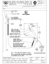
 A proper sidewall termination is required when the water heater is vented through a sidewall.
 Refer to the following pages for exhaust termination and air inlet clearances.
Approved Category III, Single Wall, Stainless Steel Venting Suppliers and Part Numbers
WARNING! Do not mix parts or fittings of different material types, and do not mix pipe, fittings, or
joining methods from different manufacturers. Combustion exhaust can contain carbon monoxide and
must be properly vented outside. Breathing abnormal amounts of carbon monoxide can result in seri-
ous injury or death.
Description
Heater Vent Kits
Z-FLEX®
NovaVENT™ Z-VENT™
4" Straight pipe - 6" length
100112407 2NVP4.5 2SVEPWCF0406
4" Straight pipe - 12" length
100112406 2NVP41 2SVEPWCF0401
4" Straight pipe - 24" length
100112404 2NVP42 2SVEPWCF0402
4" Straight pipe - 36" length
100112403 2NVP43 2SVEPWCF0403
4" Straight pipe - 48" length
100112402 2NVP44 2SVEPWCF0404
4" Adjustable straight pipe - 10"-18" adjustability
100112405 2NVAL4 2SVSPA04
4" 45 degree elbow
100112401 2NVE445 2SVEEWCF0445
4" 90 degree elbow
100112400 2NVE490 2SVEEWCF0490
4" Sidewall termination (4"Termination Hood)
100112419 2NVHTX4 2SVSHTX04
4" Vent termination tee
100112547 2NVTT4 2SVSTTF04
4" Rain Cap
100112415 2NVRC4 2SVSRCF04
4" Extreme weather rain cap
100112548 2NVWC4 2SVSHRC04
4" Horizontal drain tee
100112414 2NVHD4 2SVEDWCF04
4" Vertical drain tee
100112413 2NVVD4 2SVEVDP04
4" wall thimble length 4"-7" wall thickness
100112732 2NVWT4 2SVSWTF04
4" wall thimble length 5"-10" wall thickness
100112733 2NVWT4L 2SVSWTEF04
4" 3-in-1 adaptor (F-F adaptor, condensate
drain, & back-flow preventer)
100112585 2NVBFA4 2SVBFDPA04
4" F-F adaptor
100112399 2NVAFF4 2SVEEWCF0445
4" Backflow preventer w/ F-F adaptor
100112416 2NVBFU4 2ZVB04
4" exhaust / 3" intake DV concentric termina-
tion - 5"-10" adjustability
100112550 2NVHTC43S 2SVSHTC43S
4" exhaust / 3" intake DV concentric termina-
tion - 12"-18" adjustability
100112551 2NVHTC43 2SVSHTC43
4" Sidewall termination, adjustable pipe
100187853 2NVBV4 n/a
4" Wall Thimble, 3"-6" wall thickness
100187852 2NVBT4 n/a
15 Page
-Combuson Air Supply-
 This gas water heater requires an adequate source of clean air for combustion
and ventilation. Without sufficient air, your water heater may not operate
properly and may emit excessive and abnormal amounts of carbon monoxide
which may result in carbon monoxide poisoning or death.
WARNING
Before installing the water heater, you must determine the amount of air needed to supply this water
-

Before beginning

-
ing appliances (e.g., water heaters, furnaces, clothes dryers) in the same area. Do not include appliances
that are direct vented. Refer to the following example.
Your water heaters BTU/h rating is on the rating plate. The BTU/h ratings should be on the other
appliances’ rating plates. If you have trouble determining the BTU/h ratings, contact the manufacturer or
have a qualified person determine the ventilation requirements.
NOTICE: 

Gas Burning Appliance BTU/hRang
Gas Water Heater 140,000
Furnace 75,000
Dryer 20,000
Total 235,000
Example:
Gas Burning Appliance BTU/hRang
Gas Water Heater
Total
Your
appliances:
Does your installation space have sufficient combustion air?



-




Check for Chemicals:

-


outside air due to chemicals include:
 Beauty salons
 Photo processing labs
 Indoor pools
 
 Chemical storage areas
Products such as aerosol sprays, detergents, bleaches, cleaning solvents, gasoline, air fresheners, paint and
varnish removers, and refrigerants should not be stored or used near the water heater.
16 Page
Calculate the air volume of the room
Air requirements depend on the size of the room.

3

2

If there are large objects in the room (e.g., refrigerator, furnace, car), subtract their volume from the vol-

Air Volume = Room Volume - Object Volume

Calculate required air volume

feet per 1,000 BTU/h of the total input for all gas burning appliances in the same area.

3

3
/ 1000 (btu/h)
Example:
(235,000 / 1000) x 50 = 11,750
If the air volume of the room is less than the required air volume, you must direct vent the water heater
-

If the air volume of the room is greater than the required air volume, it may be possible to install the


as furnaces, whole house fans, and clothes dryers draw air out of your home. If they draw air out faster



-

Install with outside ventilation


Supplying outside air to the water heater typically requires two openings. One opening must be within 12

opening is not preferred, you may use a single opening to outside air if the minimum free area is sized accord-
ing to Table 1


Determine type of ventilation

1. Direct to outdoors
2. 
3. Horizontal ducts
4. 

5. From a larger room inside the house (not recommended – refer to "Calculate the air volume of the room"
above to determine if the combined volume of the rooms may be adequate).
Determine minimum free area required for each vent opening

from “Before beginning”) and the type of vent used. Table 1 provides the minimum free area for each vent opening

17 Page
Calculate minimum size of vent openings and ducts

vents use louvers or grilles to protect the opening. The louver or grill itself blocks some of the free area, so the open-
ing may need to be larger to meet the minimum free area requirements.





 
 

 Each vent opening must be no smaller than 100 square inches .
 
 Rectangular ducts must have a minimum dimension of no less than three inches .
 All screens must have mesh ¼” or larger.
 -

 
Check that air source is clean and free of chemicals
-


See graphics on next page.
Table 1

indoor spaces.

Opening Source Minimum Free Area
Direct to outdoors* 1 sq. in. per 4,000 BTU/hr (see Figure 1, 2)
 1 sq. in. per 4,000 BTU/hr (see Figure 3)
Horizontal ducts 1 sq. in. per 2,000 BTU/hr (see Figure 4)
Single Opening 1 sq. in. per 3,000 BTU/hr (see Figure 5)
Two permanent openings
to another room**
1 sq. in. per 1,000 Btu/hr (see Figure 6)
Opening: 100 in.
2
MIN.
Minimum dimension of air openings:
no less than 3 in.

an outside wall.


18 Page
CombusonAirSupplyOpons
Gable vent
to outdoors
Install above
insulaon
Outlet air to
ac 1 in
2
per
4,000 btu/h
Inlet air from
the crawl space
Open foundaon vent
Confined
Space
Alternate
Air Inlet
1 in
2
per
4,000 btu/h
Direct to outdoors openings
 duct openings
Outlet air to
ac 1 in
2
per
4,000 btu/h
Inlet air duct
1 in
2
per
4,000 btu/h
Confined
Space
12” maximum
Gable vent
to outdoors
Install above
insulaon
SIngle opening
Confined
Space
1 in
2
per
3,000 btu/h
Alternave
Opening
Locaon
Two permanent openings
Two permanent
Openings
1 in
2
per
1,000 btu/h
12” maximum
12” maximum
Confined
Space
Horizontal duct openings
1 in
2
per
2,000 btu/h
Confined
Space
Outlet
Inlet
Outdoor
Air Ducts
1 in
2
per
2,000 btu/h
Direct to outdoors openings
Two permanent openings
Two permanent
Openings
1 in
2
per
4,000 btu/h
12” maximum
12” maximum
Confined
Space
19 Page
-Vent length and No. of Elbows-
The vent system must be sealed airtight. All seams and joints without gaskets must be sealed with high
heat resistant silicone sealant or UL listed aluminum adhesive tape having a minimum temperature rating
of 350 °F (177 °C). For best results, a vent system should be as short and straight as possible.
 This water heater is a Category III appliance and must be vented accordingly with any 4 in. (102
mm) vent approved for use with Category III or Special BH type gas vent.
 Follow the vent pipe manufacturers instructions when installing the vent pipe.
 Do not common vent this appliance with any other vented appliance. (Do not terminate vent
into a chimney. If the vent must go through the chimney, the vent must run all the way through
the chimney with Category III approved or Special BH vent pipe.)
 When the horizontal vent run exceeds 5 ft (1.5 m), support the vent run at 3 ft (0.9 m) intervals
with overhead hangers.
 The maximum length of exhaust vent piping must not exceed 60 ft (18.3 m).* Deduct 5 ft
(1.5 m) for each 90° elbow used in the venting system. Do not use more than 6 elbows. A 45°
elbow is equivalent to 2.5 ft of vent length.
*If vent termination kit 100187154 is used in the installation, the maximun length of exhaust vent pipe
must not exceed 55 ft (16.8 m) , and the vent run must not exceed 5 elbows. Vent termination kit
100187154 also has specific DIP switch settings. Refer to p. 22.
Vent type Diameter Max. No. of Elbows Max. Vertical and Horizontal (Total) Vent Length
Intake** 3 in. (76 mm) 6** 60 ft (18.3 m )*
Exhaust 4 in. (102 mm) 5 55 ft (16.8 m )*
*For each 90° elbow added, deduct 5 ft (1.5m) from max. vent length.
**For Intake vent, refer to the above table of the installation of 6 elbows and 60 ft.
Vent type Diameter Max. No. of Elbows Max. Vertical and Horizontal (Total) Vent Length
Intake 3 in. (76 mm) 6 60 ft (18.3 m )*
Exhaust 4 in. (102 mm) 6 60 ft (18.3 m )*
*For each 90° elbow added, deduct 5 ft (1.5m) from max. vent length.
No. of Elbows
Max. Vertical or Horizontal
Vent Length
No. of Elbows
Max. Vertical or Horizontal
Vent Length
0 60 ft (18.3m) 4 40 ft (12.2 m)
1 55 ft (16.8 m) 5 35 ft (10.7 m)
2 50 ft (15.2 m) 6 30 ft (9.1 m)
3 45 ft (13.7 m)
Excludes elbow termination, rain caps, or the 4 in. (102 mm) Concentric termination.
No. of Elbows
Max. Vertical or Horizontal
Vent Length
No. of Elbows
Max. Vertical or Horizontal
Vent Length
0 55 ft (16.8 m) 3 40 ft (12.2 m)
1 50 ft (15.2 m) 4 35 ft (10.7 m)
2 45 ft (13.7 m) 5 30 ft (9.1 m)
Excludes sidewall termination.
Installaon
Installaon Manual
Standard Vent Terminations (See the next table for vent termination 100187154.)
Installation with vent termination kit 100187154
20 Page
-DIP Switch Settings for Vent Length-
Single Pipe with Room-Air Intake
HorizontalInstallaon
Wall
Hanger
Sidewall vent

Vertical
condensation
drain**
Backflow
preventer*
*Backflow preventer (Recommended for freezing weather conditions: 36 °F (2 °C) and below).
**Vertical condensation drain must be installed in accordance with local codes. It is required to be installed in the vent-
ing system when there is more than 5 ft (1.5 m) of equivalent vent length, not including the sidewall termination. 90° elbow
is equivalent to 5 ft (1.5 m) of vent length.
VercalInstallaon
Roof

Roof
Fire stop
Hanger
Vertical
condensation
drain**
Backflow
preventer*
Rain cap
110U Indoor
310U Indoor
510U Indoor
(Upper bank of DIP switches)
Vent length
No. 6 : O N
No. 7 : OFF
No. 8 : OFF
No. 3 : O N
No. 4 : OFF
No. 5 : OFF
0 to 60 ft
(0 to 18.3 m)
OFF
ON
1 2 3 4 5 6 7 8 9 10
OFF
ON
1 2 3 4 5 6 7 8
DIP switch settings for single pipe with room-air intake
 Improper venting of this appliance can result in excessive levels of carbon
monoxide which can result in severe personal injury or death.
 Improper installation can cause nausea or asphyxiation, severe injury
or death from carbon monoxide and flue gases poisoning. Improper
installation will void product warranty.
 Specific DIP switch settings are required depending on the length of your
vent run and the type of vent installation. Refer to the following sections
for details:
 Single Pipe with Room Air (page 20)
 Two-pipe Direct Vent (page 21)
 Vent kit of 100187154 (page 22)
 Outdoor Installation (page 22)
WARNING
  • Page 1 1
  • Page 2 2
  • Page 3 3
  • Page 4 4
  • Page 5 5
  • Page 6 6
  • Page 7 7
  • Page 8 8
  • Page 9 9
  • Page 10 10
  • Page 11 11
  • Page 12 12
  • Page 13 13
  • Page 14 14
  • Page 15 15
  • Page 16 16
  • Page 17 17
  • Page 18 18
  • Page 19 19
  • Page 20 20
  • Page 21 21
  • Page 22 22
  • Page 23 23
  • Page 24 24
  • Page 25 25
  • Page 26 26
  • Page 27 27
  • Page 28 28
  • Page 29 29
  • Page 30 30
  • Page 31 31
  • Page 32 32
  • Page 33 33
  • Page 34 34
  • Page 35 35
  • Page 36 36
  • Page 37 37
  • Page 38 38
  • Page 39 39
  • Page 40 40
  • Page 41 41
  • Page 42 42
  • Page 43 43
  • Page 44 44
  • Page 45 45
  • Page 46 46
  • Page 47 47
  • Page 48 48
  • Page 49 49
  • Page 50 50
  • Page 51 51
  • Page 52 52
  • Page 53 53
  • Page 54 54
  • Page 55 55
  • Page 56 56
  • Page 57 57
  • Page 58 58
  • Page 59 59
  • Page 60 60

A.O. Smith GT15-110U-O Owner's manual

Category
Water heaters & boilers
Type
Owner's manual

Ask a question and I''ll find the answer in the document

Finding information in a document is now easier with AI