A.O. Smith R4LR-240E User manual

Type
User manual
Electric Tankless
Water Heater
Keep this manual near the water heater for future reference whenever maintenance, adjustment or service is required.
Retain your original receipt as proof of purchase.
IMPORTANT SAFETY INFORMATION .............................2
GENERAL INFORMATION ...............................................5
INSTALLATION ...............................................................11
OPERATION ...................................................................15
TROUBLESHOOTING ....................................................17
SERVICE .........................................................................22
WIRING DIAGRAMS .....................................................29
APPENDIX ......................................................................34
Table of Contents ..............................Page
°F
°C
ENTER
°F
°C
ENTER
PLEASE DO NOT RETURN THIS UNIT TO THE
STORE.
Read this manual and the labels on the water heater before you install,
operate, or service it. If you have di culty following the direc ons, or
United States: 1-877-817-6750
Canada: 1-800-265-8520
We can help you with installation, operations, troubleshooting, or
maintenance. Before you call, write down the model and serial number from
on, opera on, or service can damage the water heater, your
house and other property, and present risks including re, scalding, electric
shock, and explosion, causing serious injury or death.
0818
100306524_2000558984 (REV. B)
Installa on Instruc ons
and Use & Care Guide
SAFETY
IMPORTANT SAFETY INFORMATION
Important informa on to keep...
Fill out this sec on and keep this
manual for reference.
Date Purchased:
Model number:
Serial number:
Maintenance performed: Date:
This is the safety alert symbol. It is used to alert you to
poten al physical injury hazards. Obey all safety mes-
sages that follow this symbol to avoid possible property
damage, serious injury or death. Do not remove any
permanent instruc ons, labels, or the data plate from either the outside of
the water heater or on the inside of the access panels. Keep this manual
near the water heater.
DANGER
Read and follow all safety messages and instruc ons in
this manual.
DANGER indicates hazardous
situa on that, if not avoided, will
result in death or serious injury.
WARNING
WARNING indicates a hazardous
situa on that, if not avoided, could
result in death or serious injury.
CAUTION
CAUTION indicates a hazardous
situa on that, if not avoided, could
result in minor or moderate injury.
NOTICE
NOTICE indicates prac ces not
related to physical injury.
SAFETY
T
o reduce the risk of property
damage, serious injury or death,
read and follow the precau ons below,
all labels on the water heater, and
the safety messages and instruc ons
throughout this manual.
General Requirements
unit in accordance with local
codes, or in the absence of local
codes, with the current edition
of the National Electrical Code:
ANSI/NFPA 70 in the USA or
CSA standard C22.1 Canadian
Electrical Code, Part 1 in Canada.
heating, and air conditioning
codes during installation.
RISKS DURING INSTALLATION
AND MAINTENANCE
WARNING
Electric Shock Risk
Contact with the electrical
parts inside the water heater
can result in severe injury or
death from electrical shock:
Disconnect power by opening the
circuit breaker(s) before installing
or servicing.
SOME MODELS ARE CONNECTED
TO MORE THAN ONE BRANCH
CIRCUIT, AND MORE THAN ONE
DISCONNECT SWITCH MAY BE
REQUIRED TO DE ENERGIZE THE
EQUIPMENT. ALL BRANCH CIR
CUITS MUST BE DISCONNECTED
PRIOR TO SERVICE.
confirm that power is off before work-
ing on or near any electrical parts.
Be sure the cover is reinstalled and
secured after servicing to reduce
the risk of fire and electric shock.
RISKS DURING OPERATION
WARNING
Scalding Risk
This water heater
can make water hot
enough to cause
severe burns instantly, resulting in
severe injury or death.
s howering.
install Thermostatic Mixing
Valves (temperature limiting
valves) at each point of use.
These valves automatically mix
hot and cold water to limit the
temperature at the tap. Mixing
valves are available at your local
hardware store or from your
plumbing supplier. Follow the
installation and adjustment of the
valves.
set point is factory set to 120°F
to reduce the risk of scalding.
Exception: single chamber (point-
of-use) models are factory set to
approximately 105°F.
the risk of scalding, but even at
120°F, hot water can scald. If you
choose a higher temperature,
Thermostatic Mixing Valves
located at each point of use are
particularly important to help
avoid scalding.
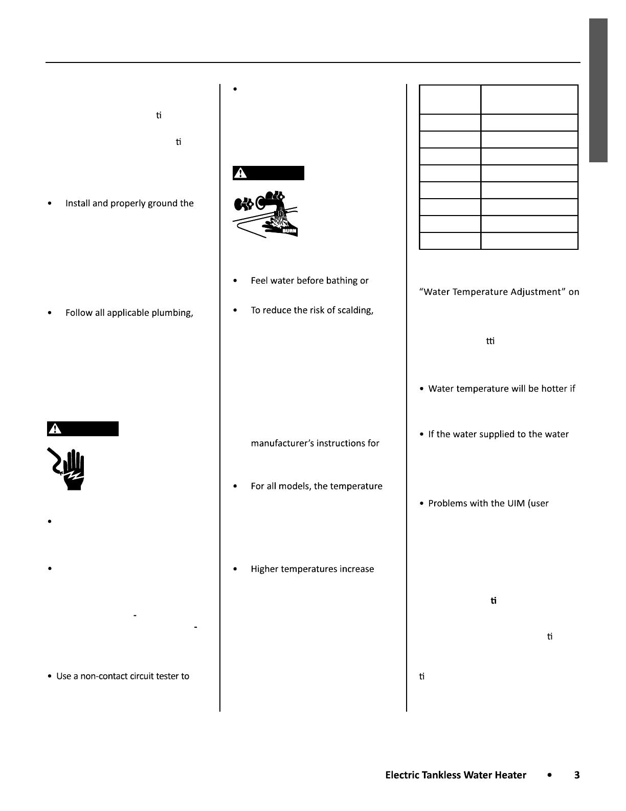
Temperature Time to Produce a
Serious Burn
120°F (49°C) More than 5 minutes
125°F (52°C) 1½ to 2 minutes
130°F (54°C) About 30 seconds
135°F (57°C) About 10 seconds
140°F (60°C) Less than 5 seconds
145°F (63°C) Less than 3 seconds
150°F (66°C) About 1½ seconds
155°F (68°C) About 1 second
For information about changing the
factory temperature setting, refer to
page 15.
Even if you set the water heater set
point to a low se ng, higher tem-
peratures may occur in certain circum-
stances:
someone adjusted the temperature
set point to a higher setting.
heater is pre-heated (for example,
by another water heater), the tem-
perature of the water may be high-
er than the temperature set point.
interface on two- or four-chamber
models) or other malfunctions may
result in higher than expected water
temperatures.
To reduce the risk of unusually hot wa-
ter reaching the xtures in the house,
install Thermosta c Mixing Valves at
each point of use.
If anyone in your home is at par cular
risk of scalding (for example, the el-
derly, children, or people with disabili-
es) or if there is a local code or state
law requiring a certain water tempera-
ture at the hot water tap, then these
SAFETY
precau ons are par cularly important.
According to a na onal standard, Ameri-
can Society of Sanitary Engineering
(ASSE 1070), and most local plumbing
set point should not be used as the sole
means to regulate water temperature
and avoid scalds.
Properly adjusted Thermosta c Mixing
Valves installed at each point of use
set point to a higher se ng without
increasing the risk of scalds. A higher
temperature can help provide proper
water temperatures for appliances such
as dishwashers and washing machines.
WARNING
Fire Risk
To reduce the risk of a
fire that could destroy
your home and seri-
ously injure or kill people:
easily such as paper or clothes next
to the water heater.
is in place. This cover keeps debris
from entering and potentially being
ignited, and helps keep any internal
fires from spreading.
ing wet. Immediately shut the water
heater off and have it inspected by
a qualified person if you find that
the wiring or control board have
been exposed to water in any way
(e.g., leaks from plumbing or leaks
from the water heater itself). Such
leaks can damage property and
could cause a fire risk. If the water
heater is subjected to flood condi-
tions or has been submerged in
water, the entire water heater must
be replaced.
erly according to the instructions on
page 13. Use a UL listed or CSA
approved strain relief. Connect the
ground wire to the ground lug. (The
ground lug is identified by a green
and white ground label inside the
water heater.)
Water Contamination Risk
Do not use chemicals that could
contaminate the potable water sup-
ply. Do not use piping that has been
treated with chromates, boiler seal, or
other chemicals.
GENERAL INFO
GENERAL INFORMATION
Introduction
necessary for the installation,
operation, and maintenance of
the water heater.
the rating plate which is attached
to the side panel of the water
heater.
instructions completely before
installing this product.
or questions regarding this
equipment, consult the
manufacturer or its local
representative.
This appliance is an on-demand,
electric tankless water heater. It is
designed to efficiently supply endless
hot water for your needs.
A built-in alarm is included. If water
leaks inside your electric water
heater, an alarm will sound to provide
warning. Simply turn off power to the
water heater at the circuit breakers,
turn off the water supply, then correct
the leak.
Your water heater also includes
on-board self diagnostics. If the
system produces an error code, see
following pages:
page 19.
Component
Descriptions
Temperature and Pressure
Relief Valve
In most cases, you are not required
to install a temperature and pressure
relief valve (T&P valve). However,
some local codes do require the
installation of a T&P Valve. If a T&P
valve must be installed, install it on
the hot outlet pipe according to the
local code.
If you install a T&P valve, turn on the
water supply to ensure that no water
drips from it. Next, operate the valve
manually two or three times to purge
the trapped air from the top of the
valve. Verify that water has stopped
flowing completely before connecting
the discharge pipe to the valve.
NOTICE: If a temperature and
pressure relief valve is installed, it
must be piped by minimum 1 inch
pipe to a suitable drain capable of
discharging 10 GPM. A splash cover
must be included to protect the
area of attachment to the wall. The
manufacturer will not be responsible
for any water damage that may occur.
WARNING! Do not cap or plug the
T&P relief valve or discharge pipe.
Component Identification: Point-of-Use Models (RPV, CPV)
POWER
SUPPLY
TERMINAL
BLOCK
L1
L2/N
GND
T-Aux
T-In
T-Out
T-Aux
Auxiliary thermistor
T-In
Inlet thermistor
T-Out
Outlet thermistor
Thermistor* Connections
OUTLET INLET
Outlet Thermistor *
(Connects to T-Out)
Auxiliary Thermistor *
(Connects to T-Aux)
Inlet Thermistor *
(Connects to T-In)
* Often referred to
as a temperature
sensor.
Heating Element
(Behind inlet/outlet)
Continued on the next page...
GENERAL INFO
Component Identification: Two-Chamber Models (R2V, C2V)
Inlet Thermistor *
(connects to TH-IN)
OUTLET INLET
TH-IN
Inlet thermistor
TH-1
Intermediate thermistor
TH-2
Outlet thermistor
Thermistor* Connections
* Often referred
to as a
temperature
sensor.
L1
L2
TH-1
TH-IN
Intermediate
Thermistor *
(connects to
TH-1)
Outlet Thermistor *
(connects to TH-2)
HEATING ELEMENTS
Access Plate
(for draining)
TH-2
NOTICE:
The user interface is
described in Figure 7,
page 16.
Component Identification: Four-Chamber Models (R4L, C4L, R4M, C4M)
Inlet Thermistor *
(connects to TH-IN)
INLET
L1
L2
TH-1
TH-3
TH-4
Intermediate
Thermistor *
(connects to
TH-1)
TH-2
TH-IN
L1
L2
TH-IN
Inlet thermistor.
TH-1 Intermediate thermistor
TH-4
Outlet thermistor
Thermistor* Connections
* Often referred to as a
temperature sensor.
TH-2 Intermediate thermistor
TH-3 Intermediate thermistor
OUTLET
Outlet Thermistor *
May be located on
outlet elbow.
(connects to TH-4)
Intermediate Thermistor *
(connects to TH-3)
Intermediate
Thermistor *
(connects to
TH-2)
Access Plates
(for draining)
Element Element Element Element
NOTICE:
The user interface is
described in Figure 7,
page 16.
GENERAL INFO
Models
Point-of-Use:
RPV, CPV
Two Chamber:
R2V, C2V
Four Chamber:
R4L, C4L, R4M, C4M
Wiring & Circuit Breaker
Requirements
Water Connections
Weight
lbs. (kg)
8 lbs. (3.6 kg) 13 lbs. (5.9 kg) 20 lbs. (9 kg)
Water Heater
Dimensions*
(H 42.2cm x W 16.5cm x D 18.3 cm) (H 45.1 cm x W 29.2 cm x D 15.6 cm) (H 46 cm x W 43.2 cm x D 15.6 cm)
* Height dimension includes the distance from the bottom of the heater to the highest point of the inlet/outlet.
Width dimension includes the mounting tabs on the left-hand and right-hand sides (two- and four-chamber models).
NOTE:
without incurring obligations.
reducing valve with a bypass should be installed in the cold water inlet line.
General Specifications
GENERAL INFO
Electrical Requirements
Follow these steps to determine the electrical requirements for your water heater:
2.) Locate that model number in one of the tables listed below.
For example, if your model is RPVA-24-K, find *P**-24-K in the appropriate table.
Models within each table are sorted by Voltage first, then by Wattage per Element (KW).
Follow the requirements listed for your model.
Point-of-use models are listed below.
Two-chamber models: page 9.
Four-chamber models: page 10.
Use copper conductors only.
Point-of-Use Models
(For potable water heating only. Not for space heating.)
NOTICE: Models sorted by Voltage, then by Wattage per Element.
Model Recommended
Breaker Size
(Amps)
Voltage Number
of
Elements
Wattage
per Element
(KW)
Current per
Breaker
(Amps)
Recommended
Wire Size
*
(AWG)
Element Type
*P**-24-K 20 120 1 2.4 20.00 12 Single
*P**-30-K 25 120 1 3 25.00 10 Single
*P**-35-K 30 120 1 3.5 29.17 10 Single
*P**-40-X 20 208 1 4 19.23 12 Single
*P**-78-X 40 208 1 7.8 37.5 8 Single
*P**-35-E 15
240
1 3.5 14.58 14 Single
*P**-45-E 20
240
1 4.5 18.75 12 Single
*P**-55-E 25
240
1 5.5 22.92 10 Single
*P**-70-E 30
240
1 7 29.17 10 Single
*P**-80-E 40
240
1 8 33.33 8 Single
*P**-90-E 40
240
1 9 37.50 8 Single
*P**-120-E 50
240
1 12 50
6
Dual
*P**-30-Y 15 277 1 3 10.83 14 Single
*
All wiring/conductors must be rated for 90°C or greater.
Follow all code requirements.
GENERAL INFO
Point-of-Use Models
(For potable water heating only. Not for space heating.)
NOTICE: Models sorted by Voltage, then by Wattage per Element.
Model Recommended
Breaker Size
(Amps)
Voltage Number
of
Elements
Wattage
per Element
(KW)
Current per
Breaker
(Amps)
Recommended
Wire Size
*
(AWG)
Element Type
*P**-40-Y 15 277 1 4 14.44 14 Single
*P**-60-Y 25 277 1 6 21.66 10 Single
*P**-73-Y 30 277 1 7.3 26.35 10 Single
*P**-90-Y 40 277 1 9 32.49 8 Single
*
All wiring/conductors must be rated for 90°C or greater.
Follow all code requirements.
Two-Chamber Models
(For potable water heating only. Not for space heating.)
NOTICE: Models sorted by Voltage, then by Wattage per Element.
Model Recommended
Breaker Size
(Amps)
Voltage Number of
Elements
Wattage per
Element (KW)
Current per
Breaker
(Amps)
Recommended
Wire Size
*
(AWG)
Element
Type
*2**-140-X
40 amps each
(2 circuits)
208 2 7 33.65 8 Single
*2**-120-E
60 amps 240 2 6.1 50.83 6 Single
*2**-140-E
60 amps
240 2 7 58.34 6 Single
*2**-160-E
40 amps each
(2 circuits)
240 2 8 33.33 8 Single
*2**-180-E
40 amps each
(2 circuits)
240 2 9 37.5 8 Single
*
All wiring/conductors must be rated for 90°C or greater.
GENERAL INFO
Four-Chamber Models (Single Phase)
For potable water heating only. Not for space heating.
NOTICE: Models sorted by Voltage, then by Wattage per Element.
Model Recommended
Breaker Size
(Amps)
Voltage Number of
Elements
Wattage per
Element (KW)
Current per
Breaker
(Amps)
Recommended
Wire Size
*
(AWG)
Element
Type
*4**-280-X 70 amps each
(2 cirucits)
208 4 7 67.31
6
Single
*4**-180-E 40 amps each
(2 circuits)
240 4 4.5 37.50 8 Single
*4**-220-E 50 amps each
(2 circuits)
240 4 5.5 45.83 6 Single
*4**-240-E 60 amps each
(2 circuits)
240 4 6 50.00
6
Single
*4**-280-E 60 amps each
(2 circuits)
240 4 7 58.33
6
Single
*4**-320-E 70 amps each
(2 circuits)
240 4 8 66.67
6
Single
*
All wiring/conductors must be rated for 90°C or greater.
INSTALLATION
INSTALLATION
Getting Started
Clearances
See Figure 1 or Figure 2.
Top Clearance: A minimum of 12
inches (30.5 cm) is required for
removal and maintenance of heating
elements and to provide access for
plumbing connections.
Side Clearance: Allow an 8 inch (20.3 cm)
minimum horizontal space for the
heater. This horizontal clearance will
allow for the removal of protective
cover screws and provide access to
electrical wires that will enter the
heater from the side.
Bottom Clearance: At a minimum,
maintain a bottom clearance of 8
inches (20.3 cm) for single chamber
models or 15 inches (38.1 cm) for 2- or
4-chamber models. Do not store any
items underneath the water heater.
Front Clearance: Maintain a minimum
clearance of 8 inches (20.3 cm). In the
absence of a door or removable access
panel in front of the heater, allow a
minimum of 15 inches (38.1 cm) front
clearance. This will allow for cover
removal and ease of service. See
Figure 1 or Figure 2.
Code Compliance
unit in accordance with local
codes, or in the absence of local
codes, with the current edition
of the National Electrical Code:
ANSI/NFPA 70 in the USA or
CSA standard C22.1 Canadian
Electrical Code, Part 1 in Canada.
plumbing, heating, and air
conditioning codes during
installation.
1
Choose a
Location
be installed indoors only.
clean, dry area that is as close to
the point of use as possible. Do
not install it in a bath enclosure or
shower stall.
must be protected from freezing.
Do not install your water heater
where it may be subjected to
freezing temperatures.
to dampness, high humidity,
moisture, or dust. Such locations
include crawl space under a house
or building, in the garage (in
regions prone to high humidity)
and in the attic (unless the attic
has been converted to a living
space).
will not be accessible to children.
WARNING! This water heater
can make water hot enough to
cause severe burns instantly,
resulting in severe injury or death.
is accessible and that minimum
Wall or
adjacent
object
12
(30.5 cm)
15+
( +)
2-Chamber or
4-Chamber
Water Heater
Minimum Clearances
8
(20.3 cm)
8
(20.3 cm)
°F
°C
ENTER
Front
View
Side View
Wall
Front Clearance:
15 + (38.1 cm +)
Install one
each corner.
Figure 1.
Side View
Wall
Wall or
adjacent
object
12
(30.5 cm)
8+
(20.3 cm +)
Front Clearance:
15 + (38.1 cm +)
Single
Chamber
Water Heater
Minimum Clearances
8
(20.3 cm)
8
(20.3 cm)
Front
View
Figure 2.
NOTICE: Point-of-use models may be mounted
horizontally. See Figure 3, page 12.
inlet/outlet.)
INSTALLATION
clearances are observed. Do
not store any items underneath
the water heater, and do not
store flammable liquids or other
flammable materials near the
water heater. This is important
for safety and future service. See
underneath condensate lines.
protection against water damage,
is recommended to be installed
under the water heater in case of
leaks. In addition, you may install
an active water leak detector with
a shutoff valve which can turn off
the water supply in the event of
a leak. The manufacturer is not
responsible for damage due to
water leaks.
2
Mount Your
Water Heater
1. Unpack the heater from the
shipping carton, but do not cut
the shipping carton with a sharp
instrument.
2. Stand the unit upright and
remove the plastic wrap.
3. Remove the screws that secure
the protective cover.
4. Remove the cover. If your water
heater has a user interface display
(UIM) , unplug its ribbon cable
from the control board in the
water heater. (A UIM is shown in
Figure 7, page 16.)
NOTICE: Be sure to remember
where to plug it back in later.
When the me comes to plug the
connector back into the control
board, it must be oriented cor-
rectly. We recommend marking
the connector and board with a
marker. You will then be able to
align the marks later. See also
Figure 5, page 14.
5. If you have a point-of-use model,
locate the four mounting holes
in the back plate. (If you have
a two- or four-chamber model,
there are two mounting tabs on
each side of your water heater.)
6. Two- or four-chamber water
heaters only:
Apply one stando bumper to
each corner on the back of the
water heater. Stando s are
provided. These stando s must
be installed so the water heater
can vent properly. See Figure 1,
page 11.
7. Determine the mounting location
on the wall, then verify your
page 11.)
8. Position the unit against the wall.
Make sure that the unit is level.
NOTICE: Two-chamber and
four-chamber models must
be oriented with the inlet and
outlet facing upward. However,
point-of-use (POU) models may
be oriented horizontally as
described in Figure 3. To mount
a POU water heater horizontally,
follow the instructions on page
34.
9. Secure the water heater to the
wall or other suitable structure
with screws, bolts, or anchors
as appropriate. Ensure that the
mounting surface and fasteners
will support the weight of the
water heater. (You will reinstall
cover later.)
Figure 3.
water heater:
Horizontal
3
Connect the
Water Lines
NOTICE:
DO NOT apply heat to the water
lines, nipples, or any fitting on the
water heater. Heat from soldering
may damage the heat exchanger.
tape) is the only sealer that may
be used on the threads of the
inlet and outlet fittings. DO
NOT use pipe dope or PVC/CPVC
primer and glue on the threads
of the inlet and outlet fittings.
Exposure to these compounds
will damage the nipples, causing
leaks.
the hot and cold water lines to
INSTALLATION
the heater. The second wrench
must be used
fittings securely because they are
designed to turn freely.
are recommended for your
installation.
with this water heater. Do not
introduce pool or spa water, or
any chemically treated water into
the water heater.
regenerated water softener or a
water supply of salt water.
damage caused by water quality.
pressure: 50 to 60 psi. Higher
pressures require a pressure
reducing valve.
an attic require a bleed air separator.
be installed where water hammer
exists.
NOTICE: Do not supply electrical
power to your water heater yet. If you
Figure 4 .
do so at this point, you will damage
your heating element(s).
1. Make sure that the water supply
is turned off.
2. Connect the hot water line to the
hot outlet of the water heater.
(Figure 4.)
3. Connect the cold water line to
the cold inlet of the water heater.
(Figure 4.)
4. Open the valve on the main water
line to supply water to the heater.
5. Open several hot water fixtures
and allow water to run through
the water heater for several
minutes to purge air from the
water lines.
6. Check for water leaks. Correct
any that are found.
7. If you installed a T&P valve to
meet local code requirements,
operate it manually several
times to allow any trapped air to
escape.
NOTICE: Failure to purge air from
the water lines can leave air pockets,
causing damage to the heating
elements when power is applied.
4
Install Electrical
Service
WARNING
Failure to observe these warnings
could lead to an improper
installation, and the risks include fire,
electrical shock, and/or death:
Installation must be performed
by a qualified installer. The
installer (licensed professional)
is responsible for the correct
installation of the water heater
and for compliance with all
national, state / provincial, and
local codes.
Refer to the electrical
requirements and electrical
schematic during installation and
service.
Turn off power service at the
main circuit breaker(s) prior
to installation. Working on an
energized circuit can result in
severe injury or death from
electrical shock.
Some models must be connected to
more than one branch circuit, and
more than one disconnect switch
may be required to de-energize the
equipment. All branch circuits must
be disconnected during installa on
or service.
Install and properly ground the
unit in accordance with local
codes, or in the absence of local
codes, with the current edition
of the National Electrical Code:
ANSI/NFPA 70 in the USA or CSA
standard C22.1 Canadian Electrical
Code, Part 1 in Canada.
NOTICE:
When using stranded wire, make sure
that all strands are secure inside the
terminal block. A loose strand can
cause a short circuit and damage the
circuit board.
1. Be sure the electrical power to
the water heater is turned OFF
at the circuit breaker panel (or
2. Using a non-contact circuit tester,
check the wiring to make certain
the power is OFF.
ng
plate and ensure that the electrical
INSTALLATION
page 29.)
If you marked the board and con-
nector during earlier steps, align
the marks when plugging the con-
nector in.
NOTICE: The plug must be ori-
ented correctly. If you plug it in
backwards, it will not cause dam-
age, but the display will not work.
If the display does not work a er
you have completed installa on,
follow these steps:
A.) Disconnect power at all
branch circuits.
B.) Disconnect the plug.
C.) Rotate the plug 180 degrees,
then plug it back in.
WARNING! Be sure the cover is
secured to reduce the risk of re
and electric shock.
9. Turn on power to the water heater.
10. Verify proper operation.
(ampacity) and circuit breaker
ra ng/type are correct for this
water heater.
NOTICE: The electrical
requirements for your model are
which starts on page 8.
4. Connect the electrical service
as described in
(starting on page
8).
There is a wiring diagram label on
manual.
5. Do the following:
Check all electrical
connections to make sure that
they are correct and secure.
Make sure that the
supply voltage, wiring
size (ampacity), circuit
breaker rating and type are
on page 8).
Label all breakers/connections
to the water heater.
6. Ensure that all air has been
purged from the water lines by
opening several hot water fixtures
near the water heater. Run water
through the water heater until all
air is purged from the lines.
7. Two- and four-chamber models
only: Plug the connector end
the control board. See Figure 5.
(Plug it in where you see two rows
of header pins close together, five
pins in each row.) If necessary,
in the wiring diagram for your
Operating instructions are listed
on page 15.
5
Test Water
Heater Operation
1. At nearby hot water faucets, turn
water on medium-low.
You may hear a hissing or
crackling noise from the heat
exchanger after the unit begins
to heat water. This is normal.
2. Check water at the fixtures to
make sure that the water is being
heated.
NOTICE:
Your water heater includes on-board
self diagnos cs. If an error occurs, the
fy
more informa on (page 17 or 19).
Ribbon Cable Red Band
on Board
NOTICE:
When plugging the display
(User Interface Module)
into the control board,
orient it as shown in this
graphic.
Ribbon Cable
Connector
Control Board
Figure 5.
Two- and four-chamber models only:
OPERATION
Water Temperature
Adjustment
WARNING
Scalding Risk
This water heater
can make water hot
enough to cause
severe burns instantly, resulting in
severe injury or death. Before
a emp ng to adjust the temperature
instruc ons are not clear, contact a
quali ed service technician.
To adjust your temperature se ng, re-
fer to one of the following procedures.
Point -of-use models only:
To adjust the temperature setting,
OPERATION
turn the temperature adjustment
knob as described below. This knob
can be found at the top of the circuit
board next to the plumbing connec-
ons. (Figure 6.)
The factory se ng is approximately
105°F (+/-1°F).
turn the knob to the left (counter
clockwise).
turn the knob to the right
(clockwise).
to turn the knob.
The water temperature set point can
be adjusted within a range of 90°F
(32C) and 140°F (60 °C).
Two- or four-chamber models
only:
The water temperature set point can
be adjusted within a range of 90°F
(32C) and 140°F (60 °C).
To change the set temperature,
1. Press and release either the
UP or DOWN button (Figure 7,
page 16). The display will
blink and allow you to adjust the
temperature set point.
2. Press and hold the UP or
DOWN button to scroll through
the temperatures quickly.
Single presses will adjust the
temperature setting one degree
at a time.
3. Press the ENTER button to
confirm.
Continued on the next page...
PLUMBING CONNECTIONS
BEHIND CIRCUIT BOARD
TEMPERATURE ADJUSTMENT KNOB
TURN KNOB TOWARD LEFT
(COUNTER-CLOCKWISE )
TURN KNOB TOWARD RIGHT
(CLOCKWISE )
SCREWDRIVER.
POINT-OF-USE MODELS ONLY:
TEMPERATURE ADJUSTMENT KNOB ON INTERNAL CIRCUIT BOARD
Figure 6.
OPERATION
To toggle between Fahrenheit and
Celsius,
1. Press and hold the DOWN button
for five seconds. See Figure 7.
2. The °F or °C LED will illuminate,
and the 7-segment LED will
display the temperature set point
in the appropriate units.
°F
°C
ENTER
°F
En on
Figure 7 .
Two and Four Chamber Models Only:
TROUBLESHOOTING
Error Codes for Point-of-Use Models
If you have a two- or four-chamber model, see page 19.
WARNING
Electric Shock Risk
Contact with the electrical parts inside the water heater can result in severe injury or death from electrical shock:
Disconnect power by opening the circuit breaker(s) or removing the fuses before installing or servicing.
Some models are connected to more than one branch circuit, and more than one disconnect switch may be
required to de-energize the equipment. All branch circuits must be disconnected prior to service.
The LED on the circuit board will display an error code as a ash pa ern. The ash pa ern is displayed as follows:
rst digit of the error code is ashed in RED.
GREEN ash separates the rst and second digits.
ashed in RED.
See the example below. Components are iden ed in Figure 8, page 18.
Example from the Table Below:
Flash Code Sequence: 3-6 (Freeze Warning). The 3-6 code would be displayed like this:
3 6
3 red ashes
A er you iden fy the code, locate its descrip on and solu on in the table.
NOTICE:
ple codes; verify all sequences.
ple error codes, the LED will pause between each one. The GREEN LED will ash twice a er the last error
code. The error codes will then repeat.
hear the ash code, press the mode bu on for two seconds. This will turn the audible beeper on. See Figure 8,
page 18.
Flash Code
Sequence
Description Action / Solution
1-1 Disable switch open (hardware
jumper is not installed on the circuit
board).
Install the missing jumper(s) on the circuit board as shown in Figure 8, page 18.
Both jumpers must be in place.
1-2 T-In thermistor is open. Check wiring. Replace as necessary.
1-3 T-Out thermistor is open. Check wiring. Replace as necessary.
1-7 Water temperature above 145°F has
been detected. (This code will clear
when the condi on is corrected.)
1. Turn o all power to the water heater. Open a nearby hot water xture
and allow water to run through the heater for about 5 minutes. Check the
resistance of the temperature sensors (thermistors). If one of the thermistors
has a resistance that is much higher than the others, replace that thermistor.
2. If the issue persists, the circuit board (control board) may need to be replaced.
Contact Technical Support.
TROUBLESHOOTING
Continued on the next page...
TROUBLESHOOTING
LED STATUS LAMP
INTERNAL CIRCUIT BOARD
MODE BUTTON:
(PRESS FOR TWO
SECONDS TO TURN
AUDIBLE BEEPER
ON)
PLUMBING CONNECTIONS
BEHIND CIRCUIT BOARD
REQUIRED JUMPERS (2)
TOP OF INTERNAL CIRCUIT BOARD
OPEN PINS (3)
BACK OF CASE
LEAK SENSOR
Figure 8 .
Flash Code
Sequence
Description Action / Solution
1-8 Leak detected. Shut o all power to the water heater. Check for water leaks. Correct any leaks
found. Dry the leak sensor (Figure 8), then dry the circuit board completely before
restoring power.
2-1 Tank is not full of water. Ensure that the heater is lled with water and that there is no air trapped inside.
Make sure that the back ow preventer or check valve is opera ng properly and is
lled and there are
no leaks, connect level detect spades on the circuit board to ground. If the code
is accompanied by a clicking sound that is present when water is running, check
the elements.
3-4 Cri cal error (displayed when other
errors are triggered)
Follow the Ac on/Solu on for the other errors that are displayed.
3-6 Freeze Warning (T-In thermistor
detects that incoming water is lower
than 40°F). This error may also
occur when an open thermistor is
detected.
1. Check wiring to the T-In thermistor. Ensure that the T-In thermistor is not faulty.
2. If incoming water is below 40°F, Turn o power to the water heater, close o
its water supply, then drain the water heater. Wait un l the incoming water is
above 40°F, then restore service.
TROUBLESHOOTING
Error Codes for Two and Four Chamber Models
If you have a point-of-use model, see page 17.
WARNING
Electric Shock Risk
Contact with the electrical parts inside the water heater can result in severe injury or death from electrical shock:
Disconnect power by opening the circuit breaker(s) or removing the fuses before installing or servicing.
Some models are connected to more than one branch circuit, and more than one disconnect switch may be
required to de-energize the equipment. All branch circuits must be disconnected prior to service.
Display Description Action / Solution
E02 Hardware determined that the
heated water has exceeded the
temperature limit.
Turn o power to the water heater. Contact Technical Support.
E03 Low water level in heater. 1. Turn off power to the water heater.
2. Turn on a nearby hot water faucet to flush air out of the water line.
3. When water runs uninterrupted from the hot water fixture, turn on
power to the water heater.
E04 Moisture/leak detected in heater. Turn o power and water supply to the water heater.
Contact Technical Support.
E06 So ware determined that the
water temperature is too high.
This error may appear when the unit is powered up. Turn on a hot water
tap to run water through the water heater. The error should clear. If not,
turn o the power to the water heater. Contact Technical Support.
E10 Inlet temperature sensor is open.
1. Turn o power to the water heater.
2. Check the connec ons of the thermistor in ques on.
3. Disconnect the thermistor, then reconnect it.
4. Turn on power to the water heater.
5. Does the error code reoccur? If yes, turn o power and replace the
thermistor that is listed in the le
E11
Open
thermistor.
2- and
4-Chamber
models:
TH-1 open.
Point-of-use
models:
T-Out open.
E12
Open
thermistor.
2-Chamber
models:
Outlet
thermistor
open.
4-Chamber
models:
TH-3 thermistor
open.
E13 4-Chamber models only:
TH-2 thermistor is open.
Continued on the next page...
TROUBLESHOOTING
Display Description Action / Solution
E14 4-Chamber models only:
Outlet thermistor open (TH-4).
1. Turn o power to the water heater.
2. Check the connec ons of the thermistor in ques on.
3. Disconnect the thermistor, then reconnect it.
4. Turn on power to the water heater.
5. Does the error code reoccur? If yes, turn o power and replace the
thermistor that is listed in the le
E20 Inlet thermistor shorted.
Replace the temperature sensor that is listed in the le -hand column.
E21
Shorted
thermistor.
2- and
4-Chamber
models:
TH-1 shorted.
Point-of-use
models:
T-Out shorted.
E22 2-Chamber models:
TH-2 thermistor is shorted.
4-Chamber models:
TH-3 thermistor is shorted.
E23 4-Chamber models only:
TH-2 thermistor is shorted.
E24 4-Chamber models only:
TH-4 thermistor is shorted.
E51
&
E52
Communica ons Failure. The
user interface has lost connec on
with the control board.
Turn o power to the water heater. Contact Technical Support.
  • Page 1 1
  • Page 2 2
  • Page 3 3
  • Page 4 4
  • Page 5 5
  • Page 6 6
  • Page 7 7
  • Page 8 8
  • Page 9 9
  • Page 10 10
  • Page 11 11
  • Page 12 12
  • Page 13 13
  • Page 14 14
  • Page 15 15
  • Page 16 16
  • Page 17 17
  • Page 18 18
  • Page 19 19
  • Page 20 20
  • Page 21 21
  • Page 22 22
  • Page 23 23
  • Page 24 24
  • Page 25 25
  • Page 26 26
  • Page 27 27
  • Page 28 28
  • Page 29 29
  • Page 30 30
  • Page 31 31
  • Page 32 32
  • Page 33 33
  • Page 34 34
  • Page 35 35
  • Page 36 36

A.O. Smith R4LR-240E User manual

Type
User manual

Ask a question and I''ll find the answer in the document

Finding information in a document is now easier with AI