Page is loading ...

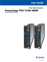
FOXBOX HDMI • Setup Guide
This guide provides quick start instructions for an experienced installer to set up and operate
the Extron FOXBOX HDMI fiber optic extenders.
CAUTION: These units output continuous invisible light, which may be harmful to
the eyes; use with caution. For additional safety, plug the attached dust
caps into the optical transceivers when the fiber optic cable is unplugged.
Installation
FOXBOX Tx HDMI Rear Panel
Front Panel
FOXBOX Rx HDMI Rear Panel
12V
1.0A MAX
POWER
FOXBOX Tx HDMI
AUDIO INPUT
RS-232
OVER FIBER
ALARM
Tx Rx 1 2
HDMI INPUT
LINK
OPTICAL
RxTx
LINK
FOXBOX Tx HDMI
AUDIO
HDCP
HDMI
CONFIG
HDMI LOOP THRU
EDID MINDER
50Hz
AUDIO
DIGITAL
ANALOG60Hz
1 2
12V
1.0A MAX
POWER
LINK
OPTICAL
RxTx
LINK
HDMI AUDIO
HDMI
AUDIO
OUTPUTS
OFF
ON
REMOTE
RS-232
Tx Rx
RS-232
OVER FIBER
ALARM
Tx Rx 1 2
LR
FOXBOX Rx HDMI
Step 1 — Mounting
Turn off or disconnect all equipment
power sources and mount the
transmitter and receiver as required.
Step 2 — Input and Output
Connections
a. Connect an HDMI video source to
the transmitter HDMI connector.
b. If desired, connect an HDMI video display to the transmitter HDMI Loop-Thru connector.
c. Connect an HDMI video display to the receiver HDMI Output connector.
NOTE: Use a LockIt™ Lacing Bracket to securely fasten an HDMI cable to each device as follows.
1. Plug the HDMI cable into the panel connection
3
3
1
2
4
5
2. Loosen the HDMI connection mounting screw from the panel enough to allow
the LockIt lacing bracket to be placed over it. The screw does not have to be
removed.
3. Place the LockIt lacing bracket on the screw and against the HDMI connector,
then tighten the screw to secure the bracket.
ATTENTION: Do not overtighten the HDMI connector mounting
screw. The shield it fastens to is very thin and can
easily be stripped.
4. Loosely place the included tie wrap around the HDMI connector and the LockIt
lacing bracket as shown.
5. While holding the connector securely against the lacing bracket, use pliers or
similar tools to tighten the tie wrap, then remove any excess length.
d. Connect an audio input device to the transmitter Input Audio 3.5 mm mini jack.
e. Connect an audio device to the receiver Audio captive
screw connector. See the drawing at right.
ATTENTION: For unbalanced audio, connect the sleeves to the ground contact. DO NOT connect the sleeves to
the negative (–) contacts.
f. If you want the FOXBOX HDMI units to pass serial data or control signals, such as for serial control of a
ALARM
Tx Rx 1 2
RS-232
OVER FIBER
projector, connect the master device to the transmitter and the slave device to the receiver via the left three poles
(Tx, Rx, and
_
) of the RS-232 Over Fiber/Alarm 5-pole captive screw connectors on both units.
NOTE: For RS-232 responses (from the receiver to the transmitter), you must install the Receiver-Tx-to-transmitter-Rx cable in
step 3b and leave the receiver in normal configuration (see “Return Link and Daisy Chain Modes“ on the next page).
g. For serial control of a unit, connect a host device, such as a computer, to one of the following ports on the unit to be controlled:
Transmitter or receiver Configuration port — A 2.5 mm mini jack. A TRS RS-232 cable is included with the transmitter.
CONFIG
Receiver Remote RS-232 port — Use the Remote RS-232 3-pole captive screw connector.
The protocol for both of these ports is as follows:
REMOTE
RS-232
Tx Rx
• 9600 baud • no parity • 8 data bits
• 1 stop bit • no flow control
AUDIO INPUT
HDMI INPUT
Do not tin the wires!
Unbalanced Stereo OutputBalanced Stereo Output
Tip
NO GROUND HERE
NO GROUND HERE
Tip
LR
Sleeves
Tip
Ring
Tip
Ring
LR
Sleeves

2
h. For remote monitoring of the status of the Rx optical link on either the transmitter or receiver, connect a locally
ALARM
Tx Rx 1 2
RS-232
OVER FIBER
constructed or obtained device to the two right Alarm poles of the RS-232 Over Fiber/Alarm 5-pole captive screw
connector on that unit. The unit shorts both poles together when no light is detected.
Step 3 — Throughput Connections
NOTES: • See the two fiber cable connection drawings below. You can connect the transmitter and one or more receivers in one
of three ways:
• One way (transmitter to receiver) only, perform step a.
• Two way (transmitter to receiver and return), perform steps a and b.
• One way (transmitter to receiver) with daisy chain (receiver to receiver), perform steps a and c.
• HDCP compliance requires both fiber cables.
a. Connect the fiber between the Tx port on the transmitter and the Rx port on the receiver.
b. If you want the receiver to return serial data (such as responses from a controlled device) to the transmitter,
connect a cable between the Tx port on the receiver and Rx port on the transmitter.
c. If you want a receiver to daisy-chain the optical signal to another receiver (up to 10 receivers in a daisy chain):
• Connect the receiver Tx fiber cable to the Rx port on another receiver.
• Set each receiver to daisy chain mode. See “Return Link and Daisy Chain Modes,” below.
Operation
After all receivers, the transmitter, and their connected devices
are powered up, the system is fully operational. If any problems
are encountered, verify that the cables are routed and connected
properly and that all display devices have identical resolutions and refresh rates. If problems persist,
call the Extron S3 Sales & Technical Support Hotline at the number that is closest to you.
Return Link and Daisy Chain Modes
The receiver can operate in one of two modes (or both modes can be disabled):
Return link mode — The receiver outputs data on its Tx connector for return to the transmitter.
Daisy chain mode — The receiver daisy-chains its Rx connector input through to its Tx connector output.
Use SIS commands to toggle between return disable, normal, daisy chain modes. Connect a PC to the receiver and issue the
following command: 66*0*n#, where n = 0 = disable, 1 = enable return link (default mode), and 2 = daisy chain enable.
NOTES: • Up to 10 receivers, each in daisy chain mode, can be connected in a daisy chain to a single transmitter.
• Daisy chain mode works with non-HDCP sources only.
HDMI Audio Switch
This switch mutes (Off position) and unmutes (On position) the embedded audio output on the HDMI output connector.
HDMI AUDIO
OFF
ON
The audio on the captive screw output always remains active regardless of the setting of this switch.
Indications
Tx Link and Rx Link LEDs — When lit, the link is active (light is output [Tx] or received [Rx]).
OPTICAL
Tx Rx
LINK
LINK
NOTE: The Link LEDs indicate transmission of light only, not whether there is data encoded in the optical link.
Power LED
— This LED lights to indicate that power is applied to the unit.
AUDIO
HDCP
HDMI
HDMI LED — This LED lights on both units when the transmitter detects a signal on its video input.
HDCP LED — This LED lights on both units when the input signal is HDCP encrypted.
Audio LED — This LED lights on both units when the transmitter detects a low level audio signal for a short period of time.
EDID
EDID Minder switch — Set this switch to one of the
positions at right to select the source of the DDC or a
specific resolution.
Position 0 — An EDID that has been captured
from the display connected to the transmitter
HDMI loop-thru connector.
Position 1 — The DDC is selected via a serial port on the Tx only using an SIS command or the FOX Extender Control Program.
Position 2 - F — Specify a resolution. The table identifies the switch positions and the associated resolutions.
68-1984-50
Rev A
05 12
Receiver
Transmitter
Tx Rx
Tx Rx
and
3a
3b
From Transmitter
or Daisy-Chained
Receiver
Receiver
Receiver
Tx Rx
Tx Rx
3a
3c
Pos. Source or resolution Pos. Resolution Pos. Resolution
0 User recorded EDID 6 1280 x 800 C 1600 x 1200
1 RS-232 7 1280 x 1024 D 1680 x 1050
2 800 x 600 8 1360 x 768 E 1920 x 1080
3 1024 x 768 9 1366 x 768 F 1920 x 1200
4 1280 x 720 A 1400 x 1050
5 1280 x 768 B 1440 x 900
© 2012 Extron Electronics. All rights reserved. www.extron.com
X2) = Rx link and daisy chain enable
2 = daisy chain enable
FOXBOX HDMI • Setup Guide (Continued)
/