Page is loading ...

TECHNICAL MANUAL
FOR
POT & PAN
WASHER
MODELS
CA-3
DA-3
CA-3C

TECHNICAL MANUAL
including Installation, Operation, and Maintenance Instructions
FOR
POT & PAN WASHERS
MODELS
CA-3
CA-3C
DA-3

POT and PAN WASHER
Models: CA-3/CA-3C/DA-3
Table of Contents
Part 1 - Technical Information
4 Introduction
4 Catalogue Cut-sheet and Installation Drawing
4 Warranty
4 Authorized Service Agency Network Listing
Part 2 - Installation and Operation Instructions
4 Section A, Installation Instructions
4 Section B, Operation and Cleaning Instructions
Part 3 - Maintenance and Repair Procedures
4 Section A, Maintenance and Repair Procedures
4 Basic Service Guide
Part 4 - Electrical Schematics and Electrical Replacement Parts
4 Machine Wiring Diagrams
4 Control Panel Layout and Component Drawing
Part 5 - Replacement Parts
4 Overall Assembly Drawing for:
4CA-3
4CA-3C
4DA-3
4 Drain Assembly
4 Discharge Line Assembly
4 Upper and Lower Manifold Assembly's
4 Spray Nozzle Assembly, wash
4 Spray Nozzle Assembly, rinse
4 Motor Assembly's
4 Door and Counter Balance Assembly
4 Level Float Installation
4 Final Rinse Piping Assembly
4 Utility Rack

POT & PAN WASHERS
MODEL: CA-3/CA-3C/DA-3
TECH MANUAL INTRODUCTION
Part 1, Section A
A. INTRODUCTION
A.1 Purpose
The purpose of this Tech Manual is to provide installation, operation, cleaning and
maintenance directions. A section is provided for replacement parts.
A.2 Scope
This manual contains all pertinent information to assist in the proper installation, operation,
cleaning, maintenance, and parts ordering for Insinger's Pot & Pan Washers model CA-3, CA-3C &
DA-3.
The installation instructions are intended for qualified equipment installers. The operation and
cleaning instructions are intended for the daily users of the equipment. The maintenance and parts
sections are intended for qualified service and/or maintenance technicians.
Replacement parts may be ordered directly from our factory or from your local Insinger Authorized
Service Agency. For the name of your local Insinger Authorized Service Agency please reference
the Service Network Listing in Section 1 of this manual. You can also speak to the Insinger
Technical Services Department, 800/344-4802, or e-mail us at [email protected].
When calling for warranty information or replacement parts please provide the model and serial
number of your Insinger equipment. These important numbers should be noted in this manual on
the spaces provided on the opening page.
A.3 Start-Up Program
Insinger is proud to offer our exclusive Surefire™ Start-up & Check-out Program to our commercial
customers. This service is included in the purchase price of your new Insinger dishwasher. We will
provide an authorized factory service technician for the initial start-up of your new Insinger
dishwasher to ensure it is running correctly. Please call the factory or your local Insinger Sales
Representative to schedule this service.
A.4 Definitions
Throughout this guide you will find the following terms: WARNING, CAUTION, & NOTE. When
used, these terms will be outlined in a box to draw attention:
WARNING indicates potential physical danger.
CAUTION indicates potential equipment damage.
NOTE indicates helpful operating hints or tips.

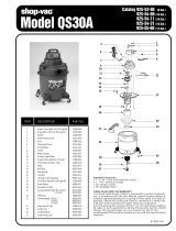
CA-3 and DA-3
POT AND PAN WASHERS
DESIGN
Automatic door type utensil washer with a
timed wash-and-rinse cycle. Fully
automatic operation with power on/off
button. CA-3 capacity is 25-24" x 28"
racks per hour, or 150 bun pans/hr or 100
steam table (2" thick) pans/hr. DA-3
capacity is 46 - 24" x 28" racks per hour,
or 276 bun pans/hr or 184 steam table
(2" thick) pans/hr. Cycle starts when doors
are closed. Designed for straight through
operation.
STANDARD EQUIPMENT
• Tank heat: 5 KW electric immersion
heater or steam injector
• Capillary Thermometer for Wash
• In-Line Thermometer tor Final Rinse
• Vacuum Breaker
• Rack Assortment (CA-31 General
Utility, 1 Bake Sheet, 1 Basket) (DA-3 2
General Utility. 2 Bake Sheet. 1 Basket,
1 Counter Pan)
• Manifold Cleanout Brush
• Inspection Door
• Vent opening with adjustable damper
(one for CA-3, two for DA-3)
• S/S frame with S/S Legs
• Automatic Tank fill
• Low Water Protection
• Detergent Connection Provision
• Hold down grid
• Rollers for Track on DA-3
• Fully Automatic Operation
• Manual Bypass Selector Switch
• Side Mounted Control Panel
(NEMA 12)
• Simplified Scrap Screen Design
• Door Safety Switch
• Interchangeable Upper & Lower Spray
Arms
• Standard Frame Drip Proof Motor
OPTIONAL ACCESSORY
EQUIPMENT
Stainless steel steam coil tank heat
Pressure Reduction Valve and Line
Strainer
Steam booster
Electric booster
Security package
S/S front panel
Totally Enclosed Motor
800/344-4802
NOTES:

SPECIFICATIONS Note: For all rough in connections see Installation and Layout Detail Drawing.
CONSTRUCTION—Hood and tank constructed of 14 gauge 18-8 type 304 S/S. Hood unit of all welded seamless
construction. S/S base frame and legs. All internal castings are non-corrosive lead free nickel alloy or bronze.
DOORS—a front inspection/cleanout door and two simultaneously opening operating doors. Operating doors balanced
by externally mounted springs. Extra large die formed 18-8 type 304 S/S doors ride in all S/S channels. A triple ply
leading edge on the door channels made of S/S.
PUMP—Centrifugal type "packless" pump with a brass petcock drain. Construction includes ceramic seal and a
balanced cast impeller on a precision ground stainless steel shaft. All working parts mounted as an assembly and
removable as a unit without disturbing pump housing. CA-3 has one 5 HP motor. DA-3 has two 5 HP motors. Motors
are standard frame, horizontal C-faced, drip proof, squirrel-cage, induction run type, 60 cycle, 3600 RPM, internally
cooled with ball-bearing construction.
CONTROLS—Side mounted control cabinet, NEMA 12 rated housing motor controls and overload protection,
transformer, contactors and all dishwasher integral controls. All controls safe low voltage 24 VAC.
SPRAY SYSTEM—Wash and rinse spray systems made of 18-8 type 304 S/S schedule 40 pipe threaded into cast
hub assemblies. Upper and lower spray assemblies are interchangeable and are removable without the use of tools.
CA-3 Wash-2 power spinning wash arms above and 2 power spinning wash arms below each designed with 8 high
pressure action cleansing boles.
Final Rinse-2 power spinning rinse arms above and 2 power spinning rinse arms below each designed with 3 nozzles.
DA-3 Wash -4 power spinning wash arms above and 4 power spinning wash arms below each designed with 8 high
pressure action cleansing hole.
Final Rinse-4 power spinning rinse arms above and 4 power spinning rinse arms below each designed with 3 nozzles.
DRAIN—Drain valves externally controlled. Overflow assemblies with skimmer caps are removable without use of
tools for drain line inspection. Heaters protected by low water level control.
Capacity
per hour
CA3-25 racks
DA3-46 racks
Tank capacity
CA3-30 gals.
DA3-60 gals.
Motor size
CA3-5 hp
DA3-(2) 5 hp
Electric usage
CA3 DA3
5 5 kw wash tank
9 18 kw booster 40°
rise
17 36 kw booster 70° rise
Steam consumption
at 20 psi min.
CA3-20lbs./hr. tank
DA3-20lbs./hr. tank
Final rinse peak flow
at 20 psi min.
CA3-16 gals./min.
DA3 - 29.8 gals./min.
Current draw Steam Electric
amps CA3 DA3 CA3 DA3
208/3/60..............16.....33..........…30.....46
230/1/60.............. n/a....n/a...........n/a....n/a
230/3/60...........….15.....30............27.....42
380/3/60...........….10.....20............17.....27
460/3/60...........…..7......15............14.....21
Final rinse consumption at
20 psi min.
CA3 -100 gals./rack / 5 gals./hr.
DA3 - 183 gals./rack / 4 gals./hr.
Exhaust hood
requirement
CA3-300 CFM
DA3-600 CFM
Peak rate
drain flow
CA3 - 9 gals./min.
DA3-16gals./min.
Shipping
weight
CA3-1050 lbs.
DA3-1650 lbs.


POT and PAN WASHER
MODEL: CA-3/CA-3C/DA-3
INSTALLATION INSTRUCTIONS
Part 2, Section A
2.A.1 PLACEMENT
2.A.1.1 Carefully uncrate machine. Take caution to not damage components which
may be mounted on the top or sides of the machine.
2.A.1.2 Set unit in place and adjust the feet to level the machine.
2.A.1.3 Fasten the tables to the load and unload side of the machine. Most
installations require fastening the turn-down lip of the dish tables to the side of the
machine with flathead counter-sunk screws. The table design should provide horizontal
clearance of 30" for servicing.
2.A.2 ELECTRICAL CONNECTIONS
2.A.2.1 Connect electrical lines sized for the correct voltage, current and phase of the machine.
These should agree with machine requirements indicated on the nameplate and labels in control
panel. This Fuse Sizing Chart should be used as a guide for proper line protection:
Caution
Connections must be made to a circuit breaker or fused disconnect
as provided by the end-user and required by local codes. A laminated
wiring diagram is inside the control panel
Fuse Sizing Chart
Model
208VAC/3Θ 230VAC/3Θ 380VAC/3Θ 460VAC/3Θ
CA-3(C)
steam heat
25A 20A 15A 10A
CA-3(C)
electric heat
35A 35A 20A 20A
CA-3(C)
gas heat
25A 20A 15A 10A
DA-3
steam heat
40A 35A 25A 20A
DA-3
electric heat
60A 50A 30A 25A

POT and PAN WASHER
MODEL: CA-3/CA-3C/DA-3
INSTALLATION INSTRUCTIONS
Part 2, Section A
2.A.2.2 On machines not provided with a single-point connection there is an electrical connection
required for the, 1. Pumps and control circuit, and Wash tank heater.
2.A.2.3 If an electrical booster is provided connect the power directly to the booster.
Caution
As with any 3 phase system, an electrician must check all motors for proper
phasing, i.e., Pump motors must be running in direction
indicated by arrow on housing.
2.A.3 MECHANICAL CONNECTIONS
2.A.3.1 Connect 140°F water lines for tank fills/booster as tagged and noted on the
installation drawings.
2.A.3.2 If machine is provided with steam heat connect the steam lines and steam
condensate lines as tagged and noted on installation drawings.
2.A.3.3 Connect the drain line.
Caution
Drain lines must be as specified on installation drawings. Drain line should
be properly vented and should have fall of not less than 1/4" to the foot of
proper flow. Some area plumbing codes require drains to flow into an open
gap with an opening twice the diameter of the pipe. Check with your local
plumbing codes for the type of drain connection required.
Caution
All lines must be flushed prior to use to remove debris.
Caution
Do not reduce the size of lines as specified in installation drawings. All
lines are sized to facilitate necessary flows, pressures, etc.

POT and PAN WASHER
MODEL: CA-3/CA-3C/DA-3
INSTALLATION INSTRUCTIONS
Part 2, Section A
2.A.4 HVAC
2.A.4.1 Ventilation system should be sized to provide adequate ventilation per machine specs.
Refer to spec sheet.
2.A.5 CHEMICALS
2.A.5.1 Upon completed installation of the dishwasher contact a local detergent/chemical supplier
for the correct chemicals for your area.
2.A.5.2 Electrical connection points for the detergent dispenser and rinse injector are located
inside the control panel. Refer to the wiring diagram for this machine for the proper connection
points. Dispensers may be connected on either the primary voltage side of the machine or the
24VAC control voltage side.
Caution
When connecting on the 24VAC control voltage side of the
transformer, total VA must not exceed 50VA.
2.A.5.3 The detergent density probe should be installed in the hole provided & labelled in the wash
tank.
2.A.5.4 The switch on the control panel labelled "Manual" and the switch labelled "Wash" may be
used when de-liming the machine. When activated, these switches keep the machine in an
indefinite wash cycle. This feature can also be used to wash heavily soiled ware.
2.A.6 Tabling
2.A.6.1 Load and unload tables should be pitched towards the machine to return excess water
into the machine.

POT and PAN WASHER
MODEL: CA-3/CA-3C/DA-3
OPERATION & CLEANING INSTRUCTIONS
Part 2, Section B
Insinger dishmachines are user-friendly, making them the easiest dishwashers to operate and maintain.
By following the operation procedure and general cleaning procedures your Insinger dishwasher will give
you years of trouble free service.
2.B.1 Operation Instructions
2.B.1.1 Ensure drain overflow tube is in place Close the tank drain valve.
2.B.1.2 Check for proper installation and cleanliness of all internal, removable
components such as suction strainers, scrap screens, and rotating spray pipes.
2.B.1.3 Ensure all water, and steam, lines are open. Ensure electrical circuits are on.
2.B.1.4 Close machine doors.
2.B.1.5 Move the power toggle switch to the "ON" position. The machine will fill the
tank, run through a complete wash/rinse cycle and shut-off.
2.B.1.6 When the tank is full the tank heat will operate automatically. Proper tank heat
is 150°F.
Caution
To ensure proper operation of the auto tank fill feature and the tank
heaters, level float(s) located in each tank MUST be cleaned daily
2.B.1.7 Open doors.
2.B.1.8 Insert a rack of soiled dishware in machine (two racks for the DA-3) and lower doors.
Machine will wash and rinse automatically. When the rinse indicator light goes off the cycle is
complete.
Note
Overloading racks will minimize the proper cleaning of ware.
Warning
Do not open the doors during the wash/rinse cycle as hot water is being
sprayed. An interlock is provided to stop the wash/rinse cycle if the doors
are opened but the momentum of the spinning hubs will cause hot water to
be sprayed.

POT and PAN WASHER
MODEL: CA-3/CA-3C/DA-3
OPERATION & CLEANING INSTRUCTIONS
Part 2, Section B
2.B.1.9 Raise doors and remove rack of clean ware. For continuous operation repeat
steps B.1.9 and B.1.10.
2.B.1.10 Upon completion of ware cleaning move the power toggle switch to the "OFF"
position.
2.B.1.11 Refer to the cleaning procedures for proper clean-up of the dishmachine.
2.B.1.12 Report any unusual occurrences to qualified service personnel.
The following cleaning procedures should be done daily, at the end of the shift.
2.B.2 Cleaning Procedures, Daily
2.B.2.1 Remove all internal removeable parts including rotating spray pipes, scrap screens, drain
overflow tubes, suction strainers and curtains.
2.B.2.2 Remove the end caps from the spray manifolds and clean with the brush provided. Flush
the manifolds.
Note
Do not remove wash and rinse spray arms from the hubs as these
are factory set. Cleaning should be done by removing the endcap on
each arm.
2.B.2.3 Flush scrap screens.
2.B.2.4 Clean drain overflow tube.
Note
V-cup seal on the drain overflow tube may become gummed and not
allow the overflow tube to seat properly. This will cause the drain to leak
water. Remove any build-up on the v-seal. When the seal becomes worn,
replace.
2.B.2.5 Clean suction strainers of build-up.
Note
Improper cleaning of suction strainers will cause the pumps to cavitate.
This will cause poor washing results.

POT and PAN WASHER
MODEL: CA-3/CA-3C/DA-3
MAINTENANCE & REPAIR PROCEDURES
Part 3, Section A
Following is a basic guide for the repair and replacement of common dishwasher parts. Refer to the
Basic Service Guide for troubleshooting tips.
3.A.1 MAINTENANCE
3.A.1.1 Daily - Refer to the operation and cleaning instructions provided in this manual for
daily cleaning procedures.
3.A.1.2 Weekly
3.A.1.2.1 The entire machine should be wiped down using an industrial
grade stainless steel cleaner.
3.A.1.2.2 Under the supervision of your detergent supplier the machine
interior must be properly de-limed.
Note
The water quality in some areas requires de-liming to be done more
frequently. Contact your detergent supplier for recommended de-
liming frequency.
3.A.1.3 Quarterly
3.A.1.3.1 Remove and clean the strainer screens on water and steam lines. If
the screens cannot be cleaned, replace.
3.A.1.3.2 Inspect condition of solenoid valve seats and diaphragms. Replace
where necessary.
3.A.1.3.3 Inspect drain O-Rings for leakage. Replace where necessary.
3.A.1.3.4 Check door spring tension and adjust where necessary.
3.A.1.3.5 Check wash and rinse hub bushing/bearing and replace where
necessary.
3.A.2 MAINTENANCE PROCEDURES
3.A.2.1 Solenoid Valve Disassembly
3.A.2.1.1 Disconnect power supply to machine. Turn off Water supply.
3.A.2.1.2 Remove cap on top of coil. Remove coil.
3.A.2.1.3 Remove 4 hex bolts and lift bonnet from valve body. Note positioning
of spring and plunger.
3.A.2.1.4 Remove main piston.
3.A.2.1.5 Inspect for dirt, wear or lime build-up. Clean or replace as required.
3.A.2.1.6 Reassemble in reverse of disassembly.

POT and PAN WASHER
MODEL: CA-3/CA-3C/DA-3
MAINTENANCE & REPAIR PROCEDURES
Part 3, Section A
3.A.2.2 Line Strainer Disassembly
3.A.2.2.1 Shut off water or steam supply.
3.A.2.2.2 Remove large hex nut on bottom of strainer body.
3.A.2.2.3 Remove strainer screen. Inspect and clean or replace as necessary.
3.A.2.2.4 Reassemble in reverse of disassembly. Water flow must be same
direction as arrow on line strainer body. Use new gaskets to insure a tight seal.
3.A.2.3 Pump Disassembly
3.A.2.3.1 Before disassembling pump ensure there are no obstructions in the pump intake.
Remove and clean the suction strainer (inside tank).
Note
It is not necessary to remove the pump housing from the machine
to disassemble the pump.
3.A.2.3.2 Remove the pump motor and impeller adaptor by removing the 4 hex
bolts attaching them to the pump housing.
3.A.2.3.3 Repair or replace the pump parts as required.
3.A.2.3.4 Reassemble in reverse of disassembly.
3.A.2.4 Immersion Heater Replacement
Note
Immersion heaters MUST be completely submerged at all times. Running
the heaters in air will cause the heater to prematurely fail
3.A.2.4.1 Remove the housing covering the wiring terminations. Disconnect the immersion
heater wires.
3.A.2.4.2 Remove the immersion heater by loosening and removing the large hex nut..

POT and PAN WASHER
MODEL: CA-3/CA-3C/DA-3
MAINTENANCE & REPAIR PROCEDURES
Part 3, Section A
3.A.2.4.3 Install in reverse of removal.
Note
To reduce the possiblity of leaking, use plumbers putty on the
immersion heater nuts.
3.A.2.5 Wash Tank Temperature Adjustment
3.A.2.5.1 A temperature control board is provided in the control panel for easy
adjustment of tank temperature. Though tank temperature is adjusted during the
machines factory test it is sometimes necessary to re-adjust the temperature.
3.A.2.5.2 Locate the temperature control board (P/N DE9-96). Use the control
panel layout drawing located in Part 4, Electrical Schematic and Replacement
Parts.
3.A.2.5.3 Adjust the tank temperature to the desired temperature by turning the
potentiometer located on the temperature control board. An arrow on the
potentiometer indicates increase.
3.A.2.5.4 If the temperature does not change refer to section A.2.6,
Troubleshooting Tank Temperatures.
3.A.2.6 Troubleshooting Tank Temperatures
3.A.2.6.1 Electric Heat
3.A.2.6.1.1 If temperature cannot be adjusted per section A.2.5 check the
temperature control board P/N DE9-96 proper operation. If the temperature
control board is faulty, replace.
3.A.2.6.1.2 Verify tank heat contactor is working correctly. If not, replace.
3.A.2.6.1.3 Verify all immersion heaters are working properly and not limed. If
not, replace.
3.A.2.6.2 Steam Heat
3.A.2.6.2.1 See Section A.2.6.1.1.
3.A.2.6.2.2 Verify steam pressure per machine specifications.
3.A.2.6.2.3 Verify steam trap is not clogged. IF so, clean or replace.
3.A.2.6.2.4 Verify proper operation of steam solenoid. If not, replace.
3.A.2.6.3 Gas Heat
3.A.2.6.3.1 See Section A.2.6.1.1.
3.A.2.6.3.2 Verify gas supply.
3.A.2.6.3.3 Verify pilot is lit. If not, light. If pilot does not stay lit, replace.
3.A.2.6.3.4 Verify gas solenoid is working correctly. If not, replace.

POT and PAN WASHER
MODEL: CA-3/CA-3C/DA-3
MAINTENANCE & REPAIR PROCEDURES
Part 3, Section A
3.A.2.7 Motor Overloads
3.A.2.7.1 All motors used on Insinger Machines are provided with motor overloads. Motor
overloads are adjusted when the machines are factory tested. Should it be necessary to
adjust the motor overloads first verify the motor current draw for the voltage the machine is
using.
3.A.2.7.2 Using the Control Panel Component Layout Drawing located in Section 4 to
identify the overload, adjust by turning the dial to the appropriate current draw.
3.A.2.8 Level System
3.A.2.8.1 The level control system consists of one timer (P/N DE7-31) and two
level floats (P/N DE5-60) per tank.
3.A.2.8.2 The level timer will not allow the tank heat to energize without water in
the tank.
3.A.2.8.3 Should the tank heat energize with out water in the tank troubleshoot
the system to find the problem.
Caution
Dirty level floats may cause the tank heat to energize with no water in the
tanks. LEVEL FLOATS MUST BE CLEANED DAILY.
3.A.2.9 Wash and Rinse Cycle
3.A.2.9.1 The timing sequence consists of two timers. The CA-3, CA-3C, and DA-3 use 1,
five minute timer adjusted to 120 seconds for the wash cycle (P/N DE7-28)and 1, one
minute timer adjusted to 15 seconds (P/N DE7-27). Should either of these become
defective, replace.

BASIC SERVICE GUIDE
SYMPTOM POSSIBLE CAUSE Solution
a. No Power a. Check power supply
b. Blown fuse or tripped breaker b. Replace fuse; reset breaker
1. Machine will not operate
c. Motor overloads tripped c. Reset overload
a. Drain not closed a. Close drain
b. Drain overflow not seated or installed
b. Reseat or install drain overflow
2. Tank will not hold water
c. Pump petcock opened c. Replace V-seal
3. Tank fills beyond overflow a. Obstruction in overflow tube or drain
line
a. Remove obstruction
a. Doors not seating a. Reseat doors 4. Water leaks around door
b. Clogged spray pipe b. Clean spray pipe with brush provided
a. Clogged spray pipe a. Clean spray pipe with brush pipe
b. Manifolds not installed properly b. Ensure proper placement of upper
and lower pipes
c. Obstruction in pump c. Clear obstruction through pump
inspection plate
d. Pump rotation reversed d. Arrow on pump housing indicates
direction, correct electrically
5. Weak or ineffective spray
e. Suction strainer clogged e. Clean suction strainer

BASIC SERVICE GUIDE
SYMPTOM POSSIBLE CAUSE Solution
a. Lime deposits in spray nozzles a. Clean or replace nozzles
b. Low water pressure b. Adjust to 20 PSI
c. Clogged line strainer c. Remove line strainer and
clean
6. Weak or ineffective final rinse
spray
d. Closed water supply valve d. Open ball valve
7. Water hammer a. Excessive water line pressure a. Install water hammer limiting
device
a. Pump rotation reversed a. Arrow on pump housing
indicates direction, correct
electrically
8. Machine vibrates or is noisy
b. Pump bearings worn b. Replace pump bearings
a. Final rinse solenoid valve
clogged
a. Disassemble valve and clean
internal parts of scale or
replace
b. Diaphragm worn b. Replace with solenoid valve
repair kit
9. Final rinse will not shut off
c. Solenoid valve still powered-up c. Check final rinse actuating
circuit for proper operation
/