V-ZUG 31062 Installation guide

Category
Cookers
Type
Installation guide

This manual is also suitable for

V-ZUG 31062 induction hob offers a unique cooking experience with its advanced features and intuitive controls. With its flexible cooking zones, you can adjust the size and shape to fit your cookware, ensuring even heat distribution for perfect results. The hob's power boost function provides a quick burst of heat for faster boiling and searing, saving you time in the kitchen. The sleek and modern design of the V-ZUG 31062 complements any kitchen décor, making it a stylish and functional addition to your home.

V-ZUG 31062 induction hob offers a unique cooking experience with its advanced features and intuitive controls. With its flexible cooking zones, you can adjust the size and shape to fit your cookware, ensuring even heat distribution for perfect results. The hob's power boost function provides a quick burst of heat for faster boiling and searing, saving you time in the kitchen. The sleek and modern design of the V-ZUG 31062 complements any kitchen décor, making it a stylish and functional addition to your home.

Installation instructions
Induction hob
GK11TIFKZ | GK11TIFKZS | CTI6T96FKTFHD
1032691-R08
28/02/2020
1032691-R08
1
The appliance should be installed by qualified personnel only. Each step must be carried out and checked in full in
the order specified.
Validity
These installation instructions apply to the following models:
Model designation Model number Type Frameless,
for surface-mounted installa-
tion
Frameless,
for flush installation
GK11TIFK FullFlex 31062 GK11TIFKZ GK11TIFKZ GK11TIFKZ
GK11TIFK FullFlex 31062 GK11TIFKZS GK11TIFKZS GK11TIFKZS
CookTopInduktion V6000 FullFlex 31134 CTI6T-31134 CTI6T96FKTFHD CTI6T96FKTFHD
General notes
If installing into a combustible material, the guidelines and standards for low-voltage installations and fire protection
must be strictly observed.
Identification plate
1
1 Identification plate with serial number (SN)
Affix the second identification plate (supplied) in an accessible position behind the front of the fitted cabinet beneath the appliance.
Installation accessories supplied
Flush installation:
Designation Art. no.
Cementing-in instructions J004133
Sealing strip set H63283
Spacer set H60330
Accessories
Flush installation:
Designation Art. no.
Ventilation protective plate set for niche width 900mm H61089
Steel angle set, installation dimension 90 H63775
Intermediate support kit for the flush-mounted combination of several hobs (contains two intermediate supports) H63789
Instant adhesive for installation of the steel angle (50ml) B11657
Straight mixing nozzle B11656
TREMCLEAN isopropyl alcohol (1000ml) 1056609
Black silicone FA880 (310ml) B11555
Anthracite silicone FA880 (310ml) B11556
White silicone FA880 (310ml) 1031313
Stone grey silicone FA880 (310ml) 1031314
Marble smoothing agent AA320 (1000ml) B11557
Fugenboy (silicone finishing tool) B75158
Installation instructions
Induction hob
GK11TIFKZ | GK11TIFKZS | CTI6T96FKTFHD
1032691-R08
28/02/2020
1032691-R08
2
Ventilation
In order to guarantee good ventilation, a space of ≥10mm
height is necessary beneath the appliance.
1. The rear panel of the base unit must be open around the
worktop cut-out to guarantee continuous air circulation via
the ventilation slits.
The air must be drawn in from outside the cabinet and be
able to circulate freely from inside the cabinet to the hob.
2. Alternatively, a concealed fresh air supply can ensure air
circulation inside the cabinet.
In order that enough cold air can be drawn in, there must
be a continuous circulation of fresh air that extends outside
the cabinet.
The air must be drawn in from outside the cabinet and be
able to circulate freely from inside the cabinet to the hob.
≥15
21
≥3
Installation instructions
Induction hob
GK11TIFKZ | GK11TIFKZS | CTI6T96FKTFHD
1032691-R08
28/02/2020
1032691-R08
3
Electrical connection
Electrical connections must be carried out by qualified personnel in accordance with the guidelines and standards
for low-voltage installations and the specifications of the local electricity supply companies.
Refer to the identification plate for information on the required mains voltage and current type.
A plug-in appliance may only be connected to a socket outlet with earthing contact, installed according to specifications. An
all-pole mains isolating device with 3 mm contact opening should be provided in the house wiring system. Switches, plug and
socket devices, circuit breakers and fusible cut-outs which are accessible after installation and which have all-poles switching
are permissible as isolating devices. Effective earthing and separately installed neutral and earth conductors ensure safe and
fault-free operation. After installation, live parts and cables with basic insulation must not be accessible. Check old installa-
tions.
If the hobs are used at an altitude of over 2,000metres,a reduced performance must be expected.
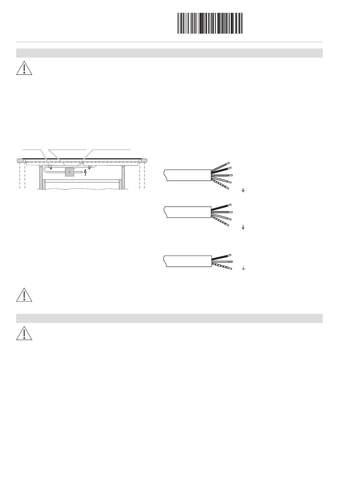
The appliance is equipped with a connection cable which must be connected to an on-site junction box.
Installation pipe Distribution boxClamp
brown
blue
yellow/green
grey
blue
yellow/green
brown
L3
L1
N
N
L1
PE/
PE/
black
L2
400 V 3N~ / 16 A
230 V~ / 48 A
blue
yellow/green
brown
L1
N
PE/
black
L2
400 V 2N~ / 16 A
3106200.../3106203.../3106260.../3106266...
3113400001–3113400003
3106261.../3106265.../3106267...
3113400004
E35/U0 error message
Incorrect connection:
Pole conductor connected to connection terminal for neutral conductor.
Quickly disconnect the appliance from the mains!
General information about installation
The distance from the appliance cut-out to flammable walls (left, right and rear) must be ≥50mm. Parts such as side
walls and reinforcing strips which protrude into the installation space under the cooking zone must be made of non-
combustible materials.
It is recommended that a distance of 20mm be maintained between the underside of the appliance tray and any part
of the cabinet beneath that is made of combustible material. If a drawer is installed directly underneath – and if the
tray can be reached from below without the aid of tools – touch protection must be used. The ventilation protective
plate set (see Accessories) is recommended for this purpose.
The worktop must be flat so that it is sufficiently sealed against the ingress of liquids.
In order to guarantee good ventilation, a space of at least 10mm in height is necessary beneath the appliance.
A cabinet element with a width of 900mm is recommended for the base element.
Installation instructions
Induction hob
GK11TIFKZ | GK11TIFKZS | CTI6T96FKTFHD
1032691-R08
28/02/2020
1032691-R08
4
Overlying installation
The layout of the hob to be fitted may differ from the hob illustrated!
2×881
2×498
900
A
886±1
≥50
490±1
≥50
B
8
25
=
=
≥490
2
501
8
97
H
Y
Y
Ri
Ra
≥10 *
B
Drawer/Cabinet
Air inlet
H
Y – Y
* The required clearance must be observed!
2 The front and rear pegs are reinforced underneath. The strut width is determined by the producer of the stone worktop. The
minimum peg width can vary according to the properties of the stone.
Type designation A Depends on producer B H Corner radius Ra/Ri
GK11TIFKZ, GK11TIFKZS
CTI6T96FKTFHD
≥40mm ≥82mm 72mm 5/1.5mm
A Worktop depth
B Required clearance for service replacement over the entire cut-out area.
H Dimension from the top of the work surface to the underside of the hob
Ri Corner radii of appliance Ra Outer corner radii of cut-out
Installation
1. Create an accurate installation cut-out.
2. Stick the sealing tape to the underside of the glass.
3. Carefully put the appliance in the installation cut-out and press against the worktop with sufficient overlap.
Installation instructions
Induction hob
GK11TIFKZ | GK11TIFKZS | CTI6T96FKTFHD
1032691-R08
28/02/2020
1032691-R08
5
Flush installation
The layout of the hob to be fitted may differ from the hob illustrated!
886
4
90
Ra
R0–5
8.5
0
-1
8.5
0
-0.5
8.5
8.5
+1
0
+1
0
Detail Z
Steel angle bonded
or screw mounted
501
8
97
H
90
0
A
600
903±1
507±1
Y
Y
B
825
=
=
2
Ri
≥50
≥50
≥507
Z
H
Y – Y
B
Drawer/Cabinet
Side panel
Air inlet
≥10 *
* The required clearance must be observed!
2 The front and rear pegs are reinforced underneath. The strut width is determined by the producer of the stone worktop. The
minimum peg width can vary according to the properties of the stone.
Type designation A Depends on producer B H Corner radius Ra/Ri
GK11TIFKZ, GK11TIFKZS
CTI6T96FKTFHD
≥40mm ≥150mm 76mm 5/1.5mm
A Worktop depth
B Required clearance for service replacement over the entire cut-out area.
H Dimension from the top of the work surface to the underside of the hob
Ri Corner radii of appliance Ra Outer corner radii of cut-out
Installation
1. Create an accurate installation cut-out.
The mounting surface can be reamed out or created by installing wood/stone supports or using the steel angle set (see Accessor-
ies).
Access to the appliance from below via the entire cut-out area must be guaranteed. For servicing purposes, the induction gen-
erator can be removed from below with the mounting plate. It must be possible to unscrew the contact-proof covers from be-
low.
2. Prepare the cut-out and appliance in accordance with the specifications in the enclosed cementing-in instructions.
3. Carefully cement the appliance in and leave the silicone sealant to dry for at least 24 hours.
4. Connect to the electrical mains connection before inserting the appliance, if necessary.
Installation instructions
Induction hob
GK11TIFKZ | GK11TIFKZS | CTI6T96FKTFHD
1032691-R08
28/02/2020
1032691-R08
6
Cool air supply with regard to drawer or cabinet installed below
A gap of ≥10mm in height is required beneath the appliance.
≥5
≥15
900/825
≥25 cm²
H
Drawer
Air gap over the entire cabinet element width
A
A Necessary space below the worktop for the appliance.
H Dimension from the top of the work surface to the underside of the hob (ventilation opening)
Installation of the ventilation protective plate with 3 mm ventilation gap at the front
A protective plate is necessary for the adequate ventilation of the hob.
The distance X between the underside of the appliance and the protective plate must be ≥10mm.
Type designation X H Remarks
GK11TIFKZ, GK11TIFKZS, CTI6T96FKTFHD 14mm 72mm Surface-mounted installation
GK11TIFKZ, GK11TIFKZS, CTI6T96FKTFHD 10mm 76mm Flush installation
H Dimension from the top of the work surface to the underside of the hob (ventilation opening).
  • Page 1 1
  • Page 2 2
  • Page 3 3
  • Page 4 4
  • Page 5 5
  • Page 6 6

V-ZUG 31062 Installation guide

Category
Cookers
Type
Installation guide
This manual is also suitable for

V-ZUG 31062 induction hob offers a unique cooking experience with its advanced features and intuitive controls. With its flexible cooking zones, you can adjust the size and shape to fit your cookware, ensuring even heat distribution for perfect results. The hob's power boost function provides a quick burst of heat for faster boiling and searing, saving you time in the kitchen. The sleek and modern design of the V-ZUG 31062 complements any kitchen décor, making it a stylish and functional addition to your home.

Ask a question and I''ll find the answer in the document

Finding information in a document is now easier with AI