En-1
1. SAFETY PRECAUTIONS
Be sure to read this manual carefully before installation.•
The warnings and precautions indicated in this manual contain important information •
pertaining to your safety. Be sure to observe them.
Hand this manual, together with the operating manual, to the customer. Request the •
customer to keep them on hand for future use, such as for relocating or repairing the
unit.
WARNING
This mark indicates procedures which, if improperly performed,
might lead to the death or serious injury of the user.
CAUTION
This mark indicates procedures which, if improperly performed, might
possibly result in personal harm to the user, or damage to property.
WARNING
Never touch electrical components immediately after the power supply has been turned
off. Electrical shock may occur. After turning off the power, always wait 10 minutes or
more before touching electrical components.
Request your dealer or a professional installer to install the outdoor unit in accordance
with this installation manual. an improperly installed unit can cause serious accidents
such as water leakage, electric shock, or fi re.
If the outdoor unit is installed in disregard of the instructions in the installation manual, it
will void the manufacturer’s warranty.
Do not turn ON the power until all work has been completed. Turning ON the power
before the work is completed can cause serious accidents such as electric shock or fi re.
If refrigerant leaks while work is being carried out, ventilate the area. If the refrigerant
comes in contact with a fl ame, it produces a toxic gas.
Installation work must be performed in accordance with national wiring standards by
authorized personnel only.
Do not use this equipment with air or any other unspecifi ed refrigerant in the refrigerant
lines.
Excess pressure can cause a rupture.
During installation, make sure that the refrigerant pipe is attached fi rmly before you
run the compressor. Do not operate the compressor under the condition of refrigerant
piping not attached properly with 2-way or 3-way valve open. This may cause abnormal
pressure in the refrigeration cycle that leads to rupture and even injury.
When installing and relocating the air conditioner, do not mix gases other than the
specifi ed refrigerant (R410A) to enter the refrigerant cycle.
If air or other gas enters the refrigerant cycle, the pressure inside the cycle will rise to
an abnormally high value and cause rupture, injury, etc.
For the air conditioner to operate satisfactorily, install it as outlined in this installation
manual.
Connect the indoor unit and outdoor unit with the air conditioner piping and cable
available standards parts.
This installation manual describes the correct connections using the installation set
available from our standard parts.
Also, do not use an extension cable.
Do not purge the air with refrigerants but use a vacuum pump to vacuum the installation.
There is not extra refrigerant in the outdoor unit for air purging.
Using the same vacuum pump for different refrigerants may damage the vacuum pump
or the unit.
Use a clean gauge manifold, vacuum pump and charging hose for R410A exclusively.
During the pump-down operation, make sure that the compressor is turned off before
you remove the refrigerant piping.
Do not remove the connection pipe while the compressor is in operation with 2 way or 3
way valve open. This may cause abnormal pressure in the refrigeration cycle that leads
to rupture and even injury.
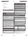
Contents
1. SAFETY PRECAUTIONS .......................................................................................... 1
2. ABOUT THE UNIT ..................................................................................................... 1
3. SELECTING THE MOUNTING POSITION ............................................................... 2
4. INSTALLATION DIAGRAM ........................................................................................ 2
5. INSTALLATION ......................................................................................................... 3
6. PUMP DOWN ............................................................................................................ 4
CAUTION
Read carefully all security information before use or install the air conditioner.
Do not attempt to install the air conditioner or a part of the air conditioner by yourself.
This unit must be installed by qualifi ed personnel with a capacity certifi cate for handling
refrigerant fl uids. Refer to regulation and laws in use on installation place.
The installation must be carried out in compliance with regulations in force in the place
of installation and the installation instructions of the manufacturer.
This unit is part of a set constituting an air conditioner. It must not be installed alone or
with non-authorized by the manufacturer.
The unit must be correctly earthed (grounded) and the supply line must be equipped
with a differential breaker in order to protect the persons.
The units are not explosion proof and therefore should not be installed in explosive atmosphere.
This unit contains no user-serviceable parts. Always consult authorized service
personnel to repairs.
When moving, consult authorized service personnel for disconnection and installation of
the unit.
Children should be monitored to ensure they do not play with the device.
This appliance is not intended for use by persons (including children) with reduced
physical, sensory or mental capabilities, or lack of experience and knowledge, unless
they have been given supervision or instruction concerning use of the appliance by a
person responsible for their safety. Children should be supervised to ensure that they do
not play with the appliance.
Do not touch the aluminum fi ns of heat exchanger built-in the indoor or outdoor unit to
avoid personal injury when you install or maintain the unit.
Do not place any other electrical products or household belongings under indoor unit or
outdoor unit. Dripping condensation from the unit might get them wet, and may cause
damage or malfunction of your property.
2. ABOUT THE UNIT
2.1. Precautions for using R410A refrigerant
WARNING
The basic installation work procedures are the same as conventional refrigerant (R22)
models.
However, pay careful attention to the following points:
Since the working pressure is 1.6 times higher than that of conventional refrigerant
(R22) models, some of the piping and installation and service tools are special. (See
the table below.)
Especially, when replacing a conventional refrigerant (R22) model with a new refrigerant
R410A model, always replace the conventional piping and flare nuts with the R410A piping
and fl are nuts.
Models that use refrigerant R410A have a different charging port thread diameter to pre-
vent erroneous charging with conventional refrigerant (R22) and for safety. Therefore,
check beforehand. [The charging port thread diameter for R410A is 1/2 inch.]
Be more careful that foreign matter (oil, water, etc.) does not enter the piping than with
refrigerant (R22) models. Also, when storing the piping, securely seal the opening by
pinching, taping, etc.
When charging the refrigerant, take into account the slight change in the composition of
the gas and liquid phases. And always charge from the liquid phase where refrigerant
composition is stable.
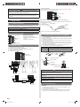
2.2. Special tools for R410A
Tool name Contents of change
Gauge manifold
Pressure is high and cannot be measured with a conven-
tional (R22) gauge. To prevent erroneous mixing of other
refrigerants, the diameter of each port has been changed.
It is recommended the gauge with seals -0.1 to 5.3 MPa
(-1 to 53 bar) for high pressure.
-0.1 to 3.8 MPa (-1 to 38 bar) for low pressure.
Charge hose
To increase pressure resistance, the hose material and base
size were changed.
Vacuum pump
A conventional vacuum pump can be used by installing a
vacuum pump adapter.
Gas leakage detector Special gas leakage detector for HFC refrigerant R410A.
Copper pipes
It is necessary to use seamless copper pipes and it is desirable that the amount of residual
oil is less than 40 mg/10 m. Do not use copper pipes having a collapsed, deformed or
discolored portion (especially on the interior surface). Otherwise, the expansion value or
capillary tube may become blocked with contaminants.
As an air conditioner using R410A incurs pressure higher than when using R22, it is neces-
sary to choose adequate materials.
Thicknesses of copper pipes used with R410A are as shown in Table1. Never use copper
pipes thinner than 0.8 mm even when it is available on the market.
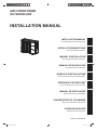
AIR CONDITIONER
OUTDOOR UNIT
INSTALLATION MANUAL
9332809039
9332808039_IM.indb 19332808039_IM.indb 1 2012-10-8 11:34:442012-10-8 11:34:44


 1
1
 2
2
 3
3
 4
4
 5
5


Fujitsu AOYG14LMCE Installation guide
Fujitsu AOHG09LMCA Installation guide
Fujitsu AOGG18LFCD Installation guide
Fujitsu ROG18LBCA Installation guide