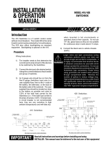
Code 3 950 & 960 Install Instructions

Category
Cars
Type
Install Instructions

Code 3 950 & 960 are versatile headlight flashers designed for emergency vehicles. They offer multiple flash patterns and can function as headlight flashers, non-DRL hot side switching flashers, or light bar flashers with steady burn override. With two independent outputs, each capable of handling up to 8 amps, these flashers provide ample power for various lighting configurations. Additionally, the units feature a kill switch that turns off both outputs when activated, allowing for easy deactivation of the flashers when needed.

Code 3 950 & 960 are versatile headlight flashers designed for emergency vehicles. They offer multiple flash patterns and can function as headlight flashers, non-DRL hot side switching flashers, or light bar flashers with steady burn override. With two independent outputs, each capable of handling up to 8 amps, these flashers provide ample power for various lighting configurations. Additionally, the units feature a kill switch that turns off both outputs when activated, allowing for easy deactivation of the flashers when needed.

1
INSTALLATION
& OPERATION
MANUAL
MODELS 950 & 960
MULTIPLE MODE
HEAD LIGHT FLASHERS
Contents:
Introduction.........................................................2
Unpacking & Pre-Installation..............................2
Installation & Mounting .......................................2
Mounting Methods ............................................ 2
Wire Functions..................................................3
Installation and Operation...................................4
Wiring Diagram...............................................4-5
Flash Mode Selection.........................................5
Testing the Headlight Flasher ............................5
Warranty .............................................................8
IMPORTANT:
MODELS 950 & 960 MULTIPLE
MODE HEAD LIGHT FLASHERS
Read all instructions and warnings before installing and using.
INSTALLER: This manual must be delivered to the end user of this equipment.
2
Introduction
The Code 3
®
Model 950 and 960 multiple mode flashers are solid state headlight flashers. Both models
can be used as a headlight flasher, non daytime running lights hot side switching flasher or as a light bar
flasher with steady burn override capability. The units allow the user one of three different headlight flasher
patterns. You may use either or all three patterns depending on installation.
Unpacking & Pre-installation
After unpacking your 950 or 960 Multiple Mode Flasher, carefully inspect the unit and associated parts for any
damage that may have been caused in transit. Report any damage to the carrier immediately.
Installation & Mounting
Mounting Methods
The units can be mounted using either the mounting tabs located at each end of the unit or the mounting
hole through the unit.
CAUTION: The unit must be mounted away from heat sources and water splashes.
All devices should be mounted in accordance with the manufacturer's instructions and
securely fasten to vehicle elements of sufficient strength to withstand the forces applied to
the device. Driver and/or passenger air bags (SRS) will affect the way equipment should
be mounted. This device should be mounted by permanent installation and within the
zones specified by the vehicle manufacturer, if any. Any device mounted in the deploy-
ment area of an air bag will damage or reduce the effectiveness of the air bag and may
damage or dislodge the device. Installer must be sure that this device, its mounting
hardware and electrical supply wiring does not interfere with the air bag or the SRS wiring
or sensors. Front or rear grille/bumper placement must avoid interference with SRS
sensors. Mounting the unit inside the vehicle by a method other than the permanent
installation is not recommended as unit may become dislodged during swerving, sudden
braking, or collision. Failure to follow instructions can result in personal injury.
WARNING!
!
The use of this or any warning device does not insure that all drivers can or will observe or
react to an emergency warning signal. Never take the right-of-way for granted. It is your
responsibility to be sure you can proceed safely before entering an intersection, driving
against traffic, responding at a high rate of speed, or walking on or around traffic lanes.
The effectiveness of this warning device is highly dependent upon correct mounting and
wiring. Read and follow the manufacturer’s instructions before installing or using this
device. The vehicle operator should insure daily that all features of the device operate
correctly. In use, the vehicle operator should insure the projection of the warning signal is
not blocked by vehicle components (i.e.: open trunks or compartment doors), people,
vehicles, or other obstructions.
This equipment is intended for use by authorized personnel only. It is the user’s responsi-
bility to understand and obey all laws regarding emergency warning devices. The user
should check all applicable city, state and federal laws and regulations.
Public Safety Equipment, Inc., assumes no liability for any loss resulting from the use of
this warning device.
Proper installation is vital to the performance of this warning device and the safe operation
of the emergency vehicle. It is important to recognize that the operator of the emergency
vehicle is under psychological and physiological stress caused by the emergency situation.
The warning device should be installed in such a manner as to: A) Not reduce the output
performance of the system, B) Place the controls within convenient reach of the operator
so that he can operate the system without losing eye contact with the roadway.
Emergency warning devices often require high electrical voltages and/or currents. Properly
protect and use caution around live electrical connections. Grounding or shorting of
electrical connections can cause high current arcing, which can cause personal injury and/
or severe vehicle damage, including fire. Incandescent lamps are extremely hot, allow to
cool completely before attempting to remove.
Any electronic device may create or be affected by electromagnetic interference. After
installation of any electronic device operate all equipment simultaneously to insure that
operation is free of interference. Never power emergency warning equipment from the
same circuit or share the same grounding circuit with radio communication equipment.
PROPER INSTALLATION COMBINED WITH OPERATOR TRAINING IN THE PROPER
USE OF EMERGENCY WARNING DEVICES IS ESSENTIAL TO INSURE THE SAFETY
OF EMERGENCY PERSONNEL AND THE PUBLIC.
WARNING!
!
3
Model Description
Model 950 - Positive output flasher. The Blue and Yellow output wires provide +12VDC output at up to 8
amps. each.
Model 960 - Negative (Ground) output flasher. The Blue and Yellow output wires provide a high current
ground path capable of sinking up to 8 amps. each.
Wire Functions
Red - Input: Battery Positive.
Supplies +12VDC for flasher operation. For Model 950 the Red wire also supplies the power to operate
the two highbeam headlight lamps. The flasher should be fused with a user supplied 20 amp. fuse and
wired with #14 AWG wire minimum.
Black - To Battery Negative (-).
Provides the flasher ground (earth). Use #14 AWG wire minimum. For best results, connect directly to
the negative (-) terminal of the battery. For Model 960 the Black wire is also the ground path for the
highbeam headlight circuit.
Orange - Flash Mode Control #1: Activated by +12VDC.
White - Flash Mode Control #2. Activated by +12VDC.
Blue - Output 1: 100 Watt (8 amps) Maximum.
Yellow - Output 2: 100 Watt (8 amps) Maximum.
Brown - Kill: Both Outputs OFF.
When activated by +12VDC through a user supplied switch or by connection to the vehicle's lowbeam
headlight circuit, both outputs will turn off simultaneously, as long as the Brown wire remains powered.
Connect to vehicle low beam circuit to automatically defeat the headlight flasher at night. This is an
OPTIONAL connection..
!
WARNING!
Larger wires and tight connections will provide longer service life for components. For high
current wires it is highly recommended that terminal blocks or soldered connections be used
with shrink tubing to protect the connections. Do not use insulation displacement
connectors (e.g. 3M
®
Scotchlock type connectors). Route wiring using grommets and
sealant when passing through compartment walls. Minimize the number of splices to
reduce voltage drop. High ambient temperatures (e.g. underhood) will significantly reduce
the current carrying capacity of wires, fuses, and circuit breakers. Use "SXL" type wire in
engine compartment. All wiring should conform to the minimum wire size and other
recommendations of the manufacturer and be protected from moving parts and hot
surfaces. Looms, grommets, cable ties, and similar installation hardware should be used to
anchor and protect all wiring.
Fuses or circuit breakers should be located as close to the power takeoff points as possible
and properly sized to protect the wiring and devices.
Particular attention should be paid to the location and method of making electrical
connections and splices to protect these points from corrosion and loss of conductivity.
Ground terminations should only be made to substantial chassis components, preferably
directly to the vehicle battery.
The user should install a fuse sized to approximately 125% of the maximum Amp capacity
in the supply line to protect against short circuits. For example, a 30 Amp fuse should
carry a maximum of 24 Amps. DO NOT USE 1/4" DIAMETER GLASS FUSES AS THEY
ARE NOT SUITABLE FOR CONTINUOUS DUTY IN SIZES ABOVE 15 AMPS. Circuit
breakers are very sensitive to high temperatures and will "false trip" when mounted in hot
environments or operated close to their capacity.
4
FIGURE 1: WIRING DIAGRAM FOR 950
HEADLIGHT FLASHER INSTALLATION
Installation and Operation
Installation
Follow the steps below to properly install your 900 Series Headlight Flasher. Refer to Figure 1 while
installing the Model 950 Headlight Flasher. Refer to Figure 2 while installing the 960 Headlight Flasher.
Refer to the vehicle manufacturer's maintenance manual for detailed information on the headlight wiring.
NOTE: Use #14 AWG wire minimum for the headlight and power/ground connections and 18 AWG wire
minimum for the Orange, White and Brown control wire connections.
1) Mount the Flasher Unit in a convenient location away from direct heat sources or water
splashes. A common location is in the grill area near the passenger's side headlight assembly.
Use either mounting method mentioned under “Mounting Methods,” above.
2) Connect a user supplied fuse holder in-line between the positive (+) post of the battery and Red
wire of the Flasher Unit.
CAUTION: Leave the fuse out of the fuse holder until ready to test the completed installation.
3) Install a user supplied switch in a convenient location on the instrument panel near the driver.
4) Near the Passenger's side headlight assembly, locate and cut the wire going to the Driver's
side highbeam headlight circuit.
5) Connect the Passenger's side highbeam headlight wire to the Blue wire of the Flasher Unit.
The Passenger's side highbeam headlight wire should still be connected to the vehicle's
highbeam control wire.
6) Connect the Driver's side headlight high beam wire to the Yellow wire of the Flasher Unit.
7) (OPTIONAL) Connect the vehicle’s low beam headlight circuit to the Brown wire of the Flasher
Unit.
NOTE: For continued high beam flash when the low beam lights are on, do not connect the Brown wire.
8) Connect the negative (-) post of the battery, or other good ground(earth), to the Black wire of
the Flasher Unit.
Double check all of your connections then refer to the section on testing the circuit.
Model
950
5
Flash Mode Selection
The Model 950 or 960 flash mode is selected during installation by choosing how the orange and the white
control wires are connected as indicated in the list below.
Connect the user supplied switch between positive +12VDC and the orange and/or white
control wires of the flasher unit to get the desired flash.
Slow Wig/Wag (alternating) flash: Orange to switched +12VDC; White not used.
Fast Wig/Wag (alternating) flash: White to switched +12VDC; Orange not used.
Cycle Flash; Orange & White to switched +12VDC
Double check all of your connections then refer to the section on testing the flasher.
Testing the Headlight Flasher.
1) Install a 20A fuse in the in-line fuse holder for Model 950 Flashers.
Install a 3A fuse in the in-line fuse holder for Model 960 Flashers.
2) Turn ON the control switch. The high beam headlights should flash. The
pattern is dependent on flasher mode selected (see Flash Pattern Selection above).
3) Turn ON the vehicle’s low beam headlights. The low beams should burn steady.
NOTE: If you connected the brown wire to the vehicle's low beam circuit, the headlight flasher will go off
when you turn on the low beams. If you want the high beams to continue to flash, DO NOT connect the
brown wire.
4) Turn ON the vehicle’s high beams. The high beams should now be on and the headlight
flasher should be disabled.
If the flasher does not work according to the above description, recheck all of your connections.
FIGURE 2: WIRING DIAGRAM FOR 960
HEADLIGHT FLASHER INSTALLATION
Model
960
6
NOTES
7
NOTES
Public Safety Equipment, Inc.
10986 N. Warson Road
St. Louis, Missouri 63114-2029USA
Ph. (314) 426-2700 Fax (314) 426-1337
www.code3pse.com
Revision 0, 5/2006 - Instruction Book Part No. T11435
©2006 Public Safety Equipment, Inc. Printed in USA
WARRANTY
Code 3
, Inc.'s emergency devices are tested and found to be operational at the time of
manufacture. Provided they are installed and operated in accordance with manufacturer's
recommendations, Code 3
, Inc. guarantees all parts and components except the lamps to a period
of 1 year (unless otherwise expressed) from the date of purchase or delivery, whichever is later.
Units demonstrated to be defective within the warranty period will be repaired or replaced at the
factory service center at no cost.
Use of lamp or other electrical load of a wattage higher than installed or recommended by the
factory, or use of inappropriate or inadequate wiring or circuit protection causes this warranty to
become void. Failure or destruction of the product resulting from abuse or unusual use and/or
accidents is not covered by this warranty. Code 3
, Inc. shall in no way be liable for other damages
including consequential, indirect or special damages whether loss is due to negligence or breach of
warranty.
CODE 3
Ò
, INC. MAKES NO OTHER EXPRESS OR IMPLIED WARRANTY INCLUDING,
WITHOUT LIMITATION, WARRANTIES OF FITNESS OR MERCHANTABILITY, WITH RE-
SPECT TO THIS PRODUCT.
PRODUCT RETURNS
If a product must be returned for repair or replacement*, please contact our factory to obtain
a Return Goods Authorization Number (RGA number) before you ship the product to Code 3
,
Inc. Write the RGA number clearly on the package near the mailing label. Be sure you use
sufficient packing materials to avoid damage to the product being returned while in transit.
*Code 3
, Inc. reserves the right to repair or replace at its discretion. Code 3
, Inc. assumes no responsibility or liability for expenses incurred for the
removal and /or reinstallation of products requiring service and/or repair.; nor for the packaging, handling, and shipping: nor for the handling of products return to
sender after the service has been rendered.
For Technical Support / Service, please call 314-996-2800.
Code 3, Inc.
is a registered trademark of Public Safety
Equipment, Inc.
  • Page 1 1
  • Page 2 2
  • Page 3 3
  • Page 4 4
  • Page 5 5
  • Page 6 6
  • Page 7 7
  • Page 8 8

Code 3 950 & 960 Install Instructions

Category
Cars
Type
Install Instructions

Code 3 950 & 960 are versatile headlight flashers designed for emergency vehicles. They offer multiple flash patterns and can function as headlight flashers, non-DRL hot side switching flashers, or light bar flashers with steady burn override. With two independent outputs, each capable of handling up to 8 amps, these flashers provide ample power for various lighting configurations. Additionally, the units feature a kill switch that turns off both outputs when activated, allowing for easy deactivation of the flashers when needed.

Ask a question and I''ll find the answer in the document

Finding information in a document is now easier with AI