Page is loading ...

Satellite Television
KVHTracVision
®
G4
technical
manual
•
Installation
•
Configuration
•
Maintenance
A Guide to TracVision G4

TVG4_TM_cover_540147_Rev.K
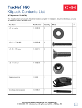
12 1110987612543 13 14 232221201918 24171615 25 26 353433323130 36292827
48 47 383940414243 3744454660 59 505152535455 49565758
Green/White
White/Green
Blue/White
White/Blue
Brown/White
White/Brown
Gray/White
White/Orange
Orange/White
White/Gray
Data Cable
Black
Red
TracVision
Power
Ground
+12 VDC
Ship’s
Power
(11-16 VDC)
Not
Used
Not Used
Green/White
White/Green
White/Blue
Blue/White
White/Orange
Orange/White
GyroTrac Sensor
Module Cable
Wiring Color Code Definitions
First Color: Wire
Second Color: Tracer
Example: Red/Orange = Red Wire with Orange Tracer
TracVision G4 will suffer serious
damage if connected to power in
excess of 16 VDC. Complete details
regarding connecting TracVision G4
to ship's power have been provided in
"Connecting
the ADCU to Vessel Power" on page 37.
Gyro Power
Ground
Gyro RXD+
Gyro RXD-
Gyro TXD-
Gyro TXD+
Not Used
IRD Ground Wire
(to IRD)
TracVision G4 can either receive power
through the ADCU (as illustrated in
the diagram) or directly from ship’s
power if that is more convenient.
Refer to
"Alternate Method of Providing Power to
the Antenna" on page 32
for details.
TracVision
®
G4 Wiring Quick Reference Guide

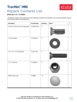
GyroTrac Mode Menus
Setup display type?
Enter Next Return
Setup data outputs?
Yes Next Return
Setup configuration?
Yes Next Return
Get Antenna status?
Enter Next Return
control antenna?
Enter Next Return
Select Mag/True
Select Serial Port 1, 2, or 3
Set NMEA Outputs
Select Mag/True
Control Compass?
Enter Next Return
Autocalibration On or Off
Calibration Accuracy, Magnetic
Environment, and Calibration #
Compass Calibration Reset
Set AutoCal On/Off?
Yes Next Return
Read Cal score?
Yes Next Return
Clear Compass Cal?
Yes Next Return
The Control Compass Menus are only
available if the selected heading
reference source is INTERNAL.
Magnetic Heading
###.#°
Mag/HDG True/HDG
###.#° ###.#°
Pitch Roll Yaw
#.#° #.#° #.#°
Mag/Hdg Rate/Sec
#.#° #.#°
Tracking <Sat Name>
###.#° ##.#° ####
ANTENNA Initializing
No Antenna Information
Lat: ##
Long: ##
compass?
Yes Next Return
Pitch, Roll & Yaw?
Yes Next Return
Rate of Turn?
Yes Next Return
Latitude Longitude?
Yes Next Return
Antenna display?
Yes Next Return
Set Reference Voltage
Set Swing Voltage
Set Speed
Select Output Type
Set Data Rate
Set sine-cos levels?
Yes Next Return
Set serial outputs?
Yes Next Return
Set Furuno outputs?
Yes Next Return
Select Internal or External
Heading Reference Source
TV Antenna Communication
On or Off
Set Heading int/ext?
Yes Next Return
Set Gyro Offsets?
Yes Next Return
Default Display box?
Yes Next Return
Set TV com on/off?
Yes Next Return
Display Default
Set Offset Roll
Set Offset Yaw
Set Offset Pitch
Errors Detected
Antenna Type and Version
Antenna Serial Number
Threshold and
Signal Levels
LNB Skew Angle
Get System Errors?
Yes Next Return
Get Thres/sig level?
Yes Next Return
Get version?
Yes Next Return
Get serial number?
Yes Next Return
Get skew angle?
Yes Next Return
Bit Error Rate
Get bit error rate?
Yes Next Return
* ARE YOU SURE? *
Yes No
** WARNING **
Data will be HALTED
Alert Screens
Certain operations temporarily halt data
output. In this event, the ADCU will display a
set of alert screens. Select “Yes” to proceed,
“No” to return to the Main Data Display.
Dim or Brighten
ADCU Display
Set brightness?
Yes Next Return
Return to Selected Primary Display
GyroTrac
™
Advanced Digital Control Unit (ADCU) Menu Quick Reference Guide
ADCU Primary Display Options
Pitch Roll Yaw
#.#° #.#° #.#°
Pitch, Roll, Yaw
Mag/Hdg Rate/Sec
#.#° #.#°
Rate of TurnCompass Displays*
* True North Display requires GPS data
Magnetic Heading
###.#°
Mag/HDG True/HDG
###.#° ###.#°
Antenna Displays
Tracking <Sat Name>
###.#° ##.#° ####
ANTENNA Initializing
No Antenna Information
SELECTED DISPLAY
Select Installed
Satellite A
Select Installed
Satellite B
Enter GyroTrac Mode Menus
Lat: ##
Long: ##
Latitude/Longitude
†
†
Lat/Long Display requires GPS data
See
"Alert Screens" on page 65
for more details.
See Section 3.3 for details See Section 3.4 for details See Section 3.5 for details See Section 3.6 for details See Section 3.7 for details See Section 3.8 for details
See Section 3.2 for details
Antenna Restarts
Set Latitude
Set Longitude
Select Active Satellite
Man control antenna?
Yes Next Return
Restart antenna?
Yes Next Return
Install satellite?
Yes Next Return
Set Lat/Long?
Yes Next Return
Adjust Azimuth
Adjust Elevation
Install Sat Pair
Set Latitude
Set Longitude
Restart Antenna
Sleep Mode On/Off
Set sleep on/off?
Yes Next Return
Instant On Mode On/Off
set instant on/off?
Yes Next Return
Update Frequency
Sat frequency scan?
Yes Next Return
Select Satellite?
Yes Next Return

TracVision G4-HP
Technical Manual Addendum
(ECO #7622)
The following changes apply to Revision K of the
TracVision G4-HP Technical Manual (KVH Part Number 54-0147).
5.3 TracVision G4 Field
Replaceable Units
Table 5-1 has been updated to show the new part number for the RF PCB.
FRU Part Number
Radome 02-0925-03
Main PCB 02-0992
RF PCB 02-1524
Antenna Gyro Sensor 02-1090
Antenna Gyro Gasket 24-0139
Elevation Drive Belt 24-0105-104
Elevation Motor 02-1356
North American LNB
†
02-0870
European LNB
††
02-1278
Data Cable 32-0619-50
†
32-0619-100
††
RF Cable 32-0417-50
†
PC Cable 32-0628-06
Power Cable 32-0510-50
Ground Cable 32-0583-50
CPU Fuses 16-0017-3150
†
North American system
††
European system
1
54-0147 Addendum to Rev. K
Table 5-1
TracVision G4 Field
Replaceable Units

TracVision G4-HP
Technical Manual Addendum
Sky Mexico Customers Only
(ECO #7247)
The following changes apply to Revision K of the
TracVision G4-HP Technical Manual (KVH Part Number 54-0147).
Installed Satellites
The Sky Mexico satellite TV service is broadcast via the PAS 9
satellite located at 58º West longitude. Therefore, the Sky Mexico-
configured antenna (KVH part number 01-0231-05HPT) is
programmed to track the following satellites:
If you choose, you can install any other satellite from the
antenna’s satellite library as Satellite B (following the procedure
in Section 2.9, “Installing Satellites Using the ADCU” on page 44).
However, please note that the antenna may not be able to find
your selected second satellite when you switch from PAS_9 to
Satellite B, since the satellite may not be viewable from your
location. For example, in Mexico, you can receive Sky Mexico signals
from PAS 9, but you cannot receive signals from DSS_101, which
provides DIRECTV service to the U.S.
Multiswitch Restrictions
If you need to connect more than two receivers to the antenna
system for PAS 9 service, you must use an active multiswitch
that generates a 22 KHz tone (for example, Spaun models
5602NF or 5802NF).
1
54-0147 Addendum to Rev. K
Satellite A Satellite B
PAS_9 NONE

LNB “Skew” Adjustment
Unlike most satellite TV signals in North America, which are
circularly polarized, the PAS 9 signal is linearly polarized, which
means it is transmitted in a certain orientation. Your Sky Mexico-
configured antenna is equipped with a special LNB that collects
these linear signals. To optimize reception, however, the LNB
must be oriented in the same way as the satellite signal. This
orientation adjustment is referred to as the LNB’s “skew.”
Figure 1 shows how skew determines the amount of signal the
LNB collects. The more signal it collects, the better the reception.
To set the skew, you simply need to rotate the LNB to the proper
angle, as shown in Figure 2.
The correct skew setting varies depending on your geographic
location, since the orientation of your antenna to the satellite
changes as you move. Follow the instructions on the following
pages to find the correct skew for your location and to adjust the
LNB’s skew setting.
2
54-0147 Addendum to Rev. K
Ideal SkewGood SkewBad Skew
= Satellite Signal = LNB "Signal Collector"
Figure 1
How Skew Works
Figure 2
LNB Can Be Rotated to Adjust Skew

Finding the Correct Skew for Your Location
You can find the correct skew for your location by either:
A. Querying the antenna (by entering commands via
a laptop connection), or
B. Finding your location on the PAS 9 skew map.
Option A
- Querying the Antenna
To find the correct skew, follow the steps below.
1. Turn on the antenna and allow the antenna to
initialize.
2. Press the center button on the ADCU until the
“Control Antenna?” screen appears.
3. Press the ENTER button to access the Control
Antenna Mode.
4. Press the NEXT button until the “Set Lat/Long?”
screen appears.
5. Follow the process shown in “Setting Latitude and
Longitude” on page 86 to enter your position into
the antenna.
6. After you’ve entered your position, press the
NEXT button until the “Restart Antenna?” screen
appears.
7. Press the YES button to restart the antenna.
8. Once the antenna has initialized, press the center
button on the ADCU until the “Get Antenna
Status?” screen appears.
9. Press the ENTER button to access the Antenna
Status Mode.
10. Press the NEXT button until the “Get Skew
Angle?” screen appears.
11. Press the YES button. The ADCU displays the
correct skew for the location you entered in Step 5.
3
54-0147 Addendum to Rev. K
Skew angle
65.5
Figure 3
ADCU Reports Skew Angle (Example)

Option B - Using the PAS 9 Skew Map
If you do not have a laptop, you can find the approximate skew
for your location using the map below.
When to Change the Skew
In general, if your LNB’s skew is set to within ± 8º of the ideal
skew for your location, the antenna should continue to provide
good satellite TV reception. However, if you travel to a location
in which your LNB’s skew differs by 9º or more, or if reception
degrades the further you travel, you should readjust the LNB’s
skew for your new location.
Example: If you traveled from El Salvador to Acapulco along the
coast, you wouldn’t need to change the skew, since the correct
skew is 66º for both locations. Even if you continued traveling
north to Cabo San Lucas, you should still have good satellite TV
reception, since the correct skew is 63º, a 3º difference. However,
if you traveled all the way to San Diego, where the correct skew
is 54º, a 12º difference, you might then need to readjust the skew
to enjoy satellite TV reception.
4
54-0147 Addendum to Rev. K
+70
+65
+60
+55
+50 +45 +40 +35 +30
Figure 4
Approximate Skew Settings for PAS 9 Satellite

Setting the Skew
To set your LNB to the proper skew, follow the steps below.
1. Turn off the power to the antenna.
2. Remove the radome and set it aside in a safe place.
3. Loosen the two wing screws securing the LNB
within the choke feed, as shown in Figure 5.
4. Refer to the skew labels on the end of the LNB and
on the LNB choke feed (shown in Figure 6) and
adjust the LNB as necessary to match as closely as
possible the correct skew.
5. Retighten the wing screws.
6. Reinstall the radome.
5
54-0147 Addendum to Rev. K
Figure 5
LNB Skew Adjustment
Figure 6
Skew Labels
Skews for PAS 9 are all positive (+)
angles. Do not set the skew to a
negative number.
Positive
Skews

TracVision G4-HP
Technical Manual Addendum
(ECO #7243)
The following changes apply to Revision K of the
TracVision G4-HP Technical Manual (KVH Part Number 54-0147).
“Instant On” Mode Default Setting Is OFF
The default setting for Instant On Mode is now OFF, not ON.
When Instant On is set to ON, the antenna skips the startup
process to immediately receive the TV signal, as long as the
vessel has not moved since the antenna was last shut off. See
Section 3.8, “Control Antenna Mode” for details.
Antenna Restarts After =CALGYRO Command
When the antenna receives an =CALGYRO command, it
calibrates the gyro then restarts. This eliminates the need to enter
a
ZAP command following the calibration process.
If you need to calibrate the gyro, follow the updated procedure
below. This procedure replaces the “Calibrating the Antenna
Gyro” instructions in Section 5.6, “Replacing the Antenna Gyro
Assembly.”
1. With a PC connected to the ADCU’s maintenance
port, apply power to the antenna unit.
2. Type
HALT<cr
>>
(<cr> = Press the ENTER key)
while the system is performing the limit switch
initialization routine.
3. Type
DEBUGON<cr> to enter Debug mode.
4. Type
=LSTEST<cr>.
5. Type
EL,300<cr>.
6. Type
=CALGYRO<cr>. Verify that the Antenna
Gyro Azimuth scale factor is between -0.00090 and
-0.00110 and the Antenna Gyro Elevation scale
factor is between 0.00090 and 0.00110.
The antenna restarts. The gyro calibration process is
complete!
1
54-0147 Addendum to Rev. K
If your vessel is moored in calm
waters, you might be able to turn
on your receiver while leaving the
antenna turned off. As long as the
vessel has not moved since you
last turned off the antenna, you
might still get good TV reception.
However, once the vessel moves
and reception is lost, you will then
need to turn the antenna back on to
reacquire the satellite and resume
active tracking.
Refer to
Section 4.6, “Computer
Diagnostics”
for details on
connecting a PC to the
maintenance port.

1
54-0147 Addendum to Rev. K
TracVision G4-HP
Technical Manual Addendum
(ECO #7134)
The following changes apply to Revision K of the
TracVision G4-HP Technical Manual (KVH Part Number 54-0147).
The “=TV” configuration command printed in the manual is incorrect.
For your TracVision G4-HP system, the correct configuration command
is
=TVG4HPT
, not
=TVG4HP
.
You will need to enter the
=TVG4HPT
command whenever you replace
the main printed circuit board (PCB) or calibrate the antenna gyro, at
the steps noted below.
5.4 Replacing the Main PCB and
Fuses
Replacing the Main PCB
13. Type =TVG4HPT<cr> (<cr> = Press the Enter key).
5.6 Replacing the Antenna Gyro
Assembly
Calibrating the Antenna Gyro
8. Type =TVG4HPT<cr>.

TracVision G4
Technical Manual
This manual provides detailed instructions on the proper
installation, configuration, troubleshooting, and maintenance of
the KVH TracVision G4 system. Complete instructions on how to
use the TracVision G4 system is provided in the TracVision G4
User’s Guide.
Throughout this manual, important information is marked for
your attention by these icons:
Direct questions, comments, or suggestions to:
KVH Industries, Inc. KVH Europe A/S
50 Enterprise Center Kokkedal Industripark 2B
Middletown, RI 02842-5279 USA 2980 Kokkedal, Denmark
Tel: +1 401 847-3327 Tel: +45 45 160 180
Fax: +1 401 849-0045 Fax: +45 45 160 181
E-mail: [email protected] E-mail: [email protected]
Internet: www.kvh.com Internet: www.kvh.com
If you have any comments regarding this manual, please e-mail
them to [email protected]. Your input is greatly appreciated!
A helpful tip that either directs you to
a related area within the manual or
offers suggestions on getting the
best performance from your system.
An alert to important information
regarding procedures, product
specifications, or product use.
An electrical safety warning to help
identify electrical issues that can be a
hazard to either this KVH product or
a user.
Information about installation,
maintenance, troubleshooting, or
other mechanical issues.
KVH Part # 54-0147 Rev. K
© 2004, KVH Industries, Inc. All rights reserved.
TracVision G4 Serial Number
This serial number will be required
for all troubleshooting or service
calls made regarding this product.
Welcome to TracVision G4
Click here to go to our state-
of-the-art Customer Support
web page...the fastest and
easiest way to get all of your
questions answered!

TracVision
®
and KVH
®
are registered trademarks
of KVH Industries, Inc.
GyroTrac
™
and TracNet
™
are trademarks of KVH Industries, Inc.
DVB
®
(Digital Video Broadcasting) is a registered trademark of the DVB Project.
DIRECTV
®
is a registered trademark of DIRECTV, Inc.,
a unit of the DIRECTV Group.
DISH Network
™
is an official trademark of
EchoStar Communications Corporation.
ExpressVu is a property of Bell ExpressVu, a wholly owned
subsidiary of Bell Satellite Services.
Cetrek
™
is a trademark of Cetrek USA.
Furuno
®
is a registered trademark of Furuno USA, Inc.
B&G
®
and Halcyon
®
are trademarks of Brooks and Gatehouse, Inc.

54-0147
i
Table of Contents
Table of Contents
1 Introduction . . . . . . . . . . . . . . . . . . . . . . . . . . . . . . . . . .1
1.1 TracVision G4 System Overview . . . . . . . . . . . . . . . . . . . . .3
1.2 TracVision G4 Components . . . . . . . . . . . . . . . . . . . . . . . . .5
1.3 Materials Provided With the TracVision G4 . . . . . . . . . . . . .6
2 Installation . . . . . . . . . . . . . . . . . . . . . . . . . . . . . . . . . . .7
2.1 Planning the Installation . . . . . . . . . . . . . . . . . . . . . . . . . . . .9
2.2 Mounting the TracVision Antenna . . . . . . . . . . . . . . . . . . . .15
2.3 Mounting the GyroTrac Sensor . . . . . . . . . . . . . . . . . . . . .19
2.4 Mounting the ADCU . . . . . . . . . . . . . . . . . . . . . . . . . . . . . .24
2.5 Connecting the IRD(s) . . . . . . . . . . . . . . . . . . . . . . . . . . . .26
2.6 Wiring the ADCU . . . . . . . . . . . . . . . . . . . . . . . . . . . . . . . .29
2.7 Calibrating the Sensor . . . . . . . . . . . . . . . . . . . . . . . . . . . .40
2.8 Activating/Programming the IRD . . . . . . . . . . . . . . . . . . . .42
2.9 Installing Satellites Using the ADCU . . . . . . . . . . . . . . . . .44
2.10 Setting the Skew Angle
(European Systems Only) . . . . . . . . . . . . . . . . . . . . . . . . .54
2.11 Checking Out the System . . . . . . . . . . . . . . . . . . . . . . . . .55
2.12 Changing Geographic Location . . . . . . . . . . . . . . . . . . . . .57
3 Using the ADCU Interface . . . . . . . . . . . . . . . . . . . . . . . .59
3.1 Startup and Self-test . . . . . . . . . . . . . . . . . . . . . . . . . . . . .61
3.2 Data Display and Accessing the Main Menu . . . . . . . . . . .63
3.3 Setup Display Mode . . . . . . . . . . . . . . . . . . . . . . . . . . . . . .67
3.4 Set Data Outputs Mode . . . . . . . . . . . . . . . . . . . . . . . . . . .68
3.5 Set Configuration Mode . . . . . . . . . . . . . . . . . . . . . . . . . . .73
3.6 Control Compass Mode . . . . . . . . . . . . . . . . . . . . . . . . . . .77
3.7 Antenna Status Mode . . . . . . . . . . . . . . . . . . . . . . . . . . . . .79
3.8 Control Antenna Mode . . . . . . . . . . . . . . . . . . . . . . . . . . . .81

4 Troubleshooting . . . . . . . . . . . . . . . . . . . . . . . . . . . . . . .91
4.1 Troubleshooting Matrix . . . . . . . . . . . . . . . . . . . . . . . . . . . .93
4.2 Causes and Remedies for Common
Operational Issues . . . . . . . . . . . . . . . . . . . . . . . . . . . . . . .94
4.3 GyroTrac-specific Issues . . . . . . . . . . . . . . . . . . . . . . . . . .97
4.4 IRD Troubleshooting . . . . . . . . . . . . . . . . . . . . . . . . . . . . . .98
4.5 Antenna Gyro and LNB Faults . . . . . . . . . . . . . . . . . . . . . .98
4.6 Computer Diagnostics . . . . . . . . . . . . . . . . . . . . . . . . . . . .98
4.7 Maintenance Port Parser Commands . . . . . . . . . . . . . . . .99
5 Maintenance . . . . . . . . . . . . . . . . . . . . . . . . . . . . . . . .101
5.1 Warranty/Service Information . . . . . . . . . . . . . . . . . . . . . .103
5.2 Preventive Maintenance . . . . . . . . . . . . . . . . . . . . . . . . . .103
5.3 TracVision G4 Field Replaceable Units . . . . . . . . . . . . . .104
5.4 Replacing the Main PCB or Fuses . . . . . . . . . . . . . . . . . .106
5.5 Replacing the RF PCB . . . . . . . . . . . . . . . . . . . . . . . . . . .109
5.6 Replacing the Antenna Gyro Assembly . . . . . . . . . . . . . .111
5.7 Replacing the Elevation Motor and Belt . . . . . . . . . . . . . .114
5.8 Replacing the LNB . . . . . . . . . . . . . . . . . . . . . . . . . . . . . .116
5.9 GyroTrac Field Replaceable Units . . . . . . . . . . . . . . . . . .118
5.10 Preparation for Shipment . . . . . . . . . . . . . . . . . . . . . . . . .119
Appendices . . . . . . . . . . . . . . . . . . . . . . . . . . . . . . . . . . . . .121
A System Specifications . . . . . . . . . . . . . . . . . . . . . . . . . . .123
B TracVision G4 Baseplate Mounting Holes Template . . . .127
C ADCU Flush Mount Panel Template . . . . . . . . . . . . . . . . .129
D Comprehensive TracVision G4 System
Wiring Diagram . . . . . . . . . . . . . . . . . . . . . . . . . . . . . . . . .131
E Optional Rotating Card Display . . . . . . . . . . . . . . . . . . . .135
F Startup Data Sequences . . . . . . . . . . . . . . . . . . . . . . . . .143
G GyroTrac Data Outputs . . . . . . . . . . . . . . . . . . . . . . . . . .145
H Maintenance Port Parser Commands . . . . . . . . . . . . . . .151
54-0147
ii
TracVision G4 Technical Manual

Introduction
54-0147
1
1 – Introduction
This section provides a basic overview of the TracVision G4 system. It
explains how the system works and describes the function of each
component.
Contents
1.1 TracVision G4 System Overview . . . . . . . . . . . . . . . . . . . . . . . . . . .3
1.2 TracVision G4 Components . . . . . . . . . . . . . . . . . . . . . . . . . . . . . . .5
1.3 Materials Provided With the TracVision G4 . . . . . . . . . . . . . . . . . . .6

Introduction
54-0147
3
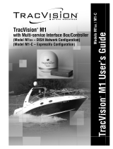
1.1 TracVision G4 System Overview
A complete satellite TV system, illustrated in Figure 1-1, includes
the TracVision G4 antenna unit connected to the GyroTrac digital
gyro-stabilized sensor, Advanced Digital Control Unit (ADCU),
an IRD (satellite TV receiver), and a television set. A desktop or
laptop computer is used to conduct diagnostics. System
specifications are provided in Appendix A on page 123.
System Compatibility
The TracVision G4 satellite antenna is fully compatible with
Digital Video Broadcasting (DVB
®
) satellites, as well as
DIRECTV
®
‘s Digital Satellite Service (DSS) satellites. The
system is also fully compatible with KVH’s TracNet
™
2.0 Mobile
High-speed Internet System (for more information about
TracNet 2.0, please visit our web site at www.kvh.com).
In-motion Tracking
The TracVision G4 uses a state-of-the-art actively stabilized
antenna system. Once the satellite is acquired, the antenna gyro
continuously measures the heading, pitch, and roll of your vessel
and sends commands to the antenna motors to keep the antenna
pointed at the satellite at all times.
Satellite Receiver 2
Satellite Receiver 1
Options Purchased Separately
GyroTrac Sensor
Advanced Digital
Control Unit (ADCU)
TracVision G4 Antenna
Interfaces to:
Autopilots
Radars
Plotters
Remote Displays
PC Diagnostics
GPS or
Ship's Gyro
11-16 VDC
3.5 - 4.5 Amps
Power
RF
TV 1
TV 2
RF
Data
Figure 1-1
TracVision G4 System Diagram
TracVision
Figure 1-2
TracVision Identifies and
Compensates for Vessel Motion

54-0147
4
TracVision G4 Technical Manual
Satellite Library
Your TracVision G4 includes a pre-programmed satellite library
of North American and European satellite services. When
configuring the TracVision G4, you may choose a pair of satellites
from the library to be active in the system and with your IRD.
For the antenna to track and receive signals from two satellites,
they must be within 10º longitude of each other in orbit. As a
result, certain satellites can be paired only with certain other
satellites. Tables 1-1 and 1-2 list the possible satellite pairs that
may be selected in North America and Europe. If the satellite
service you wish to receive is not listed in the satellite library, you may
add two additional satellites of your choice to the library.
TracVision G4’s default satellite
pairs are:
N. America (US DIRECTV):
DSS_101 & DSS_119
Europe: Astra 1 & Hotbird
Table 1-2
Available Satellite Pairs - Europe
(European LNB required)
DSS_101 ✓✓✓
DSS_119 ✓✓✓
Echo_61 ✓✓ ✓✓
Echo_110 ✓ ✓✓✓✓
Echo_119 ✓✓ ✓✓✓
Echo_148 ✓✓ ✓✓
Expressvu ✓✓✓✓✓✓ ✓
ExpressTV ✓✓✓✓✓✓✓
DSS_101 DSS_119 Echo_61 Echo_110 Echo_119 Echo_148 Expressvu ExpressTV
Table 1-1
Available Satellite Pairs
- North America
(North American LNB required)
Astra 1 ✓✓ ✓✓
Astra 2N ✓✓
Astra 2S ✓✓
Hispasat
Hotbird ✓✓ ✓ ✓
Sirius ✓✓✓
Thor ✓
Astra 1 Astra 2N Astra 2S Hispasat Hotbird Sirius Thor

1.2 TracVision G4 Components
Your TracVision G4 system includes the following components:
Antenna Unit
The antenna unit houses the antenna positioning mechanism, low
noise block (LNB), power supply, and control elements within a
molded ABS radome. Weathertight connectors on the bottom of
the baseplate join the power, signal, and control cabling from
belowdecks units.
GyroTrac
TracVision G4 includes KVH’s GyroTrac digital gyrocompass for
three-axis attitude/heading reference, ensuring superior open
water performance in any sea conditions. GyroTrac can also
operate as a fully functional, stand-alone heading sensor.
GyroTrac includes the following two components:
Sensor Module
The sensor module houses the system’s compass/yaw sensor,
inclinometer, rate gyros, and processing electronics and is
waterproof to a depth of one meter.
Advanced Digital Control Unit (ADCU)
The ADCU is the user interface, providing access to the system
and its functions through an LCD and three soft keys. The ADCU
also serves as the system’s junction box, allowing the system to
use ship’s power, interface with the sensor module, supply and
receive data to/from the TracVision G4 system, and supply and
receive data to/from other shipboard systems.
Integrated Receiver Decoder (IRD)
(Satellite TV Receiver)
The IRD (purchased separately) receives satellite signals from the
antenna unit for signal processing and channel selection, and
sends the signals to the TV set for viewing. Please refer to the
user’s manual provided with your selected IRD for complete
operating instructions.
Introduction
54-0147
5
Before you can start watching
satellite TV using your TracVision
antenna, you will need to activate
your IRD. Refer to
Section 2.8,
“Activating/Programming the IRD”
on page 42
for details.

1.3 Materials Provided With the
TracVision G4
Table 1-3 lists the components and materials in the TracVision G4
shipping carton.
Component KVH Part No.
Antenna Unit 02-0989-01HP
†
02-0989-02HP
††
Installation Kitpack 72-0099
Data Cable 32-0619-50
†
32-0619-100
††
PC Cable 32-0628-06
RF Cable* 32-0417-50
Power Cable 32-0510-50
Ground Cable 32-0583-50
TracVision G4 Technical Manual
54-0147
TracVision G4 User’s Guide
54-0147-01
GyroTrac, which includes: 01-0226-01
Sensor Module 02-1154
ADCU 02-0961
Flush Mount ADCU Panel 20-0667
Horizontal Sensor Bracket 20-0658
Vertical Sensor Bracket 20-0666
Sensor to ADCU Cable 32-0623-30
Kitpack 72-0095
†
North American system
††
European system
* Not included with European systems
54-0147
6
TracVision G4 Technical Manual
Table 1-3
TracVision G4 Packing List
For lists of items supplied in the
kitpacks, see Tables 2-3 and 2-4 on
page 10.
/