
P.O. Box 309, Menomonee Falls, WI USA 53052-0309
PHONE 800.BRADLEY (800.272.3539) FAX 262.251.5817
bradleycorp.com
Installation
215-1082 Rev. F; ECN 08-521
© 2008 Bradley Corporation
Page 1 of 16 9/26/08
S19-300T
top supply
alimentation par le haut
abastecimiento superior
S19-300B
bottom supply
alimentation par le bas
abastecimiento inferior
Heat Trace Combination Drench Shower and Eyewash
Unit (includes 120 V and 220/240 V versions)
Combiné douche lave/yeux avec élément chauffant
(inclut les versons 120 V et 220/240 V)
Combinación de ducha de aspersión/lavaojos con
control térmico (incluye las versiones de 120 V y
220/240 V)
Table of Contents
Pre-Installation Information . . . . . . . . . . . . . . . . . . 2
Assembly of Components . . . . . . . . . . . . . . . . . . . 2
Installation . . . . . . . . . . . . . . . . . . . . . . . . . . . . . 3–4
Repair Parts List . . . . . . . . . . . . . . . . . . . . . . . . . . 4
Repair Parts. . . . . . . . . . . . . . . . . . . . . . . . . . . . . . 5
Troubleshooting . . . . . . . . . . . . . . . . . . . . . . . . . . . 6
Table des matières
Avant l’installation . . . . . . . . . . . . . . . . . . . . . . . . . 7
Assemblage des composantes . . . . . . . . . . . . . . . 7
Installation . . . . . . . . . . . . . . . . . . . . . . . . . . . . . 8–9
Liste des pièces de rechange . . . . . . . . . . . . . . . . 9
Pièces de rechange. . . . . . . . . . . . . . . . . . . . . . . 10
Dépannage . . . . . . . . . . . . . . . . . . . . . . . . . . . . . 11
Contenido
Información previa a la instalación . . . . . . . . . . . 12
Armado de los componentes. . . . . . . . . . . . . . . . 12
Instalación . . . . . . . . . . . . . . . . . . . . . . . . . . . 13–14
Lista de piezas de repuesto. . . . . . . . . . . . . . . . . 14
Piezas de repuesto . . . . . . . . . . . . . . . . . . . . . . . 15
Localización y reparación de averías . . . . . . . . . 16

2
S19-300T, S19-300B Installation
9/26/08 Bradley Corporation • 215-1082 Rev. F; ECN 08-521
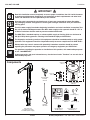
IMPORTANT
Read this installation manual completely to ensure proper installation, then file it with the owner
or maintenance department. Compliance and conformity to drain requirements and other local
codes and ordinances is the responsibility of the installer.
Separate parts from packaging and make sure all parts are accounted for before discarding
any packaging material. If any parts are missing, do not begin installation until you obtain the
missing parts.
Flush the water supply lines before beginning installation and after installation is complete. Test
the unit for leaks and adequate water flow. Main water supply to the eyewash should be “ON” at
all times. Provisions shall be made to prevent unauthorized shutoff.
The ANSI Z358.1 standard requires an uninterruptible supply of flushing fluid at a minimum 30
PSI (0.21 MPa) flowing pressure. Flushing fluid should be tepid per ANSI Z358.1.
The inspection and testing results of this equipment should be recorded weekly to verify proper
operation. This equipment should be inspected annually to ensure compliance with ANSI Z358.1.
Workers who may come in contact with potentially hazardous materials should be trained
regarding the placement and proper operation of emergency equipment per ANSI Z358.1.
For questions regarding the operation or installation of this product, visit www.bradleycorp.com
or call 1-800-BRADLEY.
Product warranties and parts information may also be found under ”Products” on our web site at
www.bradleycorp.com.
Installation
THIS
SIDE
UP
Packing List
•
•
•
•
P.O. BOX 309, MENOMONEE FALLS, WI 53052-0309 USA
TEL: 1-800-BRADLEY FAX: (262-251-5817)
http://www.bradleycorp.com
114-051
Components
P.O. BOX 309, MENOMONEE FALLS, WI 53052-0309 USA
TEL: 1-800-BRADLEY FAX: (262-251-5817)
http://www.bradleycorp.com
114-052
Signed
Signed
Signed
Date
Date
Date
Signed
Unterschrift
Signe
Date
Datum
Date
P.O. Box 309, Menomonee Falls, WI 53051
R
TEST THIS UNIT EACH WEEK
Test-operate valve(s) each week and sign below.
Report any malfunctions immediately.
Ventil(e) wöchentlich im Testbetrieb prüfen, bestätigt
durch Unterschrift. Jegliche Störung sofort melden.
DIESES GERÄT 1ST WÖCHENTLICH ZU PRÜFEN.
ESSAI HEBDOMADAIRE
Test le fonctionnement des valves chaque semaine et
signe en bas. S'il y à quelque chose qui ne va pas fait
un rapport immédiatement.
Prepack S45-1535
Safety Sign
114-052 (qty. 2)
Hook
151-001 (qty. 2)
Emergency Tag
204-421
Hex Nut #10-24
151-001 (qty. 2)
Screw #10-24 x 1/2"
160-245 (qty. 2)
Wire Nut
P10-111 (qty. 2)
Pull Rod
128-156G
Eye/Face Wash
Assembly
S05-153
Optional Stainless
Steel Showerhead Kit
S24-189
Plastic Showerhead Kit
S24-188
Heat Trace Unit
S19-300T (top supply)
S19-300B (bottom supply)
11.1
Parts List
Item 11
11.12
11.11
11.2
11.21
11.1
Parts List
Item 11

3
Installation S19-300T, S19-300B
Bradley Corporation • 215-1082 Rev. F; ECN 08-521 9/26/08
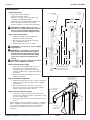
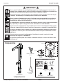
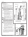
Installation
Supplies Required:
• (3) 3/8" floor anchors and bolts
• Teflon tape and pipe sealant
• Piping to 1-1/4" NPT water supply inlet on unit
with adequate supply pipe supports
• Minimum 4" drain to accommodate 30 gallons per
minute discharge for drench shower waste
• Electrical supplies to connect to unit junction box
IMPORTANT: Bottom supply units have
provisions for supporting the top of the unit.
The 1-1/4" NPT solid pipe protruding from
the shell must be used to support the unit.
Step 1: Secure unit to floor
1. Install three suitable anchors (supplied by
installer) for 3/8" bolts in the floor.
2. Bolt the base to the floor anchors using 3/8"
bolts (supplied by installer).
3. Install the pull rod to the unit as shown.
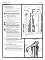
IMPORTANT: Do not rely on unit to support
supply piping.
IMPORTANT: Unit requires a minimum 30
GPM to operate and a minimum 30 PSI of
flowing water pressure. Preferred flowing
water pressure is 40-60 PSI. Water supply
to the unit must be freeze-protected (by
others).
IMPORTANT: Pipe size should be no smaller
than 1-1/4" (supplied by installer).
Step 2: Connect water supply
1. Connect the water supply piping to the 1-1/4"
NPT inlet on the unit (piping by installer).
Use pipe hangers or other means to provide
adequate supports for the supply pipe (supports
by installer).
2 Open water supply lines and test for leaks and
adequate water flow.
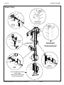
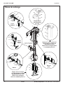
Step 3: Assemble components
1. Install the showerhead to the unit as shown. The bottom
edge of the showerhead should be 85-1/4” (2165mm)
from the floor.
2. Mount the safety signs to the wall or to the unit if
desired. Use the screws, nuts and hooks provided to
hang the signs back-to-back on the unit.
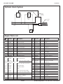
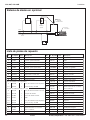
Step 4: Connect electrical supply
1. Connect the power to the junction box on the unit as
shown in the schematic on page 4 (junction box accepts
3/4" NPT conduit fittings).
2. Connect the optional alarm system and indicator light as
shown.
NOTE: Average power consumption of the unit is .7 amp/80
watts at 120VAC (.35 amp/80 watts at 220/240 vac) at 50°F
(10°C) internal unit temperature. Refer to the installation
instructions provided with the alarm system for more
information.
Use tefl on tape
only with plastic
showerheads.
Bottom supply units
must use this pipe for
supporting unit.
Safety signs
shown mounted
back-to-back.
3/4" NPT
Junction Box
opening
Ø 9" (229mm) Flange with
(3) Ø 3/8" (10mm) Holes on
a Ø 8" (203mm) Bolt Circle
Bottom Supply
1-1/4" NPT
6"
(152mm)
Top Supply
1-1/4" NPT
Junction Box 3/4"
NPT Hub
43"
(1089mm)
39-1/2"
(1004mm)
60-3/4"
(1543mm)
85-1/4"
(2165mm)
94-5/8"
(2405mm)
35-1/2"
(900mm)
68"
(1724mm)
25-3/4"
(654mm)
37-3/4"
(959mm)
92"
(2337mm)
19-1/4"
(489mm)
(245mm)
9-3/4"

4
S19-300T, S19-300B Installation
9/26/08 Bradley Corporation • 215-1082 Rev. F; ECN 08-521
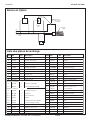
Repair Parts List
1 131-059 1 Base
2 219-029 1 Shell - Lower Left
3 219-030 1 Shell - Lower Right
4 219-027 1 Shell - Upper Left
5 219-028 1 Shell - Upper Right
6 269-1292 as req’d. Edge Trim
7 269-1289 1 Junction Box
8 269-1294 1 Pipe Plug, 3/4"
9 269-1286 1 Thermostat
10 S45-1535 1 Hardware Prepack
11 S24-188 1 Plastic Showerhead
11.1 S24-187 1 Flow Control Assembly, 23 GPM
11 S24-189 1 Stainless Steel Showerhead Assy.
11.1 S24-193 1 Shroud Assembly
11.11 187-053 1 Showerhead Shell
11.12 154-147 1 Ring
11.2 S24-188 1 Plastic Showerhead Assembly
11.21 S24-187 1 Flow Control Assembly, 23 GPM
12 269-1288 1 Connection Nipple
13 S27-301 1 Ball Valve, 1" with Nut
13.1 110-214 1 Jam Nut only
14 140-720 1 Stop Bracket
15 161-036 4 Hex Nut, 5/16"-18
16 128-153 1 Handle
17 S21-068 1 Operating Stem
18 128-150 1 Handle
19 142-002DC 2 Lockwasher
20 128-156G 1 Pull Rod, 26"
21 S05-153 1 Eyewash Assembly
21.1 S05-152 1 Yoke, Drilled
21.2 S05-135 2 Eyewash Head
21.3 S53-063 2 Dust Cover, Tethered
21.4 113-1191 1 Stem
21.5 169-1069 1 Elbow
22 S27-302 2 Ball Valve, 1/2" with Nut
22.1 110-215 2 Jam Nut only
23 153-372R 2 Ball Valve Adapter - R. H.
24 128-151 2 Handle Adapter
25 128-149 2 Flag Handle - R.H.
26 114-049 2 Handle Label
27 S89-025 1 Hose
28 119-228 1 Valve, Freeze-Protect
29 119-229 1 Valve, Scald-Protect
30 269-1296 2 Hose Barb
31 269-1285 as req’d. Rubber Tubing
Item Part No. Qty Description Item Part No. Qty Description
Optional Alarm System
Optional
Indicator
Light
Thermostat
Ground
Screw-in
Junction Box
Power
White
Black
Green
Heat Trace
Cable
Plastic Showerhead
Stainless Steel Showerhead

5
Installation S19-300T, S19-300B
Bradley Corporation • 215-1082 Rev. F; ECN 08-521 9/26/08
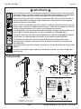
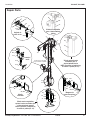
Repair Parts
18
13
14
20
16
15
15
19
13.1
17
23
24
17
25, 26
22
22.1
15
19
15
23
27
24
17
25, 26
22
22.1
15
15
19
28
30
31
30
31
29
21.1
21.2
21.3
21.4
21.5
4
11
5
6
Specify required
length when ordering
10
8
2
3
1
9
7
Pull Rod
Assembly
Eye/Face
Wash
Flag
Handle
Optional
Drench Hose
Freeze and Optional Scald Valve
(for top supply)
NOTE: Specify required length
for Item 31 when ordering.
Optional Scald Valve
(for bottom supply)
NOTE: Specify required length
for Item 31 when ordering.
29
30
31
Freeze Valve for
bottom supply.
12
28
27

6
S19-300T, S19-300B Installation
9/26/08 Bradley Corporation • 215-1082 Rev. F; ECN 08-521
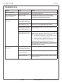
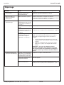
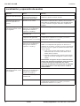
Troubleshooting
Problem Cause Solution
Low water flow at drench
shower and eyewash
Insufficient pressure
Undersized supply piping
Minimum 30 GPM required
Increase pressure/pipe size
Low water flow at drench
shower or eye wash
Debris in system Disassemble the showerhead, clean and reassemble
Unscrew the eyewash heads from the yoke, clean and
reassemble. If still clogged, replace the heads.
Freeze-protection valve is
flowing water
Power supply is off [if the
water temperature from the
valve is below 45°F (7°C)]
Turn the power on.
Water supply is too cold Make sure the unit is supplied with tempered water.
Defective thermostat [if the
water temperature from the
valve is below 45°F (7°C)]
Check continuity and replace if check fails activates at 50°F
(10°C) (factory-set).
Defective freeze valve [if the
water temperature from the
valve is above 45°F (7°C)]
Replace the freeze valve
NOTE: A water supply that is at least 45°F (7°C) or colder will
hold the freeze bleed valve open. To close the valve:
1. turn the water off temporarily or plug the valve until the
heat trace unit’s heat warms the valve
2. increase the surface temperature of the valve to above
45°F (7°C) by immersing the valve in hot water
IMPORTANT: Make sure that the heat trace unit is
operating properly before plugging the freeze bleed valve.
A plugged valve will not provide backup freeze protection
should the heat trace unit fail.
Scald-protection valve is
flowing water
Defective scald valve [if the
water temperature from the
valve is below 80°F (27°C)]
Replace the scald valve.
Direct sunlight or high
ambient temperature
Cool the unit.
Defective thermostat Check continuity and replace if check fails activates at 50°F
(10°C) (factory-set).
Page is loading ...
Page is loading ...
Page is loading ...
Page is loading ...
Page is loading ...

12
S19-300T, S19-300B Installation
9/26/08 Bradley Corporation • 215-1082 Rev. F; ECN 08-521
IMPORTANTE
Lea en su totalidad este manual de instalación para garantizar una instalación adecuada. Una vez que termine
la instalación, entregue este manual al propietario o al Departamento de Mantenimiento. Es responsabilidad de
quien instale el equipo cumplir con los códigos para desagüe y otra códigos y ordenanzas locales.
Separar todas las piezas del material de embalaje y asegurarse que todas las piezas estén incluídas antes de
desechar cualquier material de embalaje. Si faltase alguna pieza, no intentar instalar la unidad combinada
Bradley hasta obtener las piezas faltantes.
Aclarar el conducto del suministro de agua antes y después de la instalación. Verificar que no haya fugas y que
el flujo de agua sea adecuado. El suministro principal de agua a la unidad debe estar siempre en posición “ON”
(abierto). Se deben tomar medidas a fin de evitar el corte no autorizado del suministro.
La norma ANSI Z358.1 exige un suministro ininterrumpido del líquido de enjuague a una presión mínima de 30
psi (0.21 MPa). El líquido de limpieza debe estar tibio en conformidad con la norma ANSI Z358.1.
Este equipo se debe inspeccionar, probar y anotar semanalmente para mantener un funcionamiento adecuado.
Se debe revisar este equipo anualmente para asegurarse de que cumpla con la norma ANSI Z358.1.
Los trabajadores que puedan tener contacto con materiales potencialmente peligrosos deben recibir
capacitación sobre la ubicación y operación adecuada de los equipos de emergencia en conformidad con la
norma ANSI Z358.1.
Para consultas sobre la operación o instalación de este producto, visite www.bradleycorp.com o llame al 1-800-
BRADLEY.
Las garantías del producto se pueden encontrar e n “Información del producto” o en nuestro sitio Web, www.
bradleycorp.com.
Installation
T
H
IS
S
ID
E
U
P
Packing List
•
•
•
•
P.O. BOX 309, MENOMONEE FALLS, WI 53052-0309 USA
TEL: 1-800-BRADLEY FAX: (262-251-5817)
http://www.bradleycorp.com
114-051
Componentes
P.O. BOX 309, MENOMONEE FALLS, WI 53052-0309 USA
TEL: 1-800-BRADLEY FAX: (262-251-5817)
http://www.bradleycorp.com
114-052
Signed
Signed
Signed
Date
Date
Date
Signed
Unterschrift
Signe
Date
Datum
Date
P.O. Box 309, Menomonee Falls, WI 53051
R
TEST THIS UNIT EACH WEEK
Test-operate valve(s) each week and sign below.
Report any malfunctions immediately.
Ventil(e) wöchentlich im Testbetrieb prüfen, bestätigt
durch Unterschrift. Jegliche Störung sofort melden.
DIESES GERÄT 1ST WÖCHENTLICH ZU PRÜFEN.
ESSAI HEBDOMADAIRE
Test le fonctionnement des valves chaque semaine et
signe en bas. S'il y à quelque chose qui ne va pas fait
un rapport immédiatement.
Prepack S45-1535
Safety Sign
114-052 (qty. 2)
Hook
151-001 (qty. 2)
Emergency Tag
204-421
Hex Nut #10-24
151-001 (qty. 2)
Screw #10-24 x 1/2"
160-245 (qty. 2)
Wire Nut
P10-111 (qty. 2)
Pull Rod
128-156G
Eye/Face Wash
Assembly
S05-153
Optional Stainless
Steel Showerhead Kit
S24-189
Plastic Showerhead Kit
S24-188
Heat Trace Unit
S19-300T (top supply)
S19-300B (bottom supply)
11.1
Art. 11
11.12
11.11
11.2
11.21
11.1
Art. 11
Unidad de control térmico
S19-300T (abastecimiento superior)
S19-300B (abastecimiento inferior)
Lavador de ojos/rostro
S05-153
Varilla de tiro
128-156G
Cabezal de ducha de
plastico
S24-188
Cabezal de ducha de
acero inox (opcional)
S24-189
Paquete S45-1535
Letero de seguridad
114-052 (cant 2)
Gancho
151-001 (cant 2)
Tuerca para hilos
P10-111 (cant 2)
Etiqueta de
emergencia
204-421
Tuerca hexagonal n˚ 10–24
161-025 (cant 2)
Tornillo n˚ 10–24 x 1/2"
160-245 (cant 2)
Page is loading ...
Page is loading ...
Page is loading ...
Page is loading ...
-
 1
1
-
 2
2
-
 3
3
-
 4
4
-
 5
5
-
 6
6
-
 7
7
-
 8
8
-
 9
9
-
 10
10
-
 11
11
-
 12
12
-
 13
13
-
 14
14
-
 15
15
-
 16
16


Bradley S19-300B Installation guide
- Type
- Installation guide
- This manual is also suitable for
Ask a question and I''ll find the answer in the document
Finding information in a document is now easier with AI
in other languages
- français: Bradley S19-300B Guide d'installation
- español: Bradley S19-300B Guía de instalación
Related papers
-
Bradley S19-300T Installation guide
-
-
-
-
-
-
-
-
-
Other documents
-
 T & S Brass & Bronze Works EW-7656-WC Datasheet
-
Bradley Smoker S19-220BPT User manual
-
Bradley Corporation S19-125SFMBF Installation guide
-
-
-
Rocstor Y1RB006-B1 Installation guide
-
-
-
-
