Page is loading ...

DE
EN
2
WIKA operating instructions models TIF50, TIF52
14009686.04 12/2016 EN/DE
Further languages can be found at www.wika.com.
© 06/2011 WIKA Alexander Wiegand SE & Co. KG
All rights reserved. / Alle Rechte vorbehalten.
WIKA
®
is a registered trademark in various countries.
WIKA
®
ist eine geschützte Marke in verschiedenen Ländern.
Prior to starting any work, read the operating instructions!
Keep for later use!
Vor Beginn aller Arbeiten Betriebsanleitung lesen!
Zum späteren Gebrauch aufbewahren!
Operating instructions models TIF50, TIF52
Page 3 - 34
Betriebsanleitung Typen TIF50, TIF52
Seite 35 - 66

WIKA operating instructions models TIF50, TIF52
3
EN
14009686.04 12/2016 EN/DE
Contents
Contents
Declarations of conformity can be found online at www.wika.com.
1. General information 4
2. Safety 5
3. Specifications 9
4. Design and function 10
5. Transport, packaging and storage 11
6. Commissioning, operation 12
7. Electrical connection 18
8. Menu guidance of the user interface 23
9. Information on mounting and operation in hazardous areas 28
10. Maintenance and cleaning 30
11. Faults 30
12. Dismounting, return and disposal 32
Appendix 1: EU declaration of conformity 33
Appendix 2: ATEX/IECEx installation drawing 34

4
WIKA operating instructions models TIF50, TIF52
EN
14009686.04 12/2016 EN/DE
1. General information
■
The field temperature transmitters with HART
®
indication module described in these
operating instructions have been designed and manufactured using state-of-the-art
technology. All components are subject to stringent quality and environmental criteria
during production. Our management systems are certified to ISO 9001 and ISO 14001.
■
These operating instructions contain important information on handling the instrument.
Working safely requires that all safety instructions and work instructions are observed.
■
Observe the relevant local accident prevention regulations and general safety
regulations for the instrument‘s range of use.
■
The operating instructions are part of the product and must be kept in the immediate
vicinity of the instrument and readily accessible to skilled personnel at any time.
■
Skilled personnel must have carefully read and understood the operating instructions,
prior to beginning any work.
■
The manufacturer‘s liability is void in the case of any damage caused by using the
product contrary to its intended use, non-compliance with these operating instructions,
assignment of insufficiently qualified skilled personnel or unauthorised modifications to
the instrument.
■
The general terms and conditions contained in the sales documentation shall apply.
■
Subject to technical modifications.
■
Further information:
- Internet address: www.wika.de / www.wika.com
- Relevant data sheet: TE 62.01
- Application consultant: Tel.: +49 9372 132-0
Fax: +49 9372 132-406
E-mail: [email protected]
Explanation of symbols
WARNING!
... indicates a potentially dangerous situation which can result in serious injury or
death if not avoided.
CAUTION!
... indicates a potentially dangerous situation which can result in light injuries or
damage to the equipment or the environment if not avoided.
Information
… points out useful tips, recommendations and information for efficient and
trouble-free operation.
1. General information

WIKA operating instructions models TIF50, TIF52
5
EN
14009686.04 12/2016 EN/DE
DANGER!
...identifies hazards caused by electric power. Should the safety instructions not
be observed, there is a risk of serious or fatal injury.
WARNING!
... indicates a potentially dangerous situation in the hazardous area that can
result in serious injury or death, if not avoided.
2. Safety
WARNING!
Before mounting, commissioning and operation, make sure that the field
instrument is suitable for the application.
Non-observance can result in serious injury and/or damage to the equipment.
WARNING!
This is protection class 3 equipment for connection at low voltages, which
are separated from the power supply or voltage by greater than AC 50 V or
DC 120 V. Preferably, a connection to an SELV or PELV circuit is recommended;
alternatively protective measures from HD 60346-4-41 (DIN VDE 0100-410).
Alternatively for North America:
The connection can be made in line with “Class 2 Circuits” or “Class 2 Power
Units” in accordance with CEC (Canadian Electrical Code) or NEC (National
Electrical Code).
Further important safety instructions can be found in the individual chapters of
these operating instructions.
2.1 Intended use
The models TIF50 and TIF52 field instruments are universal transmitters, configurable
via HART
®
protocol, for use with resistance thermometers (RTD), thermocouples (TC),
resistance and voltage sources as well as potentiometers. They comprise a temperature
transmitter, display/operating unit and field case.
The instrument has been designed and built solely for the intended use described here,
and may only be used accordingly.
1. General information / 2. Safety

6
WIKA operating instructions models TIF50, TIF52
EN
14009686.04 12/2016 EN/DE
The technical specifications contained in these operating instructions must be observed.
Improper handling or operation of the instrument outside of its technical specifications
requires the instrument to be taken out of service immediately and inspected by an
authorised WIKA service engineer.
If the instrument is moved from a cold into a warm environment, the formation of
condensation may result in the instrument malfunctioning. Before putting it back into
operation, wait for the instrument temperature and the room temperature to equalise.
The manufacturer shall not be liable for claims of any type based on operation contrary to
the intended use.
2.2 Personnel qualification
WARNING!
Risk of injury if qualification is insufficient!
Improper handling can result in considerable injury and damage to equipment.
■
The activities described in these operating instructions may only be carried
out by skilled personnel who have the qualifications described below.
■
Keep unqualified personnel away from hazardous areas.
Skilled personnel
Skilled personnel are understood to be personnel who, based on their technical training,
knowledge of measurement and control technology and on their experience and
knowledge of country-specific regulations, current standards and directives, are capable of
carrying out the work described and independently recognising potential hazards.
Special operating conditions require further appropriate knowledge, e.g. of aggressive
media.
2.3 Additional safety instructions for instruments per ATEX
WARNING!
Non-observance of these instructions and their contents may result in the loss
of explosion protection.
WARNING!
Do not use field instruments with any damage to the exterior!
CAUTION!
■
Repairs are strictly prohibited.
■
Do not use displays presenting externally visible damage.
■
Observe the instructions for mounting and operation as well as the require-
ments for the use of the devices in hazardous areas.
2. Safety

WIKA operating instructions models TIF50, TIF52
7
EN
14009686.04 12/2016 EN/DE
2.4 Special hazards
WARNING!
Observe the information given in the applicable type examination certificate and
the relevant country-specific regulations for installation and use in hazardous
areas (e.g. IEC/EN 60079-14, NEC, CEC). Non-observance can result in serious
injury and/or damage to the equipment.
For further important safety instructions for instruments with ATEX approval, see
chapter 9 “Information on mounting and operation in hazardous areas”.
WARNING!
For hazardous media such as oxygen, acetylene, flammable or toxic gases or
liquids, and refrigeration plants, compressors, etc., in addition to all standard
regulations, the appropriate existing codes or regulations must also be followed.
WARNING!
To ensure safe working on the instrument, the operating company must ensure
■
that suitable first-aid equipment is available and aid is provided whenever
required,
■
that the operating personnel are regularly instructed in all topics regarding
work safety, first aid and environmental protection, and know the operating
instructions, in particular the section on safety instructions.
WARNING!
When working during a running process operation, measures to prevent
electrostatic discharge from the connecting terminals should be taken, as a
discharge could lead to temporary corruption of the measured value.
Only use the field instrument for earthed thermometers! The connection of a
resistance thermometer (e.g. Pt100) to the TIF5x must be made with shielded
cable. The shield must be electrically connected to the housing of the grounded
thermometer.
The connection of a thermocouple sensor to the TIF5x must be made with a
screened cable. The shield must be electrically connected with the housing of
the grounded thermometer and, additionally, grounded to the side of the TIF5x.
It should be ensured that there is equipotential bonding on installation, so that
no balancing current can flow via the shield. Here, in particular, the installation
regulations for hazardous areas should be followed!
2. Safety

8
WIKA operating instructions models TIF50, TIF52
EN
14009686.04 12/2016 EN/DE
DANGER!
Danger of death caused by electric current
Upon contact with live parts, there is a direct danger of death.
■
The instrument may only be installed and mounted by skilled personnel.
■
Operation using a defective power supply unit (e.g. short circuit from the
mains voltage to the output voltage) can result in life-threatening voltages at
the instrument!
WARNING!
Residual media in the dismounted instrument can result in a risk to persons, the
environment and equipment. Take sufficient precautionary measures.
2.5 Labelling, safety marking
Product label for whole instrument
Model
Serial number
Further approval logos
Warning note
Approval-related data + logos
Year of manufacture
Information on version (output signal, measuring range...)
Before mounting and commissioning the instrument, ensure you read
the operating instructions!
2. Safety

WIKA operating instructions models TIF50, TIF52
9
EN
14009686.04 12/2016 EN/DE
3. Specifications
3. Specifications
Specifications Model TIF50 Model TIF52
Display principle LCD, rotatable in 10° steps
Display measured value 7-segment LCD, 5-digit, character size 9 mm
Bar graph 20-segment LCD
Information line 14-segment LCD, 6-digit, character size 5.5 mm
Status indicators
♥
: HART
®
mode (signalling of HART
®
parameter adoption)
: Unit lock
: Warnings or error messages
Indication range -9999 ... 99999
Measuring rate 4/s
Accuracy ±0.1 % of the
measuring span
±0.05 % of the measuring span
Temperature coefficient ±0.1 % of the measuring span/10 K
Permissible maximum
current
100 mA
Voltage drop < DC 3 V (< DC 2 V at 20 mA); supply via current loop
HART
®
functionality
■
Access control - Secondary master
■
Automatically set
parameters
Unit, measuring range
■
Available commands - Unit, measuring range start/end, format,
zero point, span, damping, polling address
■
Identified commands Generic mode:
1, 15, 35, 44
Generic mode:
0, 1, 6, 15, 34, 35, 36, 37, 44
■
Multidrop Not supported Measured values are automatically taken
from the HART
®
digital data and displayed
EMC directive EN 61326 emission (group 1, class B) and interference immunity
(industrial application) as well as per NAMUR NE21
Ambient conditions Models TIF50, TIF52
Ambient temperature -60
1)
/ -40 ... +85 °C
Functional area of the display
-20
2)
... +70 °C
Vibration resistance 3 g per EN 60068-2-6
Shock resistance 30 g per EN 60068-2-27
1) Special version on request (only available with selected approvals)
2) In previous ambient temperatures < -20 °C a delayed recovery of the indication function could be expected, especially in
case of low loop current.

10
WIKA operating instructions models TIF50, TIF52
EN
14009686.04 12/2016 EN/DE
Field case
Material
■
Aluminium, window in polycarbonate
■
Stainless steel, window in polycarbonate
Colour Aluminium: night blue, RAL 5022
Stainless steel: silver
Cable glands 3 x M20 x 1.5 or 3 x ½ NPT
Ingress protection IP66
Weight Aluminium: approx. 1.5 kg
Stainless steel: approx. 3.7 kg
Dimensions see drawing
For further specifications see WIKA data sheet TE 62.01 and the order documentation.
When using other indicators or transmitters, their EU declarations of conformity
are valid.
The group and class of the noise emission and interference immunity, electrical
specifications and ambient temperature range can be found in the respective
data sheets and instruction manuals.
For further important safety instructions for operation in hazardous areas, see
chapter 9 “Information on mounting and operation in hazardous areas”.
4. Design and function
4.1 Description
The field instruments are used for converting a resistance value or a voltage value into a
proportional current signal (4 ... 20 mA). Thus the sensors are permanently monitored for
their fault-free operation.
The field instruments meet the requirements of:
■
Explosion protection (depending on the version)
■
Electromagnetic compatibility in accordance NAMUR recommendation NE21
■
Signalling at the analogue output in accordance with NAMUR recommendation NE43
■
Sensor burnout signalling in accordance with NAMUR recommendation NE89
(corrosion monitoring sensor connection)
Versions
Model TIF5x-F Field instrument, Ex protection (flameproof enclosure)
Model TIF5x-I Field instrument, Ex protection (intrinsically safe)
Model TIF5x-S Field instrument, no Ex protection (standard)
3. Specifications / 4. Design and function

WIKA operating instructions models TIF50, TIF52
11
EN
14009686.04 12/2016 EN/DE
4.2 Dimensions in mm (aluminium and stainless steel)
The field instrument consists of a model T32 temperature transmitter with integrated
indication and operating module, models DIH5x-B or DIH5x-Z.
4.3 Operation in safety-related applications
The field temperature transmitters models TIF50, TIF52 are suitable for use in
safety-related applications.
4.4 Scope of delivery
Cross-check the scope of delivery with the delivery note.
5. Transport, packaging and storage
5.1 Transport
Check the instrument for any damage that may have been caused by transport.
Obvious damage must be reported immediately.
5.2 Packaging
Do not remove packaging until just before mounting.
Keep the packaging as it will provide optimum protection during transport (e.g. change in
installation site, sending for repair).
5.3 Storage
Permissible conditions at the place of storage:
■
Storage temperature: -40 ... +85 °C
■
Humidity: 35 ... 85 % r. h. (non-condensing)
1556707.01
4. Design and function / 5. Transport, packaging and storage

12
WIKA operating instructions models TIF50, TIF52
EN
14009686.04 12/2016 EN/DE
Avoid exposure to the following factors:
■
Direct sunlight or proximity to hot objects
■
Mechanical vibration, mechanical shock (putting it down hard)
■
Soot, vapour, dust and corrosive gases
6. Commissioning, operation
In hazardous areas, only use field instruments that are approved for those
hazardous areas. The approval is marked on the product label.
6.1 Operating modes
The following operating modes are possible:
■
Transmitter + HART
®
slave display (TIF50)
■
Transmitter + HART
®
master display (TIF52)
6.1.1 Operating mode: HART
®
slave (model DIH50)
The digital indicators powered via the same current loop as the corresponding transmitters
monitor permanently the HART
®
communication. When modifying the unit or measuring
range of the connected transmitter, the unit of the digital indicator and the corresponding
indication range are adapted automatically.
However, it is required that the unit set in the transmitter is also set in the devices.
A flashing ♥ symbol is shown on the display when a HART
®
communication takes place for
the first time and the digital indicators are thus switched to the HART
®
mode. The ♥ symbol
is displayed permanently when the HART
®
communication is terminated and the digital
indicator is configured according to the measuring range and the unit of the connected
transmitter.
After the power supply was interrupted or the digital indicator was set manually, the ♥
symbol is no longer displayed.
During operation in the basic mode, the ♥ symbol is not displayed.
CAUTION!
The instruments react only to the HART
®
standard commands 15 and 35. If
a connected HART
®
transmitter is configured by means of other commands,
automatic setting is not possible!
The HART
®
function, i.e. the automatic adaptation of the display to the confi-
gured data of the transmitter, requires a HART
®
communication between the
transmitter and the HART
®
software (e.g. WIKA_T32) or between the transmit-
ter and the field communicator (e.g. FC375/FC475, MFC4150 etc.).
5. Transport, packaging ... / 6. Commissioning, operation

WIKA operating instructions models TIF50, TIF52
13
EN
14009686.04 12/2016 EN/DE
6.1.2 Operating mode: HART
®
master (model DIH52)
The master mode enables the modification of the measuring range, the unit, the format,
the damping and the polling address of the connected HART
®
transmitter. Further
modifications to the configuration of the transmitter (e.g. selection of the sensor) are not
possible.
During the starting procedure, the field displays try to contact the connected HART
®
transmitter in the master mode and to apply its settings (unit and measuring range). During
the connection establishment, the status line shows the message "Connecting HART
®"
.
When a HART
®
sensor is detected, the HART
®
symbol is displayed. The field indicator
switches to the HART
®
mode and starts operation using the settings received from the
transmitter. This procedure is repeated whenever the power supply is switched on.
When pressing any key during the starting process or the device has not detected any
HART
®
transmitter during approx. 70 seconds, the digital indicator switches to the basic
mode and starts operation on the basis of the factory settings.
6.2 Configuration
For configuration of the field instrument a software (e.g. WIKA_T32) or a HART
®
communicator is necessary.
The following parameters can all be configured: sensor model, sensor connection, user
measuring range, output limit, alarm indication, terminal voltage monitoring, sensor break
monitoring, measuring range monitoring, measuring rate, damping, write protection, offset
values (1-point correction), TAG no. and user linearisation (custom characteristic curve).
Furthermore, a linear transformation of the process value is possible using a 2-point
correction.
User linearisation:
Via software, customer-specific sensor characteristics can be stored in the transmitter in
order to define other sensor types. Number of auxiliary points: min. 2; max. 30. If more than
2 sensors are connected (dual sensor function) further configurations can be carried out.
With the dual sensor function, two identical sensors (resistance sensor or thermocouple)
with the same measuring range are connected and then processed together.
The field instruments are delivered with a basic configuration (see data sheet TE 62.01) or
configured according to customer specifications. If the configuration is changed afterwards,
the modifications must be noted on the label using a water-resistant felt-tip pen.
A simulation of the input value is not required to configure the TIF5x. A sensor
simulation is only required for the functional test. For model TIF52 unit und
measuring range can be configured via operating unit.
6. Commissioning, operation

14
WIKA operating instructions models TIF50, TIF52
EN
14009686.04 12/2016 EN/DE
Freely programmable sensor functionality when 2 sensors have been connected
(dual sensor)
Sensor 1, sensor 2 redundant:
The 4 … 20 mA output signal delivers the process value of sensor 1. If sensor 1 fails, the
process value of sensor 2 is output (sensor 2 is redundant).
Average value:
The 4 … 20 mA output signal delivers the average value from sensor 1 and sensor 2. If one
sensor fails, the process value of the working sensor is output.
Minimum value:
The 4 ... 20 mA output signal delivers the lower of the two values from sensor 1 and sensor
2. If one sensor fails, the process value of the working sensor is output.
Maximum value:
The 4 ... 20 mA output signal delivers the higher of the two values from sensor 1 and
sensor 2. If one sensor fails, the process value of the working sensor is output.
Difference:
The 4 ... 20 mA output signal delivers the difference of the two values from sensor 1 and
sensor 2. If one sensor fails, an error signal will be activated.
Configurable monitoring functionality
Monitoring of the measuring range:
If this function is activated, an error is signalled on the current loop (< 3.6 mA) if the
measured value is either below or over the limits of the measuring range.
Configurable monitoring functionality with 2 sensors connected (dual sensors)
The following options are not available in the differential mode!
Redundancy/hot backup:
In the case of a sensor error (sensor-break, wire resistance too high or measured value
outside the measuring range of the sensor) of one of the two sensors, the process value
will be the value from the working sensor only. Once the error is rectified, the process value
will again be based on the two sensors, or on sensor 1.
Ageing control (sensordrift monitoring)
An error signal on the output is activated if the value of the temperature difference between
sensor 1 and sensor 2 is higher than a set value, which can be selected by the user.
This monitoring only generates a signal if two valid sensor values can be determined and
the temperature difference is higher than the selected limit value. (Cannot be selected for
the 'Difference' sensor function, since the output signal already indicates the difference
value).
6. Commissioning, operation

WIKA operating instructions models TIF50, TIF52
15
EN
14009686.04 12/2016 EN/DE
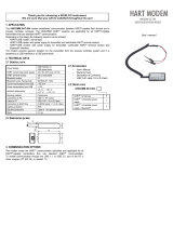
6.2.1 Configuration via the PC
To configure the transmitter, both configuration software and a HART
®
modem are needed.
WIKA offers 3 different models of HART
®
modem for this.
HART
®
modem with USB interface, model 010031,
Order no. 11025166
HART
®
modem with RS-232 interface, model 010001,
Order no. 7957522
Bluetooth HART
®
modem, ATEX, CSA, FM approved, model 010041
Order no. 11364254
The HART
®
modem can be used together with the mentioned configuration
software (see below "Configuration software WIKA_T32").
Configuration software WIKA_T32
The use of the WIKA_T32 configuration software is recommended. This is constant-
ly updated and adapted to T32 firmware enhancements. Thus full access to all the
transmitter‘s functionality and parameters is always ensured.
Further configuration software
With the following software tools it is also possible to carry out configurations at the T32 e.g.:
■
AMS and SIMATIC PDM (T32_EDD)
■
FieldMate, PACTware, SmartVision and Fieldcare (DTM_T32)
■
DTM in FDT frame application
With any other HART
®
configuration tool the generic mode functionalities can be operated
(e.g. measuring range or TAG no.).
Further information on the configuration of the T32 with the software tools
mentioned above is available on request.
6. Commissioning, operation

16
WIKA operating instructions models TIF50, TIF52
EN
14009686.04 12/2016 EN/DE
6.2.2 DD version
The model TIF5x field instrument can be operated with the following DTM or DD versions.
T32 HART
®
instrument revision Corresponding DD
(Device description)
T32 HART
®
DTM
0 Dev v0, DD v2 DTM 1.0.2
1 Dev v1, DD v1 DTM 1.0.2
2 Dev v2, DD v1 DTM 1.0.2
3 Dev v3, DD v1 DTM 2.0.0.175
6.2.3 HART
®
communicator (HC275, FC375, FC475, MFC4150)
With the HART
®
communicator the instrument functions are selected via various menu
levels and with the help of a special HART
®
function matrix (see chapter 6.4 “HART
®
configuration tree”).
6.3 Connecting FSK modem, HART
®
communicator
WARNING!
■
The measuring circuit must have a load of at least 250 Ω.
■
For all transmitters observe chapter 9 “Information on mounting and operation
in hazardous areas”.
This resistance is already integrated into the instrument for most of the power supplies
available and, thus, not required. In most of the cases, a special connection exists for the
FSK modem.
6. Commissioning, operation

WIKA operating instructions models TIF50, TIF52
17
EN
14009686.04 12/2016 EN/DE
1. PV LSL
2. PV USL
3. PV Min span
4. Custom Sensor
5. Custom Sensor
type
6. Custom Sensor
name
7. Custom Sensor
date
1. DEVICE
SETUP
5. REVIEW
1. TEST DEVICE
2. Loop test
3. CALIBRATION
4. TA DRAG
POINTER
5. Set error direction
1. STATUS
2. Self test
3. Reset
1. PV
2. PV Sensor unit
3. PV Sensor s/n
4. SENSOR
INFORMATION
5. Sensor selection
6. Sensor type
7. Sensor connection
8. Linearization mode
9. Input Temp.offset
2W offset
CJC SETTINGS
Ptx 0°C resistance
5. DEVICE
INFORMATION
2. PV
3. AO1
4. PV % range
5. PV LRV
6. PV URV
7. Elect
temperature
8. CJC
temperature
4. DETAILED
SETUP
3. BASIC
SETUP
2. DIAG/
SERVICE
1. PROCESS
VARIABLES
1. Tag
2. Set output range
3. Sensor selection
4. PV Sensor unit
5. PV Damping
6. PV Sensor s/n
1. PV
2. PV % range
3. AO1
4. CJC temperature
4. ERROR
CONDITIONING
3. OUTPUT CON-
DITION
2. SIGNAL
CONDITION
1. SENSORS
1. PROCESS
SENSORS
2. ELECT TEMP
1. PV Damping
2. Set output range
3. PV % range
1. ANALOG
OUTPUT
2. HART OUTPUT
1. Alarm level values
2. Set error direction
3. Range error active
1. Set output range
2. Input Temp.
offset
3. D/A trim
1. Ta high
2. Ta low
3. Reset recorded
Ta value
1. Elect temp
2. Ta max
3. Ta min
4. Ta Drag Pointer
1. AO1
2. Output limits
3. Loop test
4. D/A trim
1. Poll addr
2. Num req pre-
ambles
3. Burst mode
4. Burst option
1. Distributor
2. Model
3. Type code
4. Dev id
5. Tag
6. Date
7. Write protection
8. Write protect T32
9. Change password
Descriptor
Message
Final assembly
number
REVISION #'S
1. CJC temp
2. Cjc mode
3. Cjc fixval
4. Cjc Temp.offset
1. Universal rev
2. Fld dev rev
3. Software rev
4. Hardware rev
5. FW Version
6. Commissioning, operation
6.4 HART
®
configuration tree

18
WIKA operating instructions models TIF50, TIF52
EN
14009686.04 12/2016 EN/DE
7. Electrical connection
WARNING!
Observe the safety-relevant maximum values for the connection of the power
supply and the sensors defined in chapter 9.1 “Model overview and their
approvals”.
When working on the field instruments (e.g. installation/removal, maintenance work) take
measures to prevent electrostatic discharge from the terminals.
WARNING!
Carry out mounting work only with power disconnected!
Use the recommended cables and tighten the cable gland. Lead the connecting cable
downward before of the cable gland in order to provide additional protection of the device
against penetration of liquids. Rain water and condensed water can thus drip.
The device is connected by means of a commercially available two-wire cable without
screen. If electromagnetic interference exceeding the test values of EN 61326 for industrial
areas is to be expected or the HART
®
multidrop mode is used, a screened cable must
be used. Use cables with round cross section. An outside diameter of cable of 5 ... 9 mm
(0.2 … 0.35 inch) guarantees the tightness of the cable gland. When using other diameters
or cross sections, the gasket must be replaced or a suitable cable gland must be used.
Connect the cable screen on both sides to earth potential if a screened cable is required.
Connect the screen in the sensor directly to the internal earth terminal. The external earth
terminal of the case must be connected with low impedance to the equipotential bonding.
CAUTION!
If equipotential bonding currents are to be expected, a ceramic capacitor (e.g.
1 nF, 1,500 V) must be used for the connection on the evaluation side. The
low-frequency equipotential bonding currents are thus suppressed, but the
high-frequency interference signals remain.
7. Electrical connection

WIKA operating instructions models TIF50, TIF52
19
EN
14009686.04 12/2016 EN/DE
7.1 Sensor
Open the case cover, push one of the two black fastening clips backwards and
pull the display module upwards.
Designation of terminal connectors
7.1.1 Resistance thermometer (RTD) and resistance sensor
The connection of a resistance thermometer (e.g. per EN 60751) into a 2-, 3- or 4-wire
sensor connection or the connection of two identical resistance thermometers into a 2-wire
connection with an identical measuring range. The sensor input of the transmitter has to
be configured in accordance with the actually used sensor connection type, otherwise a
complete use of the possibilities of connection compensation is not possible; furthermore
this may cause additional measuring errors (see chapter 6.2 “Configuration”).
7.1.2 Thermocouples (TC)
It is possible to connect one or two identical thermocouples. Make sure that the
thermocouple is connected with the correct polarity. If the lead between the thermocouple
and the transmitter needs to be extended, only use thermal or compensation cable
appropriate for the connected thermocouple type.
1
2 3
4
1
2 3
4
1
2 3
4
Resistance thermometer/
resistance sensor
in
4-wire 3-wire 2-wire
Potentio-
meter
Thermocouple
CJC with external
Pt100
Input resistance sensor, thermocouple
11234547.0X
Dual
thermocouple/
dual mV sensor
Dual resistance
thermometer/dual
resistance sensor
in
2+2-wire
Identical dual sensors are supported for all sensor
models, i. e. dual sensor combinations as for example
Pt100/Pt100 or thermocouple type K/ type K are possible.
A further rule is:
Both sensor values have the same unit and the same
sensor range.
Sensor 1
Sensor 2
Sensor 1
Sensor 2
1
2 3
4
7. Electrical connection

20
WIKA operating instructions models TIF50, TIF52
EN
14009686.04 12/2016 EN/DE
Configure the input of the transmitter appropriately for the thermocouple type and the cold
junction compensation actually used, otherwise measurement errors may be caused (see
chapter 6.2 “Configuration”).
Should the cold junction compensation be operated with an external resistance
thermometer (2-wire connection), connect this to terminals and .
7.1.3 Voltage source
Make sure that the mV sensor is connected with the correct polarity.
7.1.4 Potentiometer
Connection of a potentiometer is possible.
7.2 Power supply, 4 ... 20 mA current loop
The model TIF5x field instrument is a 2-wire temperature transmitter; depending on the
version, it can be supplied with various types of power supply. Connect the positive pole of
the power supply to the terminal marked with ⊕ and the negative pole of the power supply
to the terminal marked with ⊖.
With flexible leads we recommend the use of crimped connector sleeves.
The integrated reverse polarity protection (wrong polarity on the terminals ⊕ and ⊖)
prevents the transmitter from damage. The following maximum values are applicable:
■
Model TIF5x-S: DC 42 V
■
Model TIF5x-I: DC 29 V
■
Model TIF5x-F: DC 30 V
The model TIF5x field instrument requires a minimum terminal voltage of DC 13.5 V. The
load must not be too high as, otherwise, in the case of relatively high currents, the terminal
voltage at the transmitter will be too low.
The model TIF5x field instrument is equipped with terminal voltage monitoring (“under-
voltage” detection). If too small a voltage is detected at the terminal (< 13.5 V) the error is
signalled on the output (< 3.6 mA).
7. Electrical connection

WIKA operating instructions models TIF50, TIF52
21
EN
14009686.04 12/2016 EN/DE
Maximum permissible load depending on the supply voltage:
Load diagram
For the power supply, use an energy-limited electrical circuit (EN/UL/IEC 61010-1,
section 8.3) using the following maximum values for the power supply:
for U
B
= 42 V (DC): 5 A
For the external power supply a separate switch is required.
The power supply is connected at the front via the Philips screws of the display
module. Connect the positive pole of the power supply to the terminal marked
with ⊕ and the negative pole of the power supply to the terminal marked with ⊖.
The signal line of the transmitter is to be connected to the terminal blocks inside the field
case. To do so, connect the positive pole of the signal line to the terminal marked with ⊕
(red cable) and the negative pole of the signal line to the terminal marked with ⊖ (black
cable).
With flexible leads we recommend the use of crimped
connector sleeves.
The integrated reverse polarity protection (wrong
polarity on the terminals ⊕ and ⊖) prevents the digital
indicator from damage.
11289130.02
Ex ia
1239
1152
717
456
0
0 13,5 24 30 40 42
Voltage U
B
in V
Load R
A
in Ω
DIH50-B
Non-hazardous area Ex area
Transmitter
red
black
Voltage supply
Load
7. Electrical connection
/