Page is loading ...

Logic HE
™
Log Range
Balanced Flue
PR2756 Issue 4 (August 2019)
Instructions for Use, Installation & Servicing
For use in GB & IE (Great Britain & Republic of Ireland).
THE OUTER CASING, FRONT AND GLASS PANEL BECOME EXTREMELY HOT DURING OPERATION AND
WILL RESULT IN SERIOUS INJURY AND BURNS IF TOUCHED. IT IS THEREFORE RECOMMENDED THAT A
FIREGUARD COMPLYING WITH BS 8423 (LATEST EDITION) IS USED IN THE PRESENCE OF YOUNG
CHILDREN, THE ELDERLY OR INFIRM.
This product contains a Heat resistant glass panel. This panel should be checked during Installation and at each servicing interval. If any
damage is observed on the front face of the glass panel (scratches, scores, cracks or other surface defects), the glass panel must be
replaced and the appliance must not be used until a replacement is installed. Under no circumstances should the appliance be used if any
damage is observed, the glass panel is removed or broken.
It is essential that ALL of the screws that retain the glass frame are replaced and tightened correctly. Under no circumstances should the
appliance be operated if any of these screws are loose or missing.
These Instructions must be left with the appliance for future reference and for consultation when servicing the appliance. Please make the
customer aware of the correct operation of the appliance before leaving these instructions with them.
The commissioning sheet found on Page 3 of this Instruction manual must be completed by the Installer prior to leaving the premises.
IMPORTANT

2
Appliance Commissioning Checklist ......................3
User Instructions .......................................................4
Installation Instructions ..........................................14
Technical Specification ............................................................. 14
Site Requirements .................................................................... 17
Installation ................................................................................20
Commissioning ......................................................................... 29
Servicing Instructions .............................................30
Fault Finding .............................................................................30
How to replace parts ................................................................ 34
Basic spare parts list ............................................................... 42
Service Records ....................................................................... 46
Information Requirements.........................................................47
Logic HE Balanced Flue
Contents
Covering the following models:
To receive your Extended Warranty your Gazco appliance must have
been purchased from our Expert Retailer Network and registered within
one month of purchase or installation. Please note that all warranties
are effective from the date of purchase. Any Gazco product purchased
outside of our Extended Retailer Network, or not registered within the
stated time will carry a standard 12 month warranty.
It is a condition of the Extended Warranty that the installation
complies with the relevant Building Regulations and is carried out
by a suitably trained and qualified individual (GasSafe in the UK or
equivalent in other countries) with the certificate of installation and the
Commissioning Report on Page 3 completed and retained by the end
user.
Full terms and conditions are detailed in the Warranty Statement on
the Gazco website www.gazco.com. In the event of any conflict of
information the wording on the website shall prevail.
Important Note: Should any problems be experienced with your
product, claims must first be submitted to the Expert Retailer where
the appliance was purchased from who will offer immediate assistance
or contact Gazco on your behalf.
It is a requirement of the Building Regulations 2010 that the installation of this appliance is notified to the Local Authority. It is
the responsibility of the GasSafe registered installer to carry out this notification to the Local Authority via the GasSafe register
Competent Persons Scheme in England and Wales (different rules apply in Scotland and Northern Ireland).
When the installation has been notified, GasSafe will send a Building Regulations Compliance Certificate to you containing
details of the work completed. Please ensure that the person responsible for the installation of this appliance completes this
notification and records it in the Appliance Commissioning Checklist on page 3.
IT IS YOUR RESPONSIBILITY TO COMPLY WITH THE BUILDING REGULATIONS AND BE ABLE TO PRODUCE THIS
CERTIFICATE SHOULD IT BE REQUIRED IN THE FUTURE.
Gas Type
LoGic He Bf
Remote Control Slide Control
Nat Gas 101-014 101-281
LpG 101-666 101-516

3
To assist us in any guarantee claim please complete the following information:-
Appliance Commissioning Checklist
FLUE CHECK
PASS FAIL
1. Flue Is correct for appliance
2. Flue ow Test
3. Spillage Test
GAS CHECK
1. Gas soundness & let by test
2. Standing gas pressure mb
3. Appliance working pressure (on High Setting)
Minimum Pressure Requirement: NG - 17.5mbar LPG - 34.5mbar
NB All other gas appliances must be operating on full
mb
4. Gas rate m
3
/h
5. Does Ventilation meet appliance requirements
SAFETY CHECK
1. Check soundness of the Thermocouple connections - including tightness and lead integrity
2. Glass checked to ensure no damage, scratches, scores or cracks
3. Glass frame secured correctly and all screws replaced
BUILDING CONTROL NOTIFICATION
YES NO
1. Installer notied GasSafe/Local Authority of installation via Competent Persons Scheme?
Retailer ...............................................
.......................................................
.......................................................
Contact No. ...........................................
Date of Purchase .....................................
Model No. ............................................
Serial No. .............................................
Gas Type .............................................
Installation Company ................................
......................................................
......................................................
Engineer. . . . . . . . . . . . . . . . . . . . . . . . . . . . . . . . . . . . . . . . . . . . .
Contact No. ..........................................
GasSafe Reg No. ....................................
Date of Installation ..................................
RETAILER AND INSTALLER INFORMATION
IMPORTANT NOTICE
Explain the operation of the appliance to the end user, hand the completed instructions to them for safe keeping,
as the information will be required when making any guaranteed claims.

4
Welcome
Congratulations on purchasing your Logic HE fire, if installed
correctly Gazco hope it will give you many years of warmth
and pleasure for which it was designed.
The purpose of this manual is to familiarise you with your
appliance, and give guidelines for its installation, operation
and maintenance. If, after reading, you need further
information, please do not hesitate to contact your Gazco
retailer.
WARNING
In the event of a gas escape or if you can smell
gas, please take the following steps:
• Immediately turn off the gas supply at the
meter/emergency control valve
• Extinguish all sources of ignition
• Do not smoke
• Do not operate any electrical light or power
switches (On or Off)
• Ventilate the building(s) by opening doors
and windows
• Ensure access to the premises can be made
Please report the incident immediately to the
National Gas Emergency Service Call Centre on
0800 111 999 (England, Scotland and Wales),
0800 002 001 (N. Ireland) or in the case of LPG,
the gas supplier whose details can be found on
the bulk storage vessel or cylinder.
The gas supply must not be used until remedial
action has been taken to correct the defect and
the installation has been recommissioned by a
competent person.
1. General
1.1 Installation and servicing must only be carried out by a
competent person whose name appears on the GasSafe
register. To ensure the engineer is registered with GasSafe
they should possess an ID Card carrying the following logo:
1.2 In all correspondence, please quote the appliance type and
serial number, which can be found on the data badge.
1.3 Do not place curtains above the appliance:
You must have 300mm clearance between the appliance
and any curtains at either side.
1.4 No furnishings or other objects should be placed within
1 metre of the front of the appliance.
1.5 If a shelf is fitted, a distance of 300mm above the appliance
opening is required.
1.6 If any cracks appear in the glass panel do not use the
appliance until the panel has been replaced.
1.7 Do not obstruct the flue terminal in any way, i.e. by planting
flowers, trees, shrubs etc. in the near vicinity, or by leaning
objects against the terminal guard.
1.8 Do not put any objects on the terminal guard; it will lose its
shape.
1.9 If you use a garden sprinkler, do not let quantities of water
into the flue terminal.
1.10 This product is guaranteed for 5 years from the date of
installation, as set out in the terms and conditions of sale
between Gazco and your local Gazco retailer. Please
consult with your local Gazco retailer if you have any
questions. In all correspondence always quote the Model
Number and Serial Number.
IMPORTANT: NEVER position a television or
screen above this appliance.
Operating the Appliance
There are 2 types of control systems available for this
appliance:
Section 2. Manual and Remote Control
Section 3. Slide Control
Follow the relevant section for specific operation.
2. Manual and Remote Control
There are two ways of lighting the appliance:
2a. Using the Manual Controls on the Control Box (located
on the appliance.
2b. By thermostatic remote control.
2a. Manual Operation (Control Box)
2a.1 The manual controls are located on the Control Box at the
bottom of the appliance, behind the ash cover,
see Diagram 1.
1
User Instructions

5
User Instructions
2a.2 There are a series of buttons on the left hand side of the
Control Box, see Diagram 2.
2
Power Switch
Power Button
Flame Adjustment (Up)
Flame Adjustment (Down)
To operate the appliance the white Power Switch on the
Control Box must be switched ON.
Note: The white Power Switch does not need to be
turned off each time the appliance is not in use.
However, if the appliance is left unattended for long
periods of time (e.g. vacation), it is recommended
to place the Power Switch into the off position.
Turning the appliance on:
2a.3 Press and hold the Power Button for 1 second and release.
The burner will light within 2 seconds.
2a.4 Use + and - buttons to adjust the flame height between
Minimum and Maximum.
Turning the appliance off
2a.5 Press the power button to turn the appliance off.
IMPORTANT: YELLOW FLAMES TYPICALLY
APPEAR WHEN THE APPLIANCE HAS REACHED
NORMAL OPERATING TEMPERATURE. THIS CAN
TAKE UP TO 30 MINUTES.
WARNING: IF THE APPLIANCE FAILS TO LIGHT OR
BECOMES EXTINGUISHED IN USE, WAIT 3
MINUTES BEFORE ATTEMPTING TO RELIGHT.
THE APPLIANCE MAY TAKE SEVERAL AUTOMATIC
ATTEMPTS TO RESTART.
DO NOT INTERRUPT THE VALVE DURING THIS
PROCESS.
2b. Remote Control
To operate the appliance the white Power Switch on the
Control Box must be switched ON.
To activate the Remote Control it will be necessary
to cradle the handset to unlock, see Diagram 3.
The green light will illuminate to show the handset
is ready to use.
IMPORTANT: Continue to cradle the handset
throughout an operation to keep it unlocked.
If the green light goes off during an operation it
will be necessary to reposition the handset so the
light comes back on and restart the operation.
3
Handset unlocked
(when illuminated)
Handset Features
4
Battery status
Light Sensor
(for display light)
Day of the week
Appliance Status
Time (12 hour or
24 hour display)
Program Mode
Room
Temperature
Mode:
Man (Manual)
Zzz (Timer)
Thermostat or
Timed
In Range of appliance
(missing if not in or
appliance turned off).
Handset unlocked
(when illuminated)
Change Handset
Settings
Change Mode
Settings
Decrease Button
Increase Button
Power Button
The Icon at the bottom of the screen displays the battery
condition of both the batteries in the handset and in the
Control Box alternatively.
RC = Remote Control Handset and FC = Fire Control
(Control Box).
If the handset has been replaced or the fire has
been serviced, see Installation Section 11b to set
up the handset.

6
Manual Operation (Remote Control)
To activate the Remote Control it will be necessary
to cradle the handset to unlock, see Diagram 3.
The green light will illuminate to show the handset
is ready to use.
IMPORTANT: Continue to cradle the handset
throughout an operation to keep it unlocked.
If the green light goes off during an operation it will
be necessary to reposition the handset so the light
comes back on and restart the operation.
Turning the appliance on
2b.1 Press the Power Button until Pilot flashes on the display.
2b.2 Release the Power Button and the Flame symbol will
appear on the display.
If the button is held the command will be cancelled for
safety reasons.
2b.3 Holding the handset to unlock, use + and - buttons to adjust
the flame height between Minimum and Maximum.
Turning the appliance off
2b.4 Holding the handset to unlock, press the power button to
turn the appliance off.
IMPORTANT: YELLOW FLAMES TYPICALLY
APPEAR WHEN THE APPLIANCE HAS REACHED
NORMAL OPERATING TEMPERATURE. THIS CAN
TAKE UP TO 30 MINUTES.
WARNING: IF THE APPLIANCE FAILS TO LIGHT OR
BECOMES EXTINGUISHED IN USE, WAIT 3
MINUTES BEFORE ATTEMPTING TO RELIGHT.
THE APPLIANCE MAY TAKE SEVERAL AUTOMATIC
ATTEMPTS TO RESTART.
DO NOT INTERRUPT THE VALVE DURING THIS
PROCESS.
Setting Timer Mode (in Manual operation)
Timer Mode will turn the appliance off after a set period of time has
elapsed.
Timer Mode can be set before or during manual operation of the
fire.
Note: If Timer mode is activated and the fire is
manually turned off, the timer will be cancelled.
Changes to the Timer will reset to the default time
on next use.
If the fire is off when the Timer mode is set then the
timer will automatically start when the fire is turned
on.
2b.5 Hold the handset to unlock and press and release the
MODE button. The word MAN and the Zzz symbols flash at
the top of the display.
2b.6 Press and release the SET button.
This will activate the Timer mode.
User Instructions
The default time period is 1 hour, unless altered in
2b.39.
2b.7 Pressing the SET button again will show the remaining time.
This can be altered by pressing the + or - buttons.
The timer can be set between 1 minute and 24 hours.
2b.8 After adjusting the time press SET again to confirm the time
setting desired.
Once the countdown has reached zero the fire will turn off.
Thermostatic Mode
The handset contains a thermostatic sensor to control the
operation of the appliance according to the temperature of the
room.
There are 3 temperature options that can be set:
Day Mode - indicated by a Sun symbol on the display
(default temperature 24ºC)
Night Mode - indicated by a Moon symbol on the display
(default temperature 18ºC)
Frost Protection - indicated by a Snowflake symbol on the
display (default temperature 5ºC)
Programming the Modes
2b.9 Holding the handset to unlock, press and hold the SET
button until a beep is heard to indicate the command has
been received.
2b.10 Release the SET button. PROG and a flashing thermometer
symbol will be displayed at the top of the display.
2b.11 Press and release the SET button to enter Day Mode.
The current temperature setting and mode will be displayed-
for example the Sun symbol on the left shows it is in Day
Mode and the default temperature is 24ºC.
2b.12 To change the temperature press + or - whilst the set
temperature is displayed to alter the setting.
2b.13 Press and release the SET button to confirm and to scroll to
the Night Mode.
2b.14 To change the temperature press + or - whilst the set
temperature is displayed to alter the setting.
2b.15 Press and release the SET button to confirm and to scroll to
Frost Protection mode.
2b.16 To change the temperature press + or - whilst the set
temperature is displayed to alter the setting.
2b.17 When finished press the SET button again and the new
settings will be accepted.
The display will return to the time of day screen.
Choosing a Mode
When choosing a mode during operation the
temperature can be temporarily changed, however these
settings will reset to the previously set programmed
settings when the fire is turned off.
2b.18 Holding the handset to unlock, press and release the MODE
button several times until a thermometer symbol flashes at
the top of the display.

7
User Instructions
2b.19 Press the SET button to enter the Thermostatic mode.
2b.20 Press the Set button again to see the current temperature
setting and mode - for example the a Sun symbol on the left
shows it is Day Mode and the default temperature is 24.
2b.21 With the temperature displayed, press + or - to alter the
setting.
2b.22 Press the MODE button repeatedly to scroll through the
settings and to select Night mode or Frost Protection.
The handset must be left in the chosen mode for it to
operate.
2b.23 When finished press SET again and the new setting will be
accepted.
The display will return to the time of day screen.
If at any time the power button is operated during Thermostatic
Mode the control will cancel any thermostat operation and return
the handset to Manual Mode.
Setting Timer Mode (in Thermostatic Operation)
Timer Mode will turn the appliance off after a set period of time has
elapsed.
Timer Mode can be set before or during thermostatic operation of
the fire.
2b.24 Hold the handset to unlock, press and release the MODE
button until the word MAN and the Zzz symbols are flashing
at the top of the display.
2b.25 Press and release the SET button.
This will activate the Timer mode.
The default time period is 1 hour, unless altered in
2b.39.
2b.26 Pressing the SET button again will show the remaining
Time.
This can be altered by pressing the + or - buttons.
The timer can be set between 1 minute and 24 hours.
2b.27 After adjusting the time press SET again to confirm the time
setting desired.
Once the countdown has reached zero the fire will turn off.
Note: If Timer mode is activated and the fire is
manually turned off, the timer will be cancelled.
Changes to the Timer will reset to the default time
on next use.
If the fire is off when the Timer mode is set then the
timer will automatically start when the fire is turned
on.
Setting the Clock
To adjust the time on the handset after initial set up:
Holding the remote to keep the green light on and the
handset unlocked:
2b.28 Press and hold the SET button until a beep is heard to
indicate the command has been received.
2b.29 Release the SET button. PROG will be displayed at the top
left of the display.
2b.30 Press the MODE button twice until SET UP flashes in the
top right of the display.
2b.31 Press and release the SET button. The handset will display
an H:24, see Diagram 5.
5
24 denotes a 24 hour clock and 12 denotes a 12 hour clock.
2b.32 Press the + or - button on the handset to toggle between the
two settings.
Press the SET button to confirm and progress to setting the
day of the week.
Setting the Day of the Week
2b.33 Press and release the + and - buttons until the correct day
of the week is shown on the display.
6
Mo = Monday, Tu = Tuesday, We = Wednesday, Th = Thursday,
Fr = Friday, Sa = Saturday and Su = Sunday.
2b.34 Press SET to confirm the day of the week and progress to
setting the time.

8
Setting the Hour
2b.35 Press and release the + or - button to change the hour to
the correct hour. Press SET to confirm and progress to
setting the minute.
7
Setting the Minutes
2b.36 Repeat the process to change the minutes.
Setting the Temperature Display (Celsius or Fahrenheit)
2b.37 Press and release the + or - button to toggle between C and
F. When the display shows the desired symbol, press and
release the SET button to store.
8
2b.38 To enter Advanced Settings, see below. To finish, place the
handset down and wait until the home screen is displayed
and the unlock light goes off.
ALL THE NECESSARY SETTINGS REQUIRED HAVE
NOW BEEN COMPLETED. ANY FURTHER
FUNCTIONS ON THIS HANDSET ARE FOR
FACTORY SETTING AND NOT TO BE USED.
The Handset is now ready to operate the appliance.
Advanced Menu Settings
It is possible to change additional preset settings of the control
features.
2b.39 Follow steps 2b.28 to 2b.38 to access the Advanced Menu
Settings. Press and release the SET button to enter the
Advanced Settings Menu.
Advanced Settings are:
Back Light (L)
- A = Automatic (default setting).
The backlight comes on in the dark.
- O = Light never comes on.
- 1 = Light comes on when the handset is unlocked.
User Instructions
Display Contrast (C)
- 8 Levels from 0 - 7 (Default level 4).
P = Pairing with devices other than the Control Box.
This feature is not available on this appliance.
IMPORTANT: THE FURTHER FUNCTIONS ON THIS
HANDSET ARE FOR FACTORY SETTING ONLY
AND ARE NOT TO BE USED.
PLACE THE HANDSET ON A FLAT SURFACE AND
WAIT UNTIL THE HOME SCREEN IS DISPLAYED
AND THE UNLOCK LIGHT TURNS OFF.
Paging the Handset
If the handset is lost it can be located by pressing the + only on the
Control Box for 5 seconds.
The handset will flash and make a noise for 60 seconds to indicate
where it is.
Pick up the Handset and cradle it to unlock. The flashing and noise
will stop.
If the handset is not discovered in 60 seconds the process will
need to be repeated.
Changing the Default Timer Mode
It is possible to change the default time period for the Timer mode.
The default time period for Timer mode is factory set to
1 hour.
To change the default time:
Holding the remote to keep the green light on and the
handset unlocked:
2b.40 Press and hold the SET button until a beep is heard to
indicate the command has been received.
2b.41 Release the SET button. PROG will be displayed at the top
left of the display.
2b.42 Repeatedly press the MODE button until the Zzz symbol
flashes at the top of the display.
2b.43 Press and release the SET button.
2b.44 Press the + or - buttons to alter the default time period.
The timer can be set between 1 minute and 24 hours.
2b.45 After adjusting the time press SET again to confirm.
Note: This does not activate the Timer mode, see
Installation Section, Manual Operation or Thermostatic
Mode.

9
User Instructions
3. Slide Control
This appliance is operated using the slide control on the top
right hand side of the decorative front.
When the appliance is OFF the slide control will be at the
highest point, see Diagram 9.
9
OFF
Ignition Point
Low Setting
High Setting
Lighting the Pilot
3.1 Push the slide control down as far as possible to its lowest
point, see Diagram 8, this is the ignition point.
Keep the slide control pressed down for 5 seconds to
ensure the pilot is lit. Then release.
The appliance should light on its lowest setting.
3.2 When released the slide control automatically raises to a
natural stop point, see Diagram 9.
Repeat the above steps if the appliance does not light.
3.3 If, after repeating the above steps the pilot does not light,
contact your Retailer or Installer.
Adjusting the Flame height
3.4 Increase the flame height and temperature by carefully
moving the slide control up until the next stop point is felt,
see Diagram 9. This denotes the highest setting.
3.5 Carefully move the slide control down to the lower stop point
to return to the lowest setting.
IMPORTANT: YELLOW FLAMES TYPICALLY
APPEAR WHEN THE APPLIANCE HAS REACHED
NORMAL OPERATING TEMPERATURE. THIS CAN
TAKE UP TO 30 MINUTES.
WARNING: IF THE APPLIANCE FAILS TO LIGHT OR
BECOMES EXTINGUISHED IN USE, WAIT 3
MINUTES BEFORE ATTEMPTING TO RELIGHT.
Switching OFF the Appliance
3.6 To turn the appliance off lift the slide control to its highest
stop point, see Diagram 9. The pilot goes out.
4. Replacing the Appliance Batteries
Replace batteries at least every 12 months during the annual
service of the fire.
It is essential to use high quality batteries (Duracell
or equivalent) when replacing batteries.
4a. Remote Control
The icon at the bottom shows the battery condition of both the
batteries in the handset and in the Control Box alternately, see
Diagram 10.
10
Battery status
RC = Remote Control Handset and FC = Fire Control
(Control Box).
Note: Change the batteries in the handset before
they are flat, to avoid having to reprogram the time
of day in again. N.B. Pairing is not lost, even if the
batteries are removed or flat.
The appliance Control Box requires 3 AA size alkaline batteries.
The handset requires 2 AA size alkaline batteries.
4a.1 The appliance battery is located in the Control Box at the
bottom of the appliance behind the ash cover.
4a.2 Slide the white Power Switch on the Control Box to the
OFF position before attempting to change the batteries.
11
Power Switch

10
4a.3 The battery covers can be opened without tools by using a
fingernail and pressing to unhook the clip that retains the
cover, see Diagram 12.
12
Control Box
Remote Control
4a.4 The orientation of these is shown molded into the battery
compartment, see Diagram 13.
13
Remote Control
Control Box
Power Supply via Micro USB
It is possible to power the Control Box via a 5V
Micro USB connection, see Diagram 14.
If a USB lead is used batteries are not required in
the Control Box.
DO NOT CONNECT OTHER ELECTRIC DEVICES TO
THE CONTROL BOX.
4a.5 After fitting the batteries, slide the white Power Switch on
the Control Box to the ON position for the appliance to
operate, see Diagram 14.
14
Power Switch
Micro USB Port
Note: The white Power Switch does not need to be
turned off each time the appliance is not in use.
However, if the appliance is left unattended for long
periods of time (e.g. vacation), it is recommended
to place the Power Switch into the off position.
4b. Slide Control
4b.1 The battery box is located at the bottom left of the appliance
behind the ash cover, see Diagram 15.
15
9V Battery
Ignition
Unit
4b.2 Remove the old battery and replace with a new high quality
(Duracell or similar) 9V battery.
User Instructions

11
5. Cleaning the Appliance
5.1 Make sure the appliance and surrounds are cool before
trying to clean.
5.2 Refer to the separate decorative front instructions to remove
the front from the appliance.
5.3 Remove the glass frame by removing the 4 screws in the
retaining bracket, see Diagram 16.
Detail A
A
16
5.4 Tilt the top of the glass frame forward and disengage
the lower location tabs from the slots in the firebox, see
Diagram 16, Detail A. Place carefully to one side.
5.5 To clean the glass surface, Gazco recommends you use hot
soapy water.
5.6 The glass frame must be refitted to the appliance following
cleaning or servicing.
Ensure that the rope seal on the box is intact, then locate
the glass frame location tabs into the slots on the firebox,
see Diagram 16, Detail A.
5.7 Secure the glass frame using 4 screws in the retaining
bracket, see Diagram 16.
Replace ALL of the securing screws ensuring that a screw
is present in all fixing slots.
NEVER OPERATE THE APPLIANCE WHEN THE GLASS
FRAME IS REMOVED OR BROKEN.
Refer to the separate decorative front instructions to replace
the front on the appliance.
UNDER NO CIRCUMSTANCES SHOULD THE
APPLIANCE BE USED IF ANY OF THE GLASS
FRAME RETAINING SCREWS ARE LOOSE OR
MISSING.
6. Arrangement of the Fuel Bed
Advice on handling and disposal
of fire ceramics
The fuel effect and side panels of this
appliance are made from Refractory Ceramic
Fibre (RCF), a material which is commonly
used for this application.
Protective clothing is not required when
handling these articles, but we recommend you
follow normal hygiene rules of not smoking,
eating or drinking in the work area and always
wash your hands before eating or drinking.
To ensure that the release of RCF fibres are
kept to a minimum, during installation and
servicing a HEPA filtered vacuum is
recommended to remove any dust
accumulated in and around the appliance
before and after working on it. When servicing
the appliance it is recommended that the
replaced items are not broken up, but are
sealed within heavy duty polythene bags and
labelled as RCF waste.
RCF waste is classed as stable, non-reactive
hazardous waste and may be disposed of at a
licensed landfill site.
Excessive exposure to these materials may
cause temporary irritation to eyes, skin and
respiratory tract; wash hands thoroughly after
handling the material.
7. Log Layout
LOGS MUST BE POSITIONED ACCORDING TO THE
FOLLOWING INSTRUCTIONS TO GIVE THE CORRECT
FLAME EFFECT.
7.1 Ensure the burner tray is clean and free from any debris, see
Diagram 17.
Note: The LPG and Nat Gas burner trays are visually
different but the log layouts are the same.
17
Nat Gas Burner shown
User Instructions

12
7.2 Place Log A in position on the 2 locating pins,
see Diagram 18.
18
A
Nat Gas Burner shown
7.3 Spread the Lava Rock evenly over the fuel bed and around
Log A, see Diagram 19.
Ensure that the fuel effect does not obstruct the pilot.
19
Nat Gas Burner shown
Burner Bracket
(Nat Gas only)
7.4 Log B is positioned on the right hand locating pin, and rests
against the back liner, see Diagram 20.
Nat Gas only - ensure that the left hand side rests on the
burner bracket, see Diagrams 19 & 20.
20
B
7.5 Log C rests on Log A and the front tray with the locating pin
facing up, see Diagram 21.
21
C
7.6 Log D ts onto the locating pin and rests on Log B, see
Diagram 22.
22
D
7.7 Position the 2 embers in the front right and back left corners,
see Diagram 23.
23
7.8 Sparingly spread an amount of the Embaglow bres provided
on the sections highlighted, see Diagram 24.
Take care not to use more than half a packet per
application.
WARNING - DO NOT PLACE NEAR THE PILOT AREA.
24
User Instructions

13
8. Flame Failure Device
8.1 This is a safety feature incorporated on this appliance which
automatically switches off the gas supply if the pilot goes out
and fails to heat the thermocouple.
Remote Only: In the event of flame extinction the control
will make several attempts to restart. DO NOT interrupt the
valve during this process.
IF THIS OCCURS DO NOT ATTEMPT TO RELIGHT THE
APPLIANCE FOR 3 MINUTES.
9. Running In
9.1 During initial use of a new GAZCO appliance a strong odour
will be encountered as various surface coatings become hot
for the first time. Although these odours are harmless it is
recommended that the appliance is operated on maximum
for 4 to 8 hours in order to fully burn off these coatings. After
this period the odours should then disappear.
If the odours persists, please contact your installer for
advice.
9.2 During the first few hours of burning there may be
discolouration of the flames. This will also disappear after a
short period of use.
10. Servicing
10.1 The appliance must be serviced every 12 months by a
qualified GasSafe Engineer. In all correspondence always
quote the Model number and the Serial number which may
be found on the Commissioning Checklist (Page 3).
11. Ventilation
11.1 This appliance requires no additional ventilation.
12. Installation Details
12.1 Your installer should have completed the commissioning
sheet at the front of this book. This records the essential
installation details of the appliance. In all correspondence
always quote the Model number and Serial number.
13. Hot Surfaces
13.1 Parts of this appliance become hot during normal use.
13.2 Regard all parts of the appliance as a working surface,
except for the control access panel and the slider handle
(slide control model only).
13.3 Provide a suitable fire guard to protect young children and
the infirm.
User Instructions

14
Installation Instructions
Technical Specification
Covering the following models:
Model
Gas
Cat.
Gas Type
Working
Pressure
Aeration Injector
Gas Rate
m
3
/hr
Input kW
(Gross)
Country
High Low
Logic HE BF
Log
Remote
I
2H
Natural Gas G20 20mbar 2 x 4mm 161 0.400 4.2 2.5 GB, IE
I
3P
Propane G31 37mbar 2 x 12mm 104 0.154 4.1 2.5 GB, IE
Logic HE BF
Log
Slide
I
2H
Natural Gas G20 20mbar 2 x 4mm 161 0.419 4.3 2.6 GB, IE
I
3P
Propane G31 37mbar 2 x 12mm 104 0.158 4.2 2.6 GB, IE
Efciency 86% Net (Class 1)
NOx Class 4
Flue Outlet Size Ø 100mm
Flue Inlet Size Ø 152mm
Gas Inlet Connection Size Ø 8mm
The net efficiency of this appliance has been measured as specified in EN613:2001 and the result after conversion to
gross using the appropriate factor from Table E4 of SAP 20012 is 79.9%. The test data has been certified by Kiwa
Nederland BV. The gross efficiency value may be used in the UK Government's Standard Assessment Procedure (SAP) for
energy rating of dwellings.
PACKING CHECKLIST
Qty Description Fixing Kit containing:
Log Version
1 x Log Set
1 x Lava Rock
1 x Instruction Manual
1 x Embaglow
1 x 1.7m Silicone Seal
4 x Wall Plugs
4 x Wood Screws
1 x 9V Battery (Slide Only)
5 x AA Battery (Remote Only)
Gas Type
LoGic He Bf
Remote Control Slide Control
Nat Gas 101-014 101-281
LpG 101-666 101-516

15
FRAMES
Box Prol2 Frame *** Arts2 Frame ***
FINISH Remote Slide Remote Slide
Matt Black 912-232 901-272 912-862 901-167
Polished Brass Effect 912-140 901-286 - -
Polished Steel Effect 912-027 901-299 - -
Brushed Steel Effect 912-358 901-310 - -
Polished Brass - - 912-508 901-194
Polished Stainless - - 912-914 901-206
Brushed Stainless - - 912-268 901-214
Installation Instructions
Technical Specification
Complete Front Options
Frame & Front Combinations
*** A Box Profil2 Frame or Arts2 Frame must be used in conjunction with an Arts, Wave, Chartwell, Holyrood or Spanish Front
FRONT Remote Slide Control
DESIGNIO 912-396, 912-018 -
DESIGNIO 2 901-493, 901-511, 901-526 901-539, 901-580, 901-643
VOGUE 901-398
BEAT 901-350
PROGRESS 912-239 -
TEMPO 912-197, 912-221, 912-316 901-385, 901-403, 901-414
WINCHESTER 8697MB + 8697HP 901-369, 901-372
DIMENSION2 912-322 -
RICHMOND 8679 -
STOCKTON 901-488
FRONTS
Arts Front Wave Front Chartwell Front Holyrood Front * Spanish Front *
FINISH All Models All Models All Models All Models All Models
Matt Black 901-425 901-024 901-159 912-020 912-083
Polished Brass Effect 901-530 901-061 901-164 912-226 912-160
Highlight Polished 901-296 901-092 901-185 912-257 912-127
Polished Chrome 901-476 901-083 901-170 912-392 912-216

16
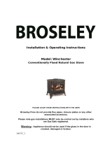
OVERALL EXTERNAL DIMENSIONS
MINIMUM AND MAXIMUM FLUE SIZE
Installation Instructions
Technical Specification
302mm
435mm
549mm
592mm
272mm
222mm
222mm
402mm
472mm
146.5mm
MINIMUM FLUE LENGTH
MAXIMUM FLUE LENGTH
68mm
262mm
5mm Gap
Flue cut to 90mm
222mm

17
1. Flue & Chimney Requirements
NOTE: This appliance can only be installed in
conjunction with the flue supplied.
You must adhere to the following:
1.1 The flue must be sited in accordance with BS5440: Part 1
(latest edition), see Diagram 1.
1.2 Fit a guard to protect people from any terminal less than 2
metres above any access such as level ground, a balcony
or above a flat roof.
Installation Instructions
Site Requirements
UK Dimensions
1
Dimension Terminal Position Minimum
Distance
A* Directly below an opening 600mm
B* Above an opening 300mm
C* Horizontally next to an opening 400mm
D Below gutters, soil pipes or drain pipe 300mm
E Below eaves 300mm
F Below balcony or car port roof 600mm
G From a vertical drain pipe or soil pipe 300mm
H From an internal or external corner or to a
boundary alongside the terminal
600mm
I Above ground, roof or balcony level 300mm
Dimension Terminal Position Minimum
Distance
J From a surface or boundary facing the
terminal
600mm
K From a terminal facing the terminal 600mm
L From an opening in the car port (e.g. door,
window) into the dwelling
1200mm
M Vertically from a terminal on the same wall 1200mm
N Horizontally from a terminal on the same
wall
300mm
P From a structure on the roof 600mm
Q Above the highest point of intersection with
the roof
300mm
* In addition, the terminal should not be nearer than 300mm to an opening in the building fabric formed for the purpose of accommodating a built-in element such as a window frame.
1.3 The flue must be securely fixed and fire precautions
followed in accordance with local and national codes of
practice.
1.4 The horizontal terminal can be reduced in length,
see Diagram 2.

18
2. Rear Flue
2
Terminal dimensions:
395 x 200 x 200 mm (H x W x D)
Guard supplied
Cut to length as required on site.
2.1 Decide on the terminal position.
2.2 Measure the height from the finished hearth level/ base of
the appliance to the centre of the required hole.
2.3 A masonry installation requires the addition of a suitable
lintel to support the opening. Refer to Installation
Instructions, Technical Information for details of the flue
length.
NOTE - Carefully consider:
a) Terminal positions
b) Flue supports
c) Weatherproofing
d) Fire precautions
For all the above options, you must conform to local and
national codes of practice.
2.4 Use only Gazco supplied flue on this appliance.
2.5 A guard (supplied) must be fitted to any terminal less than 2
metres above any access such as level ground, a balcony or
above a flat roof.
Timber Framed Buildings
2.6 It will be necessary to provide additional clearance when the
flue passes through a wall containing any combustible
materials so as to prevent a fire hazard.
2.7 The hole through which the flue will pass, must have a steel
sleeve which is positioned so that an air gap of at least
25mm is maintained between the outer surface of the flue,
and any part of the sleeve.
2.8 For further guidance on the installation of gas appliances in
timber framed buildings, contact your local buildings control
authority.
Installation Instructions
Site Requirements
3. Gas Supply
3.1 Before installation, ensure that the local distribution
conditions (identification of the type of gas and pressure)
and the adjustment of the appliance are compatible.
3.2 Ensure the gas supply delivers the required amount of gas
and is in accordance with the rules in force.
3.3 Factory-sheathed/wrapped soft copper tubing with small
ridges which allow pipe movement are considered to be a
suitable alternative to a pipe sleeve, when recessing the unit
into a cavity wall the gas supply is best fed through the wall
from the outside. Soft soldered joints can only be used
outside the appliance.
3.4 This appliance is supplied complete with a factory fitted
isolation device incorporated into the inlet connection. No
further isolation device is therefore required.
4. Ventilation
4.1 This appliance requires no additional ventilation.

19
5. Appliance Location
NOTE: It is recommended you construct the back panel
of the fireplace from natural materials cut into three or
more sections to prevent cracking. Resin-based
materials may not be suitable. This appliance is an
effective heat producer and attention must be paid to
the construction and finish of the fireplace.
5.1 This appliance must stand on a non-combustible hearth that
is at least 12mm thick.
5.2 It must be fitted into a non-combustible opening. The
minimum dimensions shall be as shown in Diagram 3.
A
B
D
F
C
E
3
Dimensions Min Max
A 420mm 450mm
B 560mm 575mm
C 230mm -
D 300mm -
E 150mm -
F 720mm 750mm
5.3 These appliances must be hearth mounted into a fireplace
opening conforming to National Standards.
5.4 If the appliance is greater than 50mm above the floor, then
no hearth is required, although due consideration should be
given to how the heat may affect the floor material.
5.5 This appliance can only be installed on an outside wall with
suitable clearances for the flue terminal and guard (if
required).
5.6 This appliance is not suitable for installation into a
combustible wall. All combustible material must be removed
from the area shown, see Diagram 5.
720
420
150
560
300
860
5
5.7 The maximum depth of combustible shelf is 150mm at a
minimum height of 300mm above the fireplace opening.
Installation Instructions
Site Requirements

20
Installation Instructions
1. Safety Precautions
1.1 For your own and other’s safety, you must install this
appliance according to local and national codes of practice.
Failure to install the appliance correctly could lead to
prosecution. Read these instructions before installing
and using this appliance.
1.2 These instructions must be left intact with the user.
1.3 Do not attempt to burn rubbish on this appliance.
1.4 Keep all plastic bags away from young children.
1.5 Do not place any object on or near to the appliance and
allow adequate clearance above the appliance.
IF THE APPLIANCE IS EXTINGUISHED OR GOES OUT IN
USE, WAIT 3 MINUTES BEFORE ATTEMPTING TO
RELIGHT THE APPLIANCE.
IMPORTANT: REFER TO DATA BADGE AND
TECHNICAL SPECIFICATION AT THE FRONT OF THE
MANUAL TO ENSURE THE APPLIANCE IS
CORRECTLY ADJUSTED FOR THE GAS TYPE AND
CATEGORY APPLICABLE IN THE COUNTRY OF USE.
FOR DETAILS OF CHANGING BETWEEN GAS
TYPES REFER TO SERVICING, SECTION 13,
REPLACING PARTS.
Unpacking
1.6 Remove the appliance from its packaging, and check that it
is complete and undamaged.
Put the loose ceramic parts to one side so that they are not
damaged during installation.
2. Installation of the Gas Supply
For specific gas types and working pressures see
Technical Specification, page 14.
TO CHANGE FROM ONE GAS TYPE TO ANOTHER A
COMPLETE ENGINE ASSEMBLY AND DATA BADGE WILL
BE REQUIRED. SEE SECTION 10 REPLACING PARTS.
2.1 Before installation, ensure that the local distribution
conditions (identification of the type of gas and pressure)
and the adjustment of the appliance are compatible. See
Technical Specification on page 14.
2.2 The position of the gas inlet pipe is shown, see Diagram 1.
35mm
120mm
1
2.3 All supply pipes must be purged of any debris that may have
entered, prior to connection to the appliance.
2.4 The gas supply enters through the silicone panel located on
the rear of the outer box. This will need to be slit with a
sharp knife prior to passing the supply pipe through.
3. Preparing the Appliance
3.1 Remove the backing from the self-adhesive silicone sealing
strip and apply to the rear flange of the firebox ensuring that
the strip is positioned as close to the outer edge as is
practically possible, see Diagram 2, Arrow A.
B
A
2
3.2 Gas pipe entry must come through the rear right-hand side
of the box. The rubber seal must be cut using a sharp knife
to allow the isolating elbow to pass through it. Ensure the
rubber is not damaged when doing this,
see Diagram 2, Arrow B.
3.3 A means of isolation is provided with the appliance. This
must be fitted to the supply pipe prior to installing the
firebox.
/