Page is loading ...

IMPORTANT
THE OUTER CASING, FRONT AND GLASS PANEL BECOME EXTREMELY HOT DURING OPERATION AND WILL RESULT IN
SERIOUS INJURY AND BURNS IF TOUCHED. IT IS THEREFORE RECOMMENDED THAT A FIREGUARD COMPLYING WITH BS
8423 (LATEST EDITION) IS USED IN THE PRESENCE OF YOUNG CHILDREN, THE ELDERLY OR INFIRM.
This product contains a Heat resistant glass panel. This panel should be checked during Installation and at each servicing interval. If any damage is observed on
the front face of the glass panel (scratches, scores, cracks or other surface defects), the glass panel must be replaced and the appliance must not be used until a
replacement is installed. Under no circumstances should the appliance be used if any damage is observed, the glass panel is removed or broken.
It is essential that ALL of the screws that retain the glass frame are replaced and tightened correctly. Under no circumstances should the appliance be operated if any of
these screws are loose or missing.
These Instructions must be left with the appliance for future reference and for consultation when servicing the appliance. Please make the customer aware of the
correct operation of the appliance before leaving these instructions with them.
The commissioning sheet found on Page 3 of this Instruction manual must be completed by the Installer prior to leaving the premises.
PR2478.8.06.2021
Balanced Flue Log Effect Stove Range
with Thermostatic Remote Control
Installation Instructions

2
Appliance Commissioning Checklist ......................3
User Instructions .......................................................4
Installation Instructions ..........................................17
Technical Specifications ...........................................................17
Site Requirements .................................................................... 18
Installation ................................................................................21
Commissioning ......................................................................... 40
Servicing Requirements .........................................41
Fault Finding .............................................................................41
How to replace parts ................................................................ 43
Spare parts list .........................................................................53
Information Requirement - Gas Heaters ................................ 56
Service Records ....................................................................... 57
Covering the following models:
CONTENTS
LOFT FREESTANDING - BALANCED FLUE
It is a requirement of the Building Regulations 2010 that the installation of this appliance is notified to the Local Authority. It is
the responsibility of the GasSafe registered installer to carry out this notification to the Local Authority via the GasSafe register
Competent Persons Scheme in England and Wales (different rules apply in Scotland and Northern Ireland).
When the installation has been notified, GasSafe will send a Building Regulations Compliance Certificate to you containing details
of the work completed. Please ensure that the person responsible for the installation of this appliance completes this notification
and records it in the Appliance Commissioning Checklist on page 3.
IT IS YOUR RESPONSIBILITY TO COMPLY WITH THE BUILDING REGULATIONS AND BE ABLE TO PRODUCE THIS
CERTIFICATE SHOULD IT BE REQUIRED IN THE FUTURE.
MODEL LOFT
Nat Gas 548-032
LPG 548-457
WARNING
In the event of a gas escape or if you can smell
gas, please take the following steps:
• Immediately turn off the gas supply at the
meter/emergency control valve
• Extinguish all sources of ignition
• Do not smoke
• Do not operate any electrical light or power
switches (On or Off)
• Ventilate the building(s) by opening doors
and windows
• Ensure access to the premises can be made
Please report the incident immediately to the
National Gas Emergency Service Call Centre on
0800 111 999 (England, Scotland and Wales) , 0800
002 001 (N. Ireland) or in the case of LPG, the gas
supplier whose details can be found on the bulk
storage vessel or cylinder.
The gas supply must not be used until remedial
action has been taken to correct the defect and
the installation has been recommissioned by a
competent person.

3
To assist us in any guarantee claim please complete the following information:-
APPLIANCE COMMISSIONING CHECKLIST
FLUE CHECK
PASS FAIL
1. Flue Is correct for appliance
2. Flue ow Test N/A
3. Spillage Test N/A
GAS CHECK
1. Gas soundness & let by test
2. Standing gas pressure mb
3. Appliance working pressure (on High Setting)
Minimum Pressure Requirement: NG - 17.5mbar LPG - 34.5mbar
NB All other gas appliances must be operating on full
mb
4. Gas rate m
3
/h
5. Does Ventilation meet appliance requirements N/A
SAFETY CHECK
1. Check soundness of the Thermocouple connections - including tightness and lead integrity
2. Glass checked to ensure no damage, scratches, scores or cracks
3. Glass frame secured correctly and all screws replaced
BUILDING CONTROL NOTIFICATION
YES NO
1. Installer notied GasSafe/Local Authority of installation via Competent Persons Scheme?
Retailer ...............................................
.......................................................
.......................................................
Contact No. ...........................................
Date of Purchase .....................................
Model No. ............................................
Serial No. .............................................
Gas Type .............................................
Installation Company ................................
......................................................
......................................................
Engineer. . . . . . . . . . . . . . . . . . . . . . . . . . . . . . . . . . . . . . . . . . . . .
Contact No. ..........................................
GasSafe Reg No. ....................................
Date of Installation ..................................
RETAILER AND INSTALLER INFORMATION
IMPORTANT NOTICE
Explain the operation of the appliance to the end user, hand the completed instructions to them for safe keeping,
as the information will be required when making any guaranteed claims.

4
GENERAL
Installation and servicing must only be carried out by a competent
person whose name appears on the GasSafe register. To ensure
the engineer is registered with GasSafe they should possess an ID
Card carrying the following logo:
In all correspondence, please quote the appliance type and serial
number which can be found on the data badge located at the rear
of the appliance or on the Commissioning Checklist on Page 3.
Do not place curtains above the appliance:
You must have 300mm clearance between the appliance and any
curtains at either side.
The manufacturer considers the full outer casing of this stove to
be a working surface and it will become hot whilst in operation. A
suitable guard is recommended to protect young children, the aged
and the inrm.
No furnishings or other objects should be placed within
1 metre of the front of the appliance.
If a shelf is fitted, a distance of 225mm above the appliance is
required.
2
3
4
1
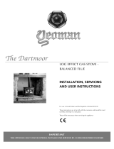
Mode Settings
See Advanced Controls
instructions
5
1
2
3
4
5
IMPORTANT: YELLOW FLAMES TYPICALLY
APPEAR WHEN THE APPLIANCE HAS REACHED
NORMAL OPERATING TEMPERATURE. THIS CAN
TAKE UP TO 30 MINUTES.
WARNING: IF THE APPLIANCE FAILS TO LIGHT OR
BECOMES EXTINGUISHED IN USE, WAIT 3
MINUTES BEFORE ATTEMPTING TO RELIGHT.
OPERATING THE APPLIANCE
Do not attempt to burn rubbish in this appliance.
This appliance must only be operated with the door secured rmly in
position. If any cracks appear in the glass the appliance must not be
used until the glass panel is replaced.
If, for any reason, the ue has to be removed from the appliance,
the seals must be replaced in the inner spigot.
Do not obstruct the ue terminal in any way i.e. by planting owers,
trees shrubs etc. in the near vicinity, or by leaning objects up
against the terminal guard.
Do not put any objects on the terminal guard; it will lose its shape.
Do not use a garden sprinkler or hose near the terminal.
This product is guaranteed for 5 years from the date of installation,
as set out in the terms and conditions of sale between Gazco and
your local Gazco retailer. Please consult with your local Gazco
retailer if you have any questions. In all correspondence always
quote the Model Number and Serial Number.

5
There are 3 different modes available for controlling and operating
the appliance:
1. Manual Mode
2. Temp Mode (Automatic)
3. Timer Mode (Automatic)
In MANUAL MODE you can:
— turn on the main burner using the UP button
— regulate the flame from high to low and back
— turn off the burner leaving just the pilot burning
In TEMP MODE (Automatic) you can:
— set the room temperature so the thermostat in the remote
automatically maintains that temperature
In TIMER MODE (Automatic) the appliance:
— turns on and off according to the set time periods
— automatically regulates the room temperature during the
set periods
NOTE: When operating the appliance in Temp or
Timer mode, the pilot remains lit and the appliance
then automatically switches on at programmed times
to bring the room to the set temperature whether or
not you are in the room.
NEVER LEAVE ANY COMBUSTIBLE MATERIALS
WITHIN 1 METRE OF THE FRONT OF THE
APPLIANCE.
SWITCHING BETWEEN MODES
Press the SET button to change to Temperature Mode.
Press again to change to Timer Mode.
Keep pressing to run through all operating modes. These
are:
— MAN
— DAY TEMP
— NIGHT TEMP
— TIMER
and back to MAN
NOTE: MAN mode can also be reached by pressing either the
UP or DOWN button.
MANUAL MODE
Press the OFF button and the UP button simultaneously. You hear
several clicks and audible beeps as the appliance begins the
ignition process, (up to 30 seconds).
Turning the appliance Off:
Press the OFF button to turn the appliance off.
FOR SAFETY, YOU MUST WAIT 30 SECONDS BEFORE
LIGHTING THE APPLIANCE AGAIN.
Increasing the Flame Height:
Press the UP button once to increase flame height one stage.
Press and hold the UP button to increase to maximum.
ADVANCED CONTROLS
Decreasing the Flame Height:
Press the DOWN button once to decrease flame height one
stage. Press and hold the DOWN button to decrease to minimum.
At the lowest point the appliance goes to 'Standby Mode' (Only
Pilot lit).
NOTE: While pressing a button a symbol indicating
transmission appears on the display. The receiver
confirms transmission with a sound signal.
TEMP MODE (AUTOMATIC)
The display shows the current room temperature.
To increase or decrease the appliance’s output:
Press the SET button to select either the DAY TEMP or the NIGHT
TEMP mode by briefly pressing the SET button.
Hold the SET button until the TEMP display flashes and then let
go.
Set the desired temperature with the UP and DOWN arrows.
(Minimum temperature 5C, maximum 40C or 40F to 99F when
Fahrenheit is the preferred option)
Press the OFF button to stop the display flashing or wait to return
to TEMP mode.
NOTE: If you set a temperature that is beneath the
current room temperature, the appliance
automatically switches to PILOT (Stand by).
If you would like the Night temperature control to turn
off then decrease the temperature until [--] is
displayed.
TIMER MODE (AUTOMATIC)
There are two programmable settings you can make over a 24
hour period, P1 and P2. These are normally used to provide an
early morning and evening setting for each working week:
P1 + = Start Timed Setting 1
P1 + = End of Timed Setting 1
P2 + = Start Timed Setting 2
P2 + = End of Timed Setting 2
P1 - Program 1 for a Timed Setting
Press the SET button until the TIMER mode is displayed.
Hold the SET button. The displays flashes the current time for P1.
While the time displayed is flashing you can alter the hours
and minutes set.
To set the time your appliance first lights, change P1
— Press the UP button to alter the hour.
— Press the DOWN button to alter the minutes in 10 minute
increments.

6
Press SET again to move to the end setting for P1 This is the
time your appliance first shuts down:
— Press the UP button to alter the hour.
— Press the DOWN button to alter the minutes.
P2 - Program 2 for a Timed Setting
Use the same steps outlined in 2.8 to change the setting for P2.
If you have already set P1 and want to alter the setting for P2 only:
— Press the SET button until TIMER mode is displayed.
— Hold the SET button until the display flashes the current
time for P1
— Press the SET button once again to scroll past the settings for
P1 and P1
With the time still flashing:
— Press the UP button to alter the hour
— Press the DOWN button to alter the minutes
Once all four times are set press the OFF button.
To view existing settings:
— Select Timer Mode
— Press and briefly hold the SET button you see the start time
for P1.
— Repeat the above step for the start and end of each program.
Low Battery
“BATT” is displayed on the remote when its batteries need
replacement.
Setting the time
Simultaneously press the up and down buttons.
Press the up button to set the hour and the down button to set the
minutes.
Press OFF to return to the manual mode or simply wait.
Setting the °C/24 Hour or °F/12 Hour clock
Press OFF and the down arrow until the display changes
from°C/24 hour clock to °F/12 hour clock and vice versa.
If the remote is removed, lost or damaged, signals
transmitted to the receiver cease. Your appliance will
go to standby (pilot) mode after 6 hours.
TROUBLESHOOTING
IMPORTANT: In the unlikely event that the handset
fails to communicate correctly with the appliance
it may be necessary to turn off the gas supply at
the isolation valve until any problems can be
resolved.
The gas meter and isolation valve can be located
outside in a meter box, under the stairs, beneath
the kitchen sink or in the garage. Whilst this list is
not exhaustive, it is important to be able to
identify the location of the valve in case of any
gas emergency.
To turn off the gas supply, simply turn the handle
so the lever is at 90 degrees to the upright gas
pipe.
If you smell gas, open doors and windows and
never operate any electrical switches.
Immediately call the Gas Emergency Services on
0800 111 999.
ADVANCED CONTROLS

7
CLEANING THE APPLIANCE
1
2
Make sure the re and surrounds are cool before cleaning.
Use:
– A dry cloth to clean the appliance casting.
– A damp cloth for the glass front.
3
4
NOTE: SUPPORT DOOR WHEN REMOVING
REPLACE ALL OF THE SECURING SCREWS,
ENSURING THAT A SCREW IS PRESENT IN ALL
FIXING SLOTS.
UNDER NO CIRCUMSTANCES SHOULD THE
APPLIANCE BE USED IF ANY OF THE GLASS
FRAME RETAINING SCREWS RE LOOSE OR
MISSING.

8
CHANGING THE APPLIANCE BATTERIES
1 2
It is essential to use high quality batteries (Duracell or
equivalent) when replacing batteries in the handset or
control box.
PLEASE ENSURE NO WIRES ARE TRAPPED
BEFORE REPLACING THE PLINTH.
THE LEAD IS EASILY DAMAGED.
3 4
4 X AAA

9
LOG LAYOUT
LOGS MUST BE POSITIONED ACCORDING TO THE FOLLOWING INSTRUCTIONS TO GIVE THE CORRECT FLAME EFFECT.
C
D
A
B
A
1
2
3

10
B
4
C
5
D
6
Embaglow
IT MAY NOT BE NECESSARY TO USE ALL THE
EMBAGLOW IN THIS PACK.
SPARINGLY SPREAD AN AMOUNT OF THE FIBRES
PROVIDED ON THE SECTIONS HIGHLIGHTED IN THE
INSTRUCTIONS.
Take care not to use more than specified in the
instructions.
WARNING:
DO NOT PLACE NEAR THE PILOT AREA.
Do not place Embaglow in the area around the pilot burner - see
highlighted example on diagram as this may effect the ignition
process and flame picture.

11
FLAME FAILURE DEVICE
This is a safety feature incorporated on this appliance which
automatically switches off the gas supply if the pilot goes out and
fails to heat the thermocouple.
IF THIS OCCURS DO NOT ATTEMPT TO RELIGHT THE
APPLIANCE FOR 3 MINUTES.
RUNNING IN
During initial use of a new Gazco appliance a strong odour will be
encountered as various surface coatings become hot for the rst
time. Although these odours are harmless it is recommended that
the appliance is operated on maximum for 4 to 8 hours in order to
fully burn off these coatings. After this period the odours should then
disappear.
If the odours persists, please contact your installer for advice.
During the rst few hours of burning there may be discolouration of
the ames. This will also disappear after a short period of use.
SERVICING AND SUPPORT
Servicing and Support
To keep your appliance looking and performing at its best, it
must be serviced annually. This service must be undertaken
by a suitably qualified individual and your retailer can organise
this for you. Alternatively, Gazco offer a manufacturers premium
service with our friendly team of qualified engineers which can
be booked at www.gazco.com/support
In all correspondence always quote the Model number and the
Serial number which may be found on the Commissioning Checklist
(Page 3).
VENTILATION
This appliance requires no additional ventilation.
INSTALLATION DETAILS
Your installer should have completed the commissioning sheet at
the front of this book. This records the essential installation details
of the appliance. In all correspondence always quote the Model
number and Serial number.
HOT SURFACES
Parts of this appliance become hot during normal use.
Regard all parts of the appliance as a ‘working surface’, except for
the access to the controls.
Provide a suitable re guard to protect young children and the inrm.

12
APPLIANCE LOCATION
Once the position of the appliance has been decided secure to the
hearth.
The non-combustible hearth must be at least 12mm thick, and
project a minimum of 50mm from the base of the appliance in all
directions.
With the exception of Wall Mounted models, the appliance is
not suitable for installation against a combustible wall.
Check minimum distances to combustible materials.
This appliance can be installed with an up and out ue (vertical wall
- horizontal ue) or with a vertical ue with roof termination.
HEARTH INSTALLATION
(NOT APPLICABLE FOR BASE SECTION INSTALLATIONS
MODELS)
Gazco recommend the hearth extends to the following dimensions.
C
A
B
DIMENSIONS A B C
All Models 716mm 498mm 12mm
BASE SECTION INSTALLATION
It is not necessary to site these products on a non-combustible floor
but the floor must be flat and solid for the appliance to be levelled
and secured in place.
This appliance may be situated anywhere in the room, but due
consideration should be taken to ensure that it is sited within the
constraints of the allowable flue configuration.
DO NOT INSTALL APPLIANCE ON A CARPET.
SECURING THE APPLIANCE TO THE WALL
(WALL MOUNTED MODELS ONLY)
WARNING: This appliance weighs 62kg.
The manufacturer has designed this appliance to
attach to a masonry wall and all xings supplied
reect this. If siting on a studwork wall, the xing
points must be through the timber stud and not
plasterboard. Use appropriate xings.
DO NOT attach solely to a plasterboard wall.
If installing on a studwork wall it is essential that the battens
are located in the xing area for the wall mounting bracket.
MOUNTING BRACKET DIMENSIONS
53
3
129
411
295
129
62
523
119
300
(Centre)
304
(Centre)
54
266
535
300
(Centre)
304
(Centre)

13
APPLIANCE LOCATION
DISTANCE FROM FLOOR / HEARTH LEVEL
It is necessary to leave a minimum gap of 100mm below
the base of the wall mounted appliance to ensure servicing
access.
MINIMUM CLEARANCE
Freestanding appliances are not suitable for installation against a
combustible wall.
(NOT APPLICABLE FOR WALL MOUNTED MODELS.)
Ensure that all minimum clearances to combustible materials
are complied with, see Diagrams.
The specied clearances provide the minimum distance to
combustible materials. If the appliance is intended to be installed
into a non-combustible opening the clearance to the sides and
above the appliance can be reduced.
However, it is recommended that the specied clearances are
maintained to allow adequate air ow and access to controls.
The clearance at the rear of the appliance must always be a
minimum of 50mm (NOT APPLICABLE FOR WALL MOUNTED
MODELS).
A
B
A
C
DIMENSION
LOFT
FREESTANDING
INSTALLATION
LOFT
WALL MOUNTED
INSTALLATION
A 150 150
B 225 400
C 50 0

14
FLUE & CHIMNEY REQUIREMENTS
Note: This appliance must only be installed with the ue supplied.
The following: must be adhered to:
The ue must be sited in accordance with BS5440: Part 1 (latest edition).
Fit a guard to protect people from any terminal less than 2 metres above any access such as level ground, a balcony or above a at roof.
All vertical and horizontal ues must be securely xed and re precautions followed in accordance with local and national codes of practice.
Two types of ue terminals are available, horizontal and vertical.
To measure for a horizontal terminal decide on the terminal position.
Measure the height from the top of the appliance to the centre of the required outlet.
For minimum and maximum ue dimensions see relevant sections.
Allow enough room either above or to the side of the appliance to assemble the ue on top.
Assemble a horizontal ue in the following order:
— Vertical section
— 90° elbow
— Horizontal plus terminal
Support the opening of a masonry installation with a lintel.
Only the horizontal terminal section can be reduced in size.
TIMBER FRAMED BUILDINGS
It will be necessary to provide additional clearance when the flue passes through a wall containing any combustible materials so as to prevent
a fire hazard.
The hole through which the flue will pass, must have a steel sleeve which is positioned so that an air gap of at least 25mm is maintained
between the outer surface of the flue, and any part of the sleeve.
For further guidance on the installation of gas appliances in timber framed buildings, contact your local buildings control authority.
GAS SUPPLY
This appliance is intended for use on a gas installation with a governed meter.
Make sure local distribution conditions (identication of the type of gas and pressure) and the adjustment of the appliance are compatible before
installation.
Ensure the gas supply delivers the required amount of gas and is in accordance with the rules in force.
Soft copper tubing can be used on the installation and soft soldered joints outside the appliance.
A factory tted isolation device is part of the inlet connection; no further isolation device is required.
All supply gas pipes must be purged of any debris that may have entered prior to connection to the appliance.
The gas supply must be installed in a way that does not restrict the removal of the appliance for servicing and inspection.
VENTILATION
The installation of this product requires no additional ventilation modications to the building.

15
406
481
369
STANDARD MODEL
137
214
770
434226
361
359
379
130
592
DIMENSIONS
This appliance has been certified for use in countries other than
those stated. To install this appliance in these countries, it is
essential to obtain the translated instructions and in some cases
the appliance will require modification. Contact Gazco for further
information.
PACKING CHECKLIST
ALL MODELS
Qty Description Fixing Kit containing:-
1 x Loft Appliance
1 x Log Set (4 Logs)
1 x Lining Set
All Models:
2 x No.8 Red Rawl Plugs
1 x Battery Holder
1 x Embaglow Packet
1 x instructions
2 x No.8 Screw
4 x AA Batteries
1 x 9v Battery
1 x 70mm Restrictor
Graphite Metal Plinth Only:
3 x M5x25 Hex Head Screws
To Extension Section Only:
4 x No.8 x 10 Screws
Stone Plinth & Log Store Only:
4 x Metal Rawl Plug
4 x No.6 x 40 Coach Screw
4 x 32mm Felt Pad

16
DIMENSIONS
WITH LOG STORE BASE
WITH TOP BOX
WITH TOP BOX AND PLINTH
WITH LOG STORE BASE AND TOP BOX
WITH PLINTH
1152
300
382
815
46
1412
1457
1793

17
TECHNICAL SPECIFICATION
MODEL
GAS
CAT.
GAS TYPE
WORKING
PRESSURE
AERATION INJECTOR
GAS RATE
M
3
/H
INPUT KW
(GROSS)
COUNTRY
HIGH LOW
Loft
Nat Gas
I
2H
G20 20mbar 8mm x 2 440 0.543 5.7 3.5
GB, IE
Loft
LPG
I
3P
G31 37mbar
No Plate
Fitted
111 0.173 4.8 2.9
Rear Exit Wall Thickness - Min 200mm/ Max 550mm
Efciency Class 1 - 94.3%
Flue Outlet Size ø 100mm, Flue Inlet Size ø 150mm
Gas Inlet Connection Size ø 8mm
The net efciency of this appliance has been measured as specied in EN613:2001 and the result after conversion to gross
using the appropriate factor from Table E4 of SAP 2012 is 84.9%. The test data has been certied by Kiwa Nederland B.V.
The gross efciency value may be used in the UK Government's Standard Assessment Procedure (SAP) for energy rating
of dwellings.
RESTRICTOR REQUIREMENT - NAT GAS/ LPG
VERTICAL & HORIZONTAL FLUE TOP EXIT - VERTICAL ONLY INCLUDING OFFSET
Vertical Flue Height Horizontal Length Restrictor Size Vertical Flue Height Restrictor Size
500mm - 999mm 250mm - 1000mm No restrictor 2000mm - 4999mm Ø 52mm
1000mm - 1499mm 250mm - 1000mm Ø 70mm 5000mm - 10,000mm Ø 47mm
1500mm - 3000mm 250mm - 5000mm Ø 60mm

18
SITE REQUIREMENTS
REAR FLUE
This ue extends horizontally from the back of the appliance.
ALL MODELS (8526)
200mm min
550mm max
Terminal dimensions:
395 x 200 x 200 mm (H x W x D)
Guard supplied
Cut to length as required on site, see Diagram.
TOP FLUE
There are two types of ue terminal: Horizontal and Vertical.
FOR HORIZONTAL TERMINAL
INSTALLATIONS:
Decide on the terminal position.
Measure the height from the top of the appliance to the centre of the
required hole. For minimum and maximum dimensions see all Up
and Out Diagrams.
To t the ue access is required to the top or the side of the
appliance to connect the ue.
Assemble the vertical sections making sure the top plate and ue
collar are tted before the ue pipe.
Add the 90° elbow.
Add the horizontal section and terminal.
Only the horizontal terminal can be reduced in size.
A masonry installation requires the addition of a suitable lintel to
support the opening. Refer to Technical Information for details of the
ue length
TOP FLUE UP AND OUT KI
T
This ue rises vertically from the top of the appliance, then
continues horizontally outward.
The basic kit comprises:
ALL MODELS (8523/8523AN)
1 x 500mm vertical length
1 x 500mm terminal length
1 x 90 degree elbow
1 x wall plate
1 x 52mm restrictor
1 x 60mm restrictor
1 x 75mm restrictor
4 x xing screw

19
SITE REQUIREMENTS
This kit provides the minimum materials. Extra lengths can be
added to the vertical and horizontal sections.
Refer to Technical Specication to identify when to use a restrictor.
TOP FLUE UP AND OUT WITH
ADDITIONAL BEND
An additional bend can be used on the horizontal section (45° or
90°) but the overall horizontal ue is reduced.
When A = 1.0 to 1.499 metres B+C = 1.0 metre max (Nat Gas - No restrictor,
LPG - 75mm Restrictor)
When A = 1.499 to 3.0 metres B+C = 4.0 metres max (Nat Gas - 70mm restrictor,
LPG - No restrictor)
EITHER 45˚
OR 90˚
TOP FLUE VERTICAL KIT
This ue is vertical from the top of the appliance, see Diagram.
A minimum vertical rise of 2m to a maximum of 10m.
999-539/999-539AN
The basic kit comprises:
2 x 1m lengths
1 x 1m terminal lengths
1 x 52mm restrictor (sliding plate assembly)
1 x 47mm restrictor (sliding plate assembly)
Extra lengths can be added.
Refer to Technical Specication to identify when to use a restrictor.
TOP FLUE VERTICAL OFFSET KIT
8530/8530AN
Used with kit 999-539. A minimum rise of 500mm is required to the
rst bend, see Diagram.

20
OPTIONAL EXTRA FLUE LENGTHS
AND BENDS
NOMINAL
LENGTH
ACTUAL
LENGTH
STAINLESS
FINISH
ANTHRACITE
FINISH
200mm 140mm 8527 8527AN
500mm 440mm 8528 8528AN
1000mm 940mm 8529 8529AN
45° Bend N/A 8507 8507AN
90° Bend N/A 8508 8508AN
Optional Flue Collar 8548MB
/