Airmar B45, B258, B260, B265LH, B265LM, B275LHW, B285HW, B285M, B744V, B744VL, B765LH, B765LM, B785M, SS260, SS505 High-Performance Fairing Owner's manual
- Type
- Owner's manual

INSTALLATION INSTRUCTIONS
17-276-01 rev. 15 07/25/18
WARNING
Installation of the anti-rotation bolt is mandatory!
The anti-rotation bolt holds the fairing firmly in place. Failure to install the anti-
rotation bolt may result in the fairing rotating while the boat is underway. The
effect may be violent movement and loss of steering. This could result in serious
injury or death to passengers and/or damage to the boat or other property.
High-Performance Fairing
Follow the safety precautions below to reduce the
risk of poor product performance, property
damage, personal injury, and/or death.
IMPORTANT: Use these instructions along with your
transducer installation instructions. These instructions
supersede all other instructions where they differ.
WARNING: Always wear safety glasses, a dust
mask, and ear protection when installing.
WARNING: The fairing must be installed parallel to
the keel to ensure proper boat handling.
WARNING: Do not install a fairing that has been mis-
cut. Replace it.
• Cutting the fairing at an angle greater than the maximum
allowed will cut into the transducer and/or bolt pocket,
thus weakening the fairing.
• Do not allow any gap between the fairing and the hull that is
greater than 3mm (1/8"). When the boat is underway,
water will enter any gaps and push against the fairing with
considerable force, possibly rotating it.
WARNING: A stainless steel transducer and anti-
rotation bolt must be isolated from a metal hull to
prevent electrolytic corrosion. Use the isolation
sleeving supplied.
CAUTION: Do not over-tighten the hull nut and nut on
the anti-rotation bolt, crushing the fairing and/or hull.
CAUTION: The transducer and the yellow triangular
plug must be flush with the fairing for smooth water
flow under the transducer.
CAUTION: Never use products containing strong
solvents. Cleaners, fuel, paint, sealants, and other
products may contain strong solvents, such as acetone,
which attack plastics, greatly reducing their strength.
Tools & Materials
Safety glasses
Dust mask
Ear protection
Electric drill
Drill bits and hole saws (Specifications Table 1)
Pilot hole 3mm or 1/8"
Angle finder
Band saw (sharp blade)
Rasp or power tool
Sandpaper
File (installation in metal hull)
Mild household detergent or weak solvent (such as alcohol)
Marine sealant (suitable for below waterline)
Slip-joint pliers
Mallet
For installation in a cored fiberglass hull, additional tools and
materials are needed (page 4)
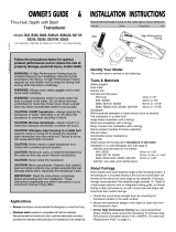
Identify Your Transducer Model
The transducer model number is printed on the cable tag.
triangular
cutting
recess for
anti-rotation bolt
guide
model
number
(some models)

2
Specifications Table 1
Installation
Hole Drilling: Transducer
Cored Fiberglass Hull—Follow separate instructions on page 4.
1. Drill a 3mm or 1/8" pilot hole perpendicular to the waterline from
inside the hull (Figure 1). If there is a rib, strut, or other hull
irregularity near the selected mounting location, drill from the
outside.
2. Using the appropriate size drill bit or hole saw, cut a hole from
outside the hull (Specifications Table 1). Be sure to hold the drill
plumb, so the hole will be perpendicular to the water surface.
Cutting the High-Performance Fairing
CAUTION: The end of the fairing with the arrows/triangular
recess always points forward toward the bow when installed. Be
sure to orient the fairing on the band saw, so the angle cut
matches the intended side of the hull and not the mirror image.
Transducer
Model
Max.
Deadrise
Angle
Min. Fairing
Thickness
Drill Bit/Hole Saw
for
Transducer Hole
Drill Bit for
Anti-rotation Bolt
Hole
B45 26° 35mm (1-3/8") 22mm or 7/8" 11mm or 7/16"
B258 26° 60mm (2-3/8") 30mm or 1-3/16" 14mm or 9/16"
B260 20° 74mm (2-7/8") 33mm or 1-5/16" 14mm or 9/16"
B265LH 20° 74mm (2-7/8") 33mm or 1-5/16" 14mm or 9/16"
B265LM 20° 74mm (2-7/8") 33mm or 1-5/16" 14mm or 9/16"
B275LHW 20° 74mm (2-7/8") 33mm or 1-5/16" 14mm or 9/16"
B285HW 26° 60mm (2-3/8") 30mm or 1-3/16" 14mm or 9/16"
B285M 26° 60mm (2-3/8") 30mm or 1-3/16" 14mm or 9/16"
B744V 24° 32mm (1-1/4") 51mm or 2" 11mm or 7/16"
B744VL 24° 32mm (1-1/4") 51mm or 2" 11mm or 7/16"
B765LH 24° 32mm (1-1/4") 51mm or 2" 11mm or 7/16"
B765LM 24° 32mm (1-1/4") 51mm or 2" 11mm or 7/16"
B785M 24° 32mm (1-1/4") 51mm or 2" 11mm or 7/16"
SS260 20° 74mm (2-7/8") 33mm or 1-5/16" 14mm or 9/16"
SS260
in metal hull
20° 74mm (2-7/8") 35mm or 1-3/8" 15mm or 9/16"
SS505 25° 32mm (1-1/4") 22mm or 7/8" 11mm or 7/16"
SS505
in metal hull
25° 32mm (1-1/4") 25mm or 1" 13mm or 1/2"
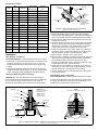
1. Measure the deadrise angle of the hull at the selected mounting
location using an angle finder (Figure 1). Check to be sure the angle
does not exceed the maximum allowed (Specifications Table 1).
2. Tilt the band saw table to the measured angle and secure the
cutting fence (Figure 2).
3. Place the fairing on the table, so the cutting guide rests against
the fence. The end with the triangular recess will be pointing
toward you for installation on the starboard side of the boat or
pointing away from you for installation on the port side.
4. Adjust the cutting fence, so the fairing will be cut in about two
equal parts. There is a minimum thickness for the fairing at its
thinnest dimension (Figure 1 and Specifications Table 1).
5. Recheck steps 1 through 4. Then cut the fairing.
6. When the boat is underway, especially at high speeds, water will
enter any gaps and push against the fairing with considerable
force, possibly rotating it. Shape the fairing to the hull as
precisely as possible with a rasp or power tool. If there is a gap
of more than 3mm (1/8"), replace the fairing.
7. Check to be sure the transducer is flush with the fairing. If it is
recessed more than 0.5mm (1/64") inside the fairing, you may
shim the transducer or carefully file/sand the fairing.
8. Use the remaining section of the fairing with the cutting guide
for the backing block.
Hole Drilling: Anti-rotation Bolt
Cored Fiberglass Hull—Follow separate instructions on page 4.
To locate and drill the hole for the anti-rotation bolt, use the fairing
as a guide. This will ensure that the hole is perpendicular to the
waterline and not drilled at the angle of the hull.
Figure 2. Cutting the High-Performance Fairing
deadrise
angle
cutting
guide
band saw
table
triangular recess
for installation
on starboard side
fence
hull nut
marine
backing block
Figure 1. Bedding and installing a stainless steel transducer and anti-rotation bolt in a metal hull
High-Performance
hull
sealant
stem
aft view
isolation sleeve
min. fairing
thickness
deadrise
angle
slope of hull
parallel to
water surface
Copyright © 2005 - 2016 Airmar Technology Corp.
Copyright © 2005 -2010 Airmar Technology Corp.
transducer
of the hull
end with arrows/
Fairing
isolation
sleeve must
be used in a
metal hull
detail
anti-rotation bolt with isolation sleeve
SS505
(metal)
NOTE: Slide the
isolation sleeves over
the bedding. Put
additional marine
sealant on the
isolation sleeves.
marine
sealant

3
1. Dry fit the transducer in the fairing.
Thread the cable through the large
hole in the fairing and through the
mounting hole in the hull. Seat the
transducer firmly within the recess
in the fairing (Figure 3).
2. Slide the transducer with the
fairing in place into the mounting
hole. Hold the fairing parallel to
the keel, being sure the
triangular recess in the fairing is
pointing forward toward the
bow. Using the bolt hole in the
fairing as your guide, drill a 3mm
(1/8") pilot hole through the hull for
the anti-rotation bolt.
3. Using the appropriate size drill bit or
hole saw and holding the fairing in
place, drill a hole for the anti-rotation
bolt (Specifications Table 1).
4. Remove the assembly and cable
from the mounting hole.
5. Sand and clean the area around
both holes, inside and outside, to
ensure that the sealant will adhere
properly to the hull. If there is any
petroleum residue inside the hull,
remove it with either mild
household detergent or a weak
solvent such as alcohol before sanding.
Metal hull—Remove all burrs with a file and sandpaper.
Bedding the Transducer
CAUTION: Be sure the surfaces to be bedded are clean and dry.
1. Remove the transducer from the fairing.
2. Apply a 2mm (1/16") thick layer of marine sealant to the surface
of the transducer that will contact the fairing and up the stem.
The sealant must extend 6mm (1/4") higher than the combined
thickness of the fairing, hull, backing block, and hull nut
(Figure 3). This will ensure there is marine sealant in the
threads to seal the hull and hold the hull nut securely in place.
Stainless steel transducer/stem in a metal hull—Slide the
isolation sleeve over the bedded transducer stem as far down as
possible (Figure 1). Apply a 2mm (1/16") thick layer of the marine
sealant to the outside of the sleeving.
3. Apply a 2mm (1/16") thick layer of marine sealant to the
following surfaces:
• Fairing that will contact the hull
• Backing block that will contact the hull interior
• Hull nut that will contact the backing block
4. Thread the transducer cable through the fairing and seat the
transducer firmly within the recess.
Installing the Transducer
1. From outside the hull, thread the transducer cable through the
mounting hole. Push the stem of the transducer (with the fairing
in place) into the mounting hole using a twisting motion to
squeeze out excess sealant (Figure 3).
NOTE: The transducer must be FLUSH with the fairing. If it is
recessed more than 0.5mm (1/64") inside the fairing, you may
shim the transducer or carefully file/sand the fairing.
Stainless steel transducer/stem in a metal hull—Be sure the
isolation sleeve is between the transducer stem and the hull
(Figure 1). However, the top of the isolation sleeve must be below
the top of the backing block to prevent the sleeving from
interfering with tightening the hull nut.
2. From inside the hull, slide the backing block onto the transducer
cable and stem, seating the backing block firmly against the
hull. Slide the hull nut along the cable. Screw the hull nut in
place, but do not tighten it at this time.
Bedding & Installing the Anti-rotation Bolt
CAUTION: Be sure the surfaces to be bedded are clean and dry.
1. Apply a 2mm (1/16") thick layer of marine sealant to the anti-
rotation bolt including the flange (Figure 3). The sealant must be
6mm (1/4") higher than the combined thickness of the fairing,
hull, backing block, washer, and nut. This will ensure that there
is marine sealant on the threads to seal the hull and hold the nut
securely in place.
Stainless steel bolt in a metal hull—Slide the isolation sleeve
over the bedded bolt as far down as possible (Figure 1 detail).
Apply a 2mm (1/16") thick layer of the marine sealant to the
outside of the sleeving.
2. Apply a 2mm (1/16") thick layer of marine sealant to the side of
the washer that will contact the backing block.
3. Push the anti-rotation bolt through the fairing and the hull.
4. From inside the hull, screw the washer (sealant side down) and
the nut onto the anti-rotation bolt.
Stainless steel bolt in a metal hull—Be sure the isolation sleeve
is between the bolt and the hull (Figure 1 detail). However, the top
of the isolation sleeve must be below the top of the backing block
to prevent the sleeving from interfering with tightening the hull nut.
5. Use slip-joint pliers to tighten the hull nut. Then tighten the nut on
the anti-rotation bolt. Do not over-tighten, crushing the fairing or
hull.
Cored fiberglass hull—Do not over tighten, crushing the hull.
Wood hull—Allow for the wood to swell before tightening the nuts.
6. Use marine sealant to half fill the hollow in the yellow triangular
plug. Apply a 2mm (1/16") thick layer of marine sealant to the
three sides of the plug that form the triangle. The sealant will
hold the plug firmly within the fairing and fill any gap between
the anti-rotation bolt and the plug.
7. The yellow triangular plug fits one way only. The curved surface
will touch the water. Push the yellow plug into the recess in the
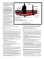
Figure 3. Bedding and installing
Copyright © 2005 - 2016 Airmar Technology Corp.
BOW ►
anti-rotation
bolt
nut &
washer
triangular plug
backing
block
High-
with curved
surface toward
water
hull
hull nut
marine sealant on following (shown in red):
stem
B744V
Performance
Fairing
- transducer, extending above hull nut 1/4" (NOT surface that will touch water)
- backing block that contacts hull
- hull nut that contacts backing block
- anti-rotation washer that contacts backing block
- yellow triangular plug: fill hollow half way (NOT curved surface that will touch water)
- anti-rotation bolt including bolt head, extending above nut 1/4"
- fairing that contacts hull
transducer

35 Meadowbrook Drive, Milford, New Hampshire 03055-4613, USA
•
www.airmar.com
4
Copyright © 2004 - 2018 Airmar Technology Corporation. All rights reserved.
fairing until it is FLUSH with the outside of the fairing. This will
squeeze out excess sealant. If necessary, tap it into place with a
mallet.
NOTE: If the triangular plug is slightly recessed within the fairing,
use sealant to fill the gap. The plug must be FLUSH with the
fairing for good performance.
8. When the boat is underway, especially at high speeds, water will
enter any gaps and push against the fairing with considerable
force, possibly rotating it. Fill any gaps between the fairing and the
hull with marine sealant. If there is any gap greater than 3mm
(1/8"), replace the fairing. Remove the excess sealant on the
outside of the fairing and hull to ensure smooth water flow under
the transducer.
9. Proceed with the installation instructions that came with your
transducer, beginning with “Cable Routing & Connecting.”
Installation in a Cored Fiberglass Hull
The core (wood or foam) must be cut and sealed carefully. The core
must be protected from water seepage, and the hull must be
reinforced to prevent it from crushing under the hull nut, allowing the
transducer to become loose.
Additional Tools & Materials
Drill bits and hole saws (Specifications Table 2)
Cylinder
Wax
Tape
Casting epoxy
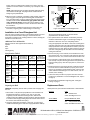
Specifications Table 2
Preparing the Hull
CAUTION: Completely seal the hull to prevent water seepage into
the core.
1. Drill a 3mm or 1/8" pilot hole perpendicular to the waterline from
inside the hull (Figure 4). If there is a rib, strut, or other hull
irregularity near the selected mounting location, drill from the
outside. (If the hole is drilled in the wrong location, drill a second hole
in a better location. Apply masking tape to the outside of the hull over
the incorrect hole and fill it with epoxy.)
2. Using the appropriate size drill bit or hole saw, cut a hole from
outside the hull through the outer skin only (Specifications Table 2).
Model
Drill Bit/Hole
Saw for
Transducer
(outer skin)
Min. Size
Drill Bit/Hole Saw
for Transducer
(inner cored hull)
Drill Bit for
Anti-rotation
Bolt
(outer skin)
Min. Size
Drill Bit for
Anti-rotation Bolt
(inner cored hull)
B45
SS505
22mm
or 7/8"
38mm or 1-1/2" 11mm or 7/16" 25mm or 1"
B258
B285HW
B285M
30mm
or 1-3/16"
50mm or 2" 14mm or 9/16" 30mm or 1-1/4"
B260
B265LH
B265LM
B275LHW
SS260
33mm
or 1-5/16"
50mm or 2" 14mm or 9/16" 30mm or 1-1/4"
B744V
B744VL
B765LH
B765LM
B785M
51mm
or 2"
65mm or 2-5/8" 11mm or 7/16" 25mm or 1"
hull’s outer skin to
hull
outer skin
solid or hollow
cylinder
pour in
casting
epoxy
core
inner skin
Figure 4. Preparing a cored fiberglass hull
Dimension equal to
the thickness of the
ensure adequate
clearance
Be sure to hold the drill plumb, so the hole will be
perpendicular to the water surface.
3. The optimal interior hole diameter is affected by the hull’s
thickness and deadrise angle. It must be large enough in
diameter to allow the core to be completely sealed.
Using the appropriate size drill bit or hole saw cut through the
inner skin and most of the core from inside the hull keeping the
drill perpendicular to the hull (Specifications Table 2). The core
material can be very soft. Apply only light pressure to the hole
saw after cutting through the inner skin to avoid accidentally
cutting the outer skin.
4. Remove the plug of core material, so the inside of the outer
skin and the inner core of the hull is fully exposed. Sand and
clean the inner skin, core, and the outer skin around the hole.
5. Coat a hollow or solid cylinder of the correct diameter with
wax and tape it in place. Fill the gap between the cylinder and
hull with casting epoxy. After the epoxy has set, remove the
cylinder.
6. Sand and clean the area around the hole, inside and outside,
to ensure that the sealant will adhere properly to the hull. If
there is any petroleum residue inside the hull, remove it with
either mild household detergent or a weak solvent, such as
alcohol, before sanding.
7. Follow the same procedure to prepare the hull for the anti-
rotation bolt (“Installation in a Cored Fiberglass Hull”, steps 2
through 6).
8. Proceed with the installation beginning with "Cutting the
Fairing" on page 2.
Replacement Parts
Obtain parts from your instrument manufacturer or marine dealer.
Gemeco
USA
Tel: 803-693-0777
email: [email protected]
Airmar EMEA
Europe, Middle East, Africa
Tel: +33.(0)2.23.52.06.48
email: [email protected]
Copyright © 2005 Airmar Technology Corp.
-
 1
1
-
 2
2
-
 3
3
-
 4
4


Airmar B45, B258, B260, B265LH, B265LM, B275LHW, B285HW, B285M, B744V, B744VL, B765LH, B765LM, B785M, SS260, SS505 High-Performance Fairing Owner's manual
- Type
- Owner's manual
Ask a question and I''ll find the answer in the document
Finding information in a document is now easier with AI
Related papers
-
Airmar B45 Owner's Manual & Installation Instructions
-
-
-
 New Transducers SS505 User manual
-
Raymarine B260 Owner's manual
-
Airmar B122 DST800L Long TRIDUCER Multisensor Owner's manual
-
-
-
Standard Horizon DST528 Owner's manual
-

Other documents
-
Garmin GT30-TH User manual
-
Furuno B265LHG User guide
-
Furuno B175M/12 User guide
-
-
-
Furuno DFF3D User manual
-
Lowrance Structure Scan 3D Thru Hull Installation guide
-
-
-