Page is loading ...

NETWORK FISH FINDER
DFF1-UHD
OPERATOR'S MANUAL
www.furuno.com
Model


i
IMPORTANT NOTICES
General
• This manual has been authored with simplified grammar, to meet the needs of international users.
• The operator of this equipment must read and follow the instructions in this manual.
Wrong operation or maintenance can void the warranty or cause injury.
• Do not copy any part of this manual without written permission from FURUNO.
• If this manual is lost or worn, contact your dealer about replacement.
• The contents of this manual and the equipment specifications can change without notice.
• The example screens (or illustrations) shown in this manual can be different from the screens you
see on your display. The screens you see depend on your system configuration and equipment
settings.
• Save this manual for future reference.
• Any modification of the equipment (including software) by persons not authorized by FURUNO will
void the warranty.
• The following concern acts as our importer in Europe, as defined in DECISION No 768/2008/EC.
- Name: FURUNO EUROPE B.V.
- Address: Ridderhaven 19B, 2984 BT Ridderkerk, The Netherlands
• All brand, product names, trademarks, registered trademarks, and service marks belong to their
respective holders.
How to discard this product
Discard this product according to local regulations for the disposal of industrial waste. For disposal in
the USA, see the homepage of the Electronics Industries Alliance (http://www.eiae.org/) for the
correct method of disposal.
How to discard a used battery
Some FURUNO products have a battery(ies). To see if your product has a battery, see the chapter
on Maintenance. If a battery is used, tape the + and - terminals of the battery before disposal to pre-
vent fire, heat generation caused by short circuit.
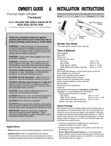
In the European Union
The crossed-out trash can symbol indicates that all types of batteries
must not be discarded in standard trash, or at a trash site. Take the
used batteries to a battery collection site according to your national
legislation and the Batteries Directive 2006/66/EU.
In the USA
The Mobius loop symbol (three chasing arrows) indicates that
Ni-Cd and lead-acid rechargeable batteries must be recycled.
Take the used batteries to a battery collection site according to
local laws.
In the other countries
There are no international standards for the battery recycle symbol. The number of symbols can in-
crease when the other countries make their own recycle symbols in the future.
Cd
Ni-Cd Pb

ii
SAFETY INSTRUCTIONS
Do not operate the equipment with
wet hands.
Electrical shock can result.
Do not place liquid-filled containers
on the top of the equipment.
Electrical shock can result.
Use the proper fuse.
Use of a wrong fuse can damage the
equipment and may cause fire.
WARNING
Indicates a potentially hazardous situation which, if not avoided,
could result in death or serious injury.
CAUTION
Indicates a potentially hazardous situation which, if not avoided,
may result in minor or moderate injury.
Warning, Caution
Mandatory Action
Prohibitive Action
The user and installer must read the appropriate safety instructions before attempting to install
or operate the equipment.
WARNING
WARNING
Do not open the equipment.
Only qualified personnel can work inside
the equipment.
Do not disassemble or modify the
equipment.
Fire, electrical shock or serious injury can
result.
Turn off the power immediately if the
equipment is emitting smoke or fire.
Fire or electrical shock can result if the
power is left on.
Turn off the power immediately if water
leaks into the equipment or an object is
dropped inside the equipment.
Continued use can cause fire or electrical
shock.
Turn off the power immediately if you
feel the equipment is acting abnormally.
If the equipment is hot to the touch or is
emitting strange noises, turn off the power
immediately and contact your dealer for
advice.
WARNING
Safety instructions for the operator
Name: Warning Label (1)
Type: 86-003-1011-3
Code No.: 100-236-233-10
A warning label is attached to the equipment.
Do not remove the label. If the label is missing
or illegible, contact a FURUNO agent or dealer
about replacement.

SAFETY INSTRUCTIONS
iii
Standard
compass
Steering
compass
0.70 m 0.40 m
CAUTION
CAUTION
The transducer cable must be handled
carefully, following the guidelines
below.
• Keep fuels and oils away from the
cable.
• Locate the cable away from chemicals.
• Locate the cable away from locations
where it might be damaged.
Do not apply the power with the
transducer exposed to air.
The transducer may be damaged.
A magnetic compass may receive inter-
ference if it is placed too close to the
network fish finder. Observe the com-
pass safe distances shown below to
prevent interference to a magnetic
compass.
WARNING
WARNING
Do not work inside the equipment
unless qualified to do so.
Electricla shock can occur.
Turn off the power before beginning
the installation.
Fire or electrical shock can result if the
power is left on.
Be sure no water leaks at the mounting
location for the transducer and temp-
erature sensor.
Water leakage can sink the vessel. Also,
confirm that neither the transducer nor
the sensor will loosen by vibration. The
installer is solely responsible for the
installation.
Confirm that the power supply voltage
is within the rating of this equipment.
Incorrect voltage will damage the equip-
ment and may cause fire.
The network sounder meets
waterproofing standard IP55. However,
do not install the sounder outdoors.
Fire or electrical shock can result if water
gets inside the equipment.
Safety instructions for the installer

iv
TABLE OF CONTENTS
FOREWORD .................................................................................................................. v
SYSTEM CONFIGURATION ....................................................................................... vL
1. INSTALLATION ...................................................................................................... 1
1.1 Equipment Lists........................................................................................................... 1
1.2 Network Fish Finder .................................................................................................... 2
1.3 Transducer ..................................................................................................................3
1.4 Optional Speed/Temperature Sensors ST-02MSB, ST-02PSB .................................. 3
1.4.1 Mounting considerations...................................................................................... 3
1.4.2 Mounting procedure............................................................................................. 3
2. WIRING ................................................................................................................... 4
2.1 Wiring Outline..............................................................................................................4
2.2 Transducer Cable, Cable for External KP (option)...................................................... 5
2.2.1 How to prepare the cables................................................................................... 5
2.2.2 How to connect the transducer cable .................................................................. 7
2.2.3 How to connect the cable for the external KP...................................................... 9
2.3 LAN Cable................................................................................................................. 11
3. INITIAL SETTINGS ............................................................................................... 13
3.1 DIP Switch Setting .................................................................................................... 13
3.2 Operation Check ....................................................................................................... 14
4. MAINTENANCE .................................................................................................... 15
4.1 Maintenance.............................................................................................................. 15
4.2 How to Replace the Fuse.......................................................................................... 16
4.3 How to Restore Default Settings ............................................................................... 16
APPENDIX 1 JIS CABLE GUIDE ............................................................................ AP-1
APPENDIX 2 INSTALLATION OF TRANSDUCERS ..............................................AP-2
APPENDIX 3 INSTALLATION OF TEMPERATURE SENSORS............................AP-7
SPECIFICATIONS ................................................................................................... SP-1
PACKING LIST .......................................................................................................... A-1
OUTLINE DRAWING ................................................................................................. D-1
INTERCONNECTION DIAGRAM .............................................................................. S-1

v
FOREWORD
A Word to the Owner of the DFF1-UHD
Congratulations on your choice of the FURUNO DFF1-UHD Network Fish Finder. We are confident
you will see why the FURUNO name has become synonymous with quality and reliability.
Since 1948, FURUNO Electric Company has enjoyed an enviable reputation for quality marine elec-
tronics equipment. This dedication to excellence is furthered by our extensive global network of
agents and dealers.This equipment is designed and constructed to meet the rigorous demands of the
marine environment. However, no machine can perform its intended function unless operated and
maintained properly. Please carefully read and follow the recommended procedures for operation
and maintenance.
Thank you for considering and purchasing FURUNO.
Features
The DFF1-UHD is a dual frequency echo sounder designed for use with the NavNet 3D (MFD8/12/
BB), NavNet TZtouch (TZT9/14/BB) and NavNet TZtouch2 (TZTL12F/15F, TZT2BB). The DFF1-
UHD feeds data about underwater conditions via a LAN connection.
• FURUNO TruEcho CHIRP
TM
fish finders provide very high definition images.
• High resolution display greatly reduces the possibility of missing a target.
• Noise-suppressing display for enhanced detection performance.
• Fish size shown for depths up to 200 m and bottom discrimination.
Operational cautions
• Echoes are shown in high ultra definition, thus echoes are displayed differently from those present-
ed on the conventional fish finder.
• The interference rejector operates differently from the interference rejector on the conventional fish
finder, thus its effect on echoes is different.
• The transducer cannot be installed inside the vessel.
• Observe the following when using the ACCU-FISH
TM
feature:
• Use the feature where the depth is 2 - 200 m.
• The length of the TX pulse changes according to whether the feature is on or off.
The appearance of the display changes with the sensitivity.
• Observe the following when using the bottom discrimination display (hereafter referred to as BDD):
• Use the BDD under the following conditions:
- Depth: 5-200 m (16.4-656.2 ft)
- Speed: 10 knots or less”
• The BDD uses depth measured from the vessel’s draft in its analysis of bottom composition.
Be sure to set the draft at the NavNet 3D/TZtouch/TZtouch2.
• The TX interval slows when the BDD is active.
• The BDD is inoperative if the transducer selection setting at the NavNet 3D/TZtouch/TZtouch2
is ”Manual”.
• The BDD provides an estimate of bottom composition. Actual composition may be different.
Measure for reduction of interference
If you receive interference from the fish finder/echo sounder of another vessel, switch to single fre-
quency operation and change the frequency and/or reduce the transmitting sound pressure level to
remove the interference.
CE declaration
With regards to CE declarations, please refer to our website (www.furuno.com) for further information
about RoHS conformity declarations.

vi
SYSTEM CONFIGURATION
100/110/
220/230 VAC
1ø, 50/60 Hz
NETWORK FISH FINDER
DFF1-UHD
12-24 VDC
Transducer
Rectifier
PR-62
Speed/Temperature Sensor
ST-02MSB
ST-02PSB
Temperature Sensor
T-04MSB
T-04MTB
NavNet Equipment
MFD8/12/BB
TZT9/14/BB
TZTL12F/15F, TZT2BB
B265LH
B275LH-W
CM265LH
CM275LH-W
Ethernet HUB
HUB-101
External
KP

1
1. INSTALLATION
1.1 Equipment Lists
Standard supply
Optional supply
* : Not compatible with Bottom Discrimination Display and ACCU-FISH
™
features.
Name Type Code No. Qty Remarks
Network Fish Finder DFF1-UHD - 1
Spare Parts SP02-05601 001-033-740 1 set Fuse (2 pcs.)
Installation Materials CP02-08500 000-011-917 1 set - Power cable assy. (3.5 m)
- LAN cable assy. (5 m)
- Self-tapping screws
Name Type Code No. Remarks
Transducer B265LH 000-022-521 1 kW, bronze housing, thru hull
B275LH-W* 000-027-419 1 kW, bronze housing, thru hull, wide beam
CM265LH 000-022-531 1 kW, plastic housing, tank mount
CM275LH-W* 000-027-408 1 kW, plastic housing, tank mount, wide beam
Thru-hull pipe TFB-7000 000-022-532
Tank T-711 000-022-539
Cable Assembly MOD-Z072-020+ 001-167-880-10 2 m, for HUB-101
Cable Assembly MOD-Z072-100+ 001-167-900-10 10 m, for HUB-101
Speed/Tem-
perature Sensor
ST-02MSB 001-164-150-10 Thru-hull mount, steel hull
ST-02PSB 001-164-160-10 Thru-hull mount, plastic hull
Temperature
Sensor
T-04MSB 000-026-893 Thru-hull mount
T-04MTB 000-026-894 Transom mount
Rectifier PR-62 000-013-484 100 VAC
000-013-485 110 VAC
000-013-486 220 VAC
000-013-487 230 VAC
Connector Kit for
TX Sync
OP02-86 001-205-780

1. INSTALLATION
2
1.2 Network Fish Finder
The network fish finder can be installed on a desktop, deck or on a bulkhead. When selecting a
mounting location, keep the following points in mind:
• This unit meets the waterproofing standard IP55. However, do not install the unit outdoors.
• The operating temperature range of this unit is -15°C to 55°C (5°F to 131°F). Be sure the mount-
ing location satisfies this requirement.
• Locate the unit away from exhaust pipes and vents.
• The mounting location should be well ventilated.
• Mount the unit where shock and vibration are minimal.
• Keep the unit away from electromagnetic field-generating equipment such as motors and gen-
erators.
• Leave slack in cables for maintenance and servicing ease.
• A magnetic compass may receive interference from the network fish finder if it is placed too
close to the network fish finder. Observe the compass safe distances noted in the safety instruc-
tions to prevent interference to the magnetic compass.
• For mounting on a bulkhead, the connectors must face downward.
Fasten the network fish finder to the mounting location with four self-tapping screws (5×20), refer-
ring to the outline drawing at the back of this manual for mounting dimensions.

1. INSTALLATION
3
1.3 Transducer
The performance of the fish finder largely depends upon the transducer position. Select a place
least affected by air bubbles since turbulence blocks the sounding path. The face of the transducer
must be facing the sea bottom in normal cruising trim of the boat. Further, select a place least in-
fluenced by engine noise. It is known that air bubbles are fewest at the place where the bow first
falls and the next wave rises, at usual cruising speed.
Do not install the transducer inside the hull. Performance cannot be guaranteed.
1.4 Optional Speed/Temperature Sensors
ST-02MSB, ST-02PSB
1.4.1 Mounting considerations
• Select a mid-boat flat position. The sensor does not have to be installed perfectly perpendicular.
However, the sensor must not be located where it may be damaged in dry-docking operations.
• Select a place apart from equipment generating heat.
• Select a place in the forward direction viewing from the drain hole, to allow for circulation of cool-
ing water.
• Select a place free from vibration.
• Do not install near the transducer of an echo sounder, to prevent interference to the echo
sounder.
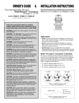
1.4.2 Mounting procedure
1. Dry dock the boat.
2. Make a hole of approx. 51 mm in diameter
in the mounting location.
3. Unfasten the locknut and remove the
sensor section.
4. Apply high-grade sealant to the flange of
the sensor.
5. Pass the sensor casing through the hole.
6. Face the notch on the sensor toward boat's
bow and tighten the flange.
7. Set the sensor section to the sensor casing
and tighten the locknut.
8. Launch the boat and check for water leak-
age around the sensor.
Locknut
123
Face "notch"
toward bow.
Flange nut
Coat with
marine sealant.
51
Brim
ø77

4
2. WIRING
2.1 Wiring Outline
Connect the power cable, transducer cables, sensor cable, network cable and ground wire to their
respective locations on the network fish finder. See the next page for how to connect the trans-
ducer cable.
Ground
Connect a ground wire (IV-2 sq, local supply) between the
ground terminal and ship’s ground to prevent interference to
the sounder picture. Make the length of the wire as short as
possible. For FRP vessels, install a ground plate that mea-
sures approx. 20 cm by 30 cm on the outside of the hull bot-
tom and connect the ground wire there.
White
Black
Ground wire
(IV-2 sq)
DFF1-UHD
MOD-Z072-050+, 5 m
(option: 2/10 m)
NavNet equipment
GROUND
MJ-A3SPF0013-035C
(3.5 m)
External
KP
Temperature or
Speed/Temperature
Sensor*
Transducer
BATTERY
12 - 24 VDC
Shield (green)
* For no connection,
cover connector
with supplied cap.
To HUB-101
CAUTION
Ground the equipment
to prevent mutual
interference.

2. WIRING
5
2.2 Transducer Cable, Cable for External KP (option)
If the external KP is not to be connected, do only the applicable procedures in section 2.2.1 and
2.2.2.
The KP from an echo sounder or sonar can be connected to this network fish finder to synchronize
transmission between the sounder and this network fish finder. Use the optional Connector Kit for
TX Sync (Type, OP02-86, Code No. 001-205-780) and cable MPYC-4 (or MPYC-2) for the con-
nection. (The MPYC-4 is a Japan Industrial Standard (JIS) cable. If not available locally, see the
Appendix 1 for how to select the equivalent cable.)
Connector kit for TX sync
2.2.1 How to prepare the cables
Note: The label on the transducer cable can be removed if it interferes with treatment of the cable.
How to prepare the transducer cable
CM265LH/CM275LH-W
B265LH/B275LH-W
Name Type Code No. Qty Remarks
Upset UI Screw-B M4u20 000-163-756-10 2
Super Gland MGB20M-12B 000-177-248-10 1
PH Connector Assembly 02-1097 (4P) 001-206-000 1
Cable Clamping Plate 02-167-1528 100-379-090-10 1
Rainproof Panel 02-167-1529 100-379-100 1 No use. May be
discarded.
EMI Core GRFC-10 000-177-010-10 1
Crimp-on Lug NCW-1.25 000-157-213-10 4
Braided shield
Taping
Sheath
Extract braided shield and wrap it around sheath.
(This part lies in cable clamp.)
Extract cores from here and cut inclusion.
6
20
Approx. 100
Approx. 100
Vinyl tape (one turn)
㪍
20
Wind shield around cable.
(This part lies in cable clamp.)
Extract cores from here and
cut inner materials.
Put unused wires (3)
in vinyl tubing (local
supply) for insulation.

2. WIRING
6
How to prepare the cable for the external KP
1. Prepare the PH connector (02-1097, optional supply) as shown below.
a) Make the length of the wires of the PH connector 100 mm.
b) Remove the sheath from the cores 10 mm.
c) Fold back the cores in half.
d) Attach crimp-on lug NCW-1.25 to each core.
2. Remove the armor 210 mm and cut off the vinyl sheath 90 mm.
3. Remove 5 mm of the vinyl sheath from the cores then connect each crimp-on lug (attached at
step 2) as shown below.
4. Wrap the armor with vinyl tape.
(b)
Approx. 10 mm
(a)
Approx. 100 mm
(c) (d)
Fold back core.
A
rmor
MPYC-4
Approx. 210 mm
Vinyl sheath
Approx. 90 mm
Approx. 5 mm
This part is fixed
with the lock nut
inside the unit.
This part is fixed
with the cable
clamp.
Armor
Tape here.
Vinyl sheath
Crimp-on lug
NCW-1.25

2. WIRING
7
2.2.2 How to connect the transducer cable
This procedure shows you how to connect the transducer cable.
1. Open the cover - grasp the cover at two sides, spread the cover slightly and lift.
2. Loosen four screws to remove the shield cover.
3. Detach the two WAGO connectors (TB3, TB4) inside the equipment.
4. Unfasten the sealing nut from the super gland for the transducer cable.
WAGO connector
opener
WAGO connectors
TB4
TB3
Sealing nut
Super gland

2. WIRING
8
5. Loosen two screws to unfasten the clamp fixing plate for the transducer cable.
6. Pass the transducer cable through the sealing nut and super gland and into the unit.
7. Use the WAGO connector opener, attached inside the equipment (see the figure on page 7
for the location), to connect the transducer cable to the WAGO connectors, following the in-
structions in the figure below and the interconnection diagram.
8. Reattach the WAGO connectors to the circuit board.
9. Fasten the clamp fixing plate, referring to the table below for how to orient the plate.
Transducer model Clamp fixing plate orientation
CM265LH/
CM275LH-W
Projection on plate upward
B265LH/
B275LH-W
Projection on plate downward
Loosen two screws to unfasten cable
clamping plate for transducer cable.
1. Twist conductors.
2. Insert opener as directed and press it down.
3. Insert core to hole.
4. Release opener.
5. Pull the core to make sure it is correctly inserted.
WAGO connector opener
Core
Twist.
Push

2. WIRING
9
10. Tighten the sealing nut according to the information in the table below.
11. Reattach the shield cover and close the outer cover.
2.2.3 How to connect the cable for the external KP
1. Remove the cover, shield cover. (See step 1 in section 2.2.2 for how to open the cover.)
2. Detach the protective sheet from the location for the external KP.
3. Do the following:
1) Unfasten the sealing nut and lock nut from the supplied super gland. As shown below,
pass the cable through the sealing nut, super gland, hole in the network fish finder and the
lock nut.
2) Prepare the cable end, referring to "How to prepare the cable for the external
KP" on page 6.
Transducer
Clearance between super gland and
sealing nut
Torque
CM265LH/
CM275LH-W
4 mm 1.8 - 2.0 Nm
B265LH/
B275LH-W
2 mm
Clearance
Protective sheet
Lock nut
Super gland
Sealing nut
Cable for
external KP
(MPYC-4)

2. WIRING
10
4. Tighten the lock nut.
5. Tighten the sealing nut until the clearance between the nut and
super gland is 4 mm. The torque for the sealing nut is 1.8 - 2.0
Nm.
6. Position the cable so the vinyl sheath lies in the cable clamp
then use the supplied clamp fixing plate and two upset screws to secure the cable.
7. Pass the cable through the edge saddle shown below then connect the cable to J12 on the
PWRTX board. Be sure the cable does not contact TB4.
Note: For cable MPYC-2, tape the vinyl sheath of the cable (approx. 6 to 7 turns) where it lies
in the cable clamp and fasten the cable clamp. The PH connector has two unused harnesses.
Cut them at their base or wrap them with vinyl tape.
4 mm
Clamp fixing plate
for external KP
Edge saddle
J12
Be sure cable does
not contact TB4.
Taping.
Cut off two unused
harnesses at base.

2. WIRING
11
8. Attach the supplied EMI core (GRFC-10) to the cable for the external KP, approx. 10 mm from
the super gland.
9. Attach the shield cover and close the cover.
2.3 LAN Cable
Do as follows to connect the supplied LAN cable (MOD-Z072-050+) or the optional LAN cable
(MOD-Z072-020+, MOD-Z072-100+).
1. Unfasten the sealing nut from the LAN connector then remove the sealing insert and clamping
claw.
2. Detach the sealing insert from the clamping claw as shown below.
EMI coreEMI core
10 mm10 mm
Super glandSuper gland
How to detach clamping claw
Hold the clamping
claw/seal assy. as shown
left, with the teeth of
the clamping claw toward
you.
Push in the sealing insert
with your thumbs.
Sealing nut
Seal assy.Seal assy.
Clamping
claw
Sealing
insert
Super
gland

2. WIRING
12
3. Pass the sealing nut, clamping claw and sealing insert onto the LAN cable in the order shown
in the figure below. Connect the cable to the LAN connector. (Note the orientation of the seal-
ing insert when passing it onto the cable. Push the cable into the slit in the sealing insert.)
4. Set the sealing insert and clamping claw into the sealing nut then tighten the nut.
5. Tighten the sealing nut to fasten the LAN cable. The clearance between the sealing nut and
the super gland shall be 3 mm. The torque for the sealing nut is 1.8 - 2.0 Nm.
How to disconnect the LAN cable
Loosen the two screws on the gland to access the cable’s connector. A lock washer is fitted to the
gland, so the screws cannot be unfastened completely.
Sealing nut
LAN cable
Sealing insert
(Push cable into slit.)
Clamping claw
Clearance
Screw (2 pcs.)
Gland
/