Page is loading ...

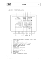
Cordex 48-1kW
23" Shelf For Systems Up To
4000W With Distribution
030-704-B2

Argus Technologies Ltd. Visit www.argus.ca
Burnaby, British Columbia. Telephone: 604 436 5900 Fax: 604 436 1233
Argus Technologies reserves the right to make changes to the products and information contained in this document without notice.
Copyright 2008 Argus Technologies Ltd. Argus
®
is a registered trademark of Argus Technologies Ltd. All Rights Reserved.
Printed in Canada.
This page intentionally left blank.

Argus Technologies Ltd. 030-704-B2 Rev B WC
Printed in Canada. © 2004 Argus Technologies Ltd. ARGUS and CORDEX are trademarks of Argus Technologies Ltd. All Rights Reserved.
Cordex 48-1kW
23” Shelf For Systems
Up To 4000W With Distribution
030-704-B2
The following documents and drawings are included in this manual to provide the necessary information required for
installation, operation and fault diagnosis of the unit:
• Installation and Operation Instructions: 030-704-C0
• Operation Instructions, Cordex 1kW Rectifier: 010-566-C0
• Specifications, Cordex 1kW Rectifier: 010-566-B1
• CSA/NRTL Equivalence: 048-554-10
• Outline Drawing, 23” Shelf: 030-704-06
• Customer Connections: 030-704-08
• Warranty Policy: 048-507-10
• Factory Service Information: 048-527-10

MANUAL ADDENDUM
MANUAL ADDENDUM
Unit Description: CORDEX CONTROLLER
Item Changed: Null modem cable (for front Craft Port use)
# Date Page# Correction to be implemented
1 06-01-26 3
of 018-557-B1
3
of 018-557-B5
3
of 018-570-B1
Change part number 877-162-20 to 877-482-20.
2 10
of 010-567-C0
10
of 010-572-C0
12
of 018-557-C0
12
of 018-557-C3
11
of 018-570-C0
8
of 030-704-C0
9
of 030-706-C0
8
of 030-713-C0
50
of 034-057-C0
65
of 034-057-C3
54
of 034-069-C0
75
of 034-069-C3
Change figure to:
Authorized by: FORM: 954-010-10 Rev B 87716220a1_addendum_nullmodem.doc

IMPORTANT SAFETY INSTRUCTIONS
SAVE THESE INSTRUCTIONS
This manual contains important safety and installation instructions
for Argus’ Modular Switched Mode Rectifier System Cordex™ 48-1kW.
1. Please read this manual prior to use to become familiar with the system’s numerous features and
operating procedures. To obtain a maximum degree of safety, follow the sequences as outlined.
2. This manual provides warnings and special notes for the user:
a. Points that are vital to the proper operation of the system or the safety of the operator
are indicated by the heading: WARNING.
b. A notation that is in Bold Italic typeface covers points that are important to the
performance or ease of use of the system.
3. Before using the system, read all instructions and cautionary markings on the system and any
equipment connected to the system.
4. Do not expose the system to rain or snow.
5. CAUTION – Unless otherwise noted, use of an attachment not recommended or sold by the system
manufacturer may result in a risk of fire, electric shock, or injury to persons.
6. CAUTION – Do not operate the system if it has received a sharp blow, it has been dropped, or
otherwise damaged in any way – return it to a qualified service center for repair.
7. CAUTION – Do not disassemble the system – call our qualified service centers for servicing.
Incorrect reassembling may result in a risk of electrical shock or fire.
i

ARGUS TECHNOLOGIES CORDEX 48-1KW 23" SHELF FOR SYSTEMS UP TO 4000W WITH DISTRIBUTION
TABLE OF CONTENTS
1 INTRODUCTION.............................................................................................................................1
1.1 Scope of the Manual.........................................................................................................................1
1.2 Product Overview.............................................................................................................................1
1.3 Part Numbers and List Options........................................................................................................2
2 INSPECTION .................................................................................................................................3
2.1 Packing Materials.............................................................................................................................3
2.2 Check for Damage............................................................................................................................3
3 INSTALLATION..............................................................................................................................4
3.1 Safety Precautions............................................................................................................................4
3.2 Shelf Preparation/Mounting .............................................................................................................4
3.3 Module Insertion/Removal...............................................................................................................4
4 WIRING AND CONNECTIONS..........................................................................................................5
4.1 Safety Precautions............................................................................................................................5
4.2 Tools Required.................................................................................................................................5
4.3 Power System Chassis Ground.........................................................................................................5
4.4 AC Feeder Protection/Sizing............................................................................................................5
4.5 AC Input Connections......................................................................................................................6
4.6 Calculating Output Wire Size Requirements ...................................................................................6
4.7 DC Output Connections ...................................................................................................................6
4.8 CAN Serial Port................................................................................................................................7
4.9 Ethernet Side Access (List Option 93).............................................................................................7
4.10 Network Connection and Remote Communications via CXCM......................................................7
4.11 CXCM Battery –48V Connection....................................................................................................8
4.12 Alarm and Signal Wiring Connections for CXCM..........................................................................8
4.13 Analog Inputs for CXCM.................................................................................................................9
4.14 Digital Inputs for CXCM ...............................................................................................................10
4.15 Alarm (Relay) Outputs for CXCM.................................................................................................11
5 SYSTEM STARTUP......................................................................................................................12
5.1 CXCM Reset ..................................................................................................................................12
6 MAINTENANCE ...........................................................................................................................13
7 ARGUS CONVENTIONS................................................................................................................14
7.1 Numbering System.........................................................................................................................14
7.2 Acronyms and Definitions..............................................................................................................14
ii

ARGUS TECHNOLOGIES CORDEX 48-1KW 23" SHELF FOR SYSTEMS UP TO 4000W WITH DISTRIBUTION
1 INTRODUCTION
1.1 Scope of the Manual
This instruction manual explains the installation and interconnection of Argus Technologies’ Cordex 48-1kW 23”
Integrated Shelf System with up to 4000W Output Power and Distribution.
To aid the user with installation, frequent reference is made to drawings located at the rear of this manual.
NOTE: Separate documentation will be provided detailing the software features,
setup and operation of the Cordex CXCM System Controller.
1.2 Product Overview
A complete Cordex rectifier system consists of a CXCM with one or more power modules in a common shelf
enclosure. The shelf can be mid-mounted in a 23” rack and has connections for AC inputs, DC output, and system
communications.
Cordex rectifier modules use a high frequency, switched mode conversion technique to provide a fully regulated
and isolated DC output from the AC mains. The rectifier input is wide range to allow use on 208/220/240 50/60
Hz electrical services. Rectifier power modules are “hot swappable” meaning they can be inserted or removed
from the shelf without cutting power to or from the system or the load. Additional power modules can be included
with the system at the time of ordering or added after the shelf has been installed. See documents #010-566-B1
and #010-566-C0 in this documentation package.
The integrated shelf rectifier system is designed to operate with the Argus Cordex CXCM (modular version of the
CXC controller); which plugs directly into the rectifier system shelf. See Figure 1 below. Details for installation
and wiring are provided in the respective chapters of this documentation package.
The CXCM allows the user to set up, control and monitor the entire power system and ancillary components from
one central, easy-to-use source. Details of controller operation are provided in the current version software
manual.
The distribution component features up to six AM-style bullet-type breakers with a capacity of 100A. A low
voltage disconnect (LVD) is optional and has a capacity of 125A. Also available is a separate battery breaker with
a capacity of 100A.
A fuse distribution option is available to provide up to ten GMT fuse positions in two feeds rated at 10A
maximum per feed.
Figure 1–Cordex 4000W system with plug-in controller and distribution
030-704-C0
REV A PAGE 1 OF 14

ARGUS TECHNOLOGIES CORDEX 48-1KW 23" SHELF FOR SYSTEMS UP TO 4000W WITH DISTRIBUTION
1.3 Part Numbers and List Options
The shelf is available to order under the following part numbers and list options:
Description Part Number/List Option
Cordex 48-1kW 23" Shelf for Systems up to 4000W with Distribution...................................................030-704-20
[equipped to receive one CXCM controller and four CXRC 48-1kW rectifiers (Figure 1)]....................... *List 0
208/220/240Vac input (dual feeds) .................................................................................................................. *List 6
Gray finish...................................................................................................................................................... *List 50
Temperature sensor, 1/4” lug, 12 ft.................................................................................................................. List 72
Temperature sensor, 3/8” lug, 12 ft.................................................................................................................. List 75
Circuit breaker distribution, AM-style, bullet-type, six load positions........................................................ **List 80
Circuit breaker distribution, AM-style, bullet-type, two load positions, four battery positions................... **List 82
Circuit breaker distribution, AM-style, bullet-type, four load positions, two battery positions................... **List 84
DC output adapters, dual 2-position, 5/8” centers............................................................................................ List 85
Load LVD......................................................................................................................................................... List 86
Battery LVD..................................................................................................................................................... List 87
Fuse distribution, ten-position GMT................................................................................................................ List 88
Power module blank plate (includes List 50)................................................................................................... List 90
Side access (RJ-45) communications jack........................................................................................................ List 93
Breaker, mid-trip, 5A ..................................................................................................................................... List 100
Breaker, mid-trip, 10A ................................................................................................................................... List 101
Breaker, mid-trip, 20A ................................................................................................................................... List 102
Breaker, mid-trip, 30A ................................................................................................................................... List 103
Breaker, mid-trip, 40A ................................................................................................................................... List 104
Breaker, mid-trip, 50A ................................................................................................................................... List 105
Breaker, mid-trip, 60A ................................................................................................................................... List 106
Breaker, mid-trip, 70A ................................................................................................................................... List 107
Breaker, mid-trip, 80A ................................................................................................................................... List 108
Breaker, mid-trip, 90A ................................................................................................................................... List 109
Breaker, mid-trip, 100A ................................................................................................................................. List 110
Breaker, series-trip, 60A........................................................................................................................... ***List 156
Breaker, series-trip, 100A......................................................................................................................... ***List 160
* Default option ** Must order one of List 80, 82, or 84 *** Recommended for battery breaker
The above information is valid at the time of publication. Consult factory for up-to-date ordering information.
P
AGE 2 OF 14 030-704-C0 REV A

ARGUS TECHNOLOGIES CORDEX 48-1KW 23" SHELF FOR SYSTEMS UP TO 4000W WITH DISTRIBUTION
2 INSPECTION
2.1 Packing Materials
All Argus products are shipped in rugged, double walled boxes and suspended via solid inserts to minimize shock
that may occur during transportation. Packaging assemblies and methods are tested to National Safe Transit
Association standards.
Products are also packaged with Cortex. This plastic wrap contains a corrosive-inhibitor that protects the system
from corrosion for up to two years.
2.1.1 Returns for Service
Save the original shipping container. If the unit needs to be returned for service, it should be packaged in its
original shipping container. If the original container is unavailable, make sure the unit is packed with at least three
inches of shock-absorbing material to prevent shipping damage. Argus Technologies is not responsible for
damage caused by the improper packaging of returned units.
2.2 Check for Damage
Prior to unpacking the equipment, note any damage to the shipping container. Unpack the equipment and inspect
the exterior for damage. If any damage is observed contact the carrier immediately.
Continue the inspection for any internal damage. In the unlikely event of internal damage, please inform the
carrier and contact Argus Technologies for advice on the impact of any damage.
Verify that you have all the necessary parts per your order for the proper
assembly of your system.
030-704-C0
REV A PAGE 3 OF 14

ARGUS TECHNOLOGIES CORDEX 48-1KW 23" SHELF FOR SYSTEMS UP TO 4000W WITH DISTRIBUTION
3 INSTALLATION
This chapter is provided for qualified personnel to install the shelf.
To aid the user with installation, frequent reference is made to drawings located at the rear of this manual.
3.1 Safety Precautions
WARNING
Hazardous voltages are present at the input of power systems. The DC output
from the rectifiers and the battery system though not dangerous in voltage has a
high short circuit current capacity that may cause severe burns and electrical
arcing.
Before working with any live battery or power system/distribution center, the following precautions should be
followed:
• Remove all metallic jewelry; e.g., watches, rings, eyeglasses, necklaces.
• Wear safety glasses with side shields at all times during installation.
Insulated metallic tools shall be used.
The installer should follow all applicable local rules and regulations for electrical and battery installations; e.g.,
CSA, UL, CEC, NEC, OSHA, and local fire codes.
3.2 Shelf Preparation/Mounting
The shelf has been designed for mounting in a standard 23” relay rack. Mounting brackets accommodate either 1”
or 1-3/4” rack spacing. The shelf should be mounted to the rack using at least two #12 – 24 x 1/2” screws in each
bracket. Philips-type screws and screwdriver should be used to eliminate the possibility of slippage and scratching
of the unit's exterior. Washers (such as internal tooth) or special screws that are designed to cut through the
painted surface should be used to ensure a good chassis ground.
The shelf shall be mounted in a clean and dry environment. Allow at least 1.75” of free space around the unit
for unrestricted convection cooling airflow.
3.3 Module Insertion/Removal
Insert by placing the module on the shelf bottom and sliding the module into the rear connectors (inside of the
shelf). Apply pressure on the handles to engage the rear connector in the shelf receptacle. Tighten the screw on
the bottom of the faceplate to secure the module to the shelf.
WARNING
Do not force a module into position if it does not seat properly. All modules are
keyed to ensure that the correct module type is used.
To remove modules, loosen the screw on the bottom of the faceplate. Grasp handle and pull out, sliding the
module away from the rear connectors and out of the shelf.
Consult the drawings located at the rear of this manual and proceed to the next section for wiring connections.
P
AGE 4 OF 14 030-704-C0 REV A

ARGUS TECHNOLOGIES CORDEX 48-1KW 23" SHELF FOR SYSTEMS UP TO 4000W WITH DISTRIBUTION
4 WIRING AND CONNECTIONS
This chapter provides cabling details and notes on cable sizing for DC applications with respect to the shelf.
Refer also to drawings at the rear of this manual.
4.1 Safety Precautions
WARNING
Hazardous AC voltages may be present. Ensure power at the AC service panel is
off before attempting work on the AC connections. Use a voltmeter to verify the
absence of voltage. Clearly mark the correct polarity of the battery leads before
commencing work on DC connections.
Refer to the previous (Installation) chapter for additional safety precautions.
4.2 Tools Required
Various tools are essential for product installation. Use this list as a guide:
• Slot head screwdrivers (blade sizes: 1/4”, 1/8”, 1/16”)
• Philips head screwdriver, #2 (tip size 3/16”)
• Digital voltmeter equipped with test leads
• Adjustable 24/48VDC load (optional)
• Cutters and wire strippers
• Crimping tool (optional for large gauge wire)
• Socket and rachet set (Imperial measure)
• Anti-static wrist strap
• Computer (laptop) with Microsoft® Internet Explorer 6 or up
• Crossover cable RJ-45 (for access using the Ethernet port)
• Null modem cable (for access using the RS-232 port).
4.3 Power System Chassis Ground
WARNING
For safety reasons, ensure the system is properly bonded to the building’s ground
grid.
Both the shelf chassis ground (via power system chassis ground) and common return shall be connected to the site
ground to ensure correct operation of the system and to prevent drifting floating analog (especially current)
readings.
4.4 AC Feeder Protection/Sizing
To maximize system reliability, a dual AC feed divides the rectifiers into two groups to be supplied by two
separate feeds. It is recommended for each feed to use a dedicated protection feeder breaker located at the AC
distribution panel. The feeder breaker can also act as the disconnect device for the connected modules.
Note: The recommended AC supply configuration for up to two rectifiers on AC feed is a 20A breaker with #12
AWG (90 deg. C) wire at 30 deg. C ambient.
030-704-C0
REV A PAGE 5 OF 14

ARGUS TECHNOLOGIES CORDEX 48-1KW 23" SHELF FOR SYSTEMS UP TO 4000W WITH DISTRIBUTION
4.5 AC Input Connections
CAUTION: AC input wires should be routed in flexible or rigid conduit as far away
as possible from the DC power wires to minimize EMI disturbances.
Ensure all modules are removed from the shelf. Remove the metal cover from the rear of the shelf to expose the
wireway for input terminal blocks.
The wireway is designed for two customer-supplied 1” conduit fittings for AC supply located on the left side of
the shelf and two 3/4” conduit fittings on the rear.
Attach the conduit retainers to the wireway hole(s) and route the AC cables through. Secure the wires to the AC
input and chassis ground terminals as required. Tighten the cable connector to the AC cable (conduit similar).
Replace rear cover if all connections have been completed.
4.6 Calculating Output Wire Size Requirements
Wire size is calculated by first determining the appropriate maximum voltage drop requirement. Using the
formula below calculate the CMA wire size requirement. Determine the size and number of conductors required
to satisfy the CMA requirement.
CMA = (A x LF x K) / AVD, where:
CMA = Cross section of wire in circular MIL area
A = Ultimate drain in amps
LF = Conductor loop feet
K = 11.1 constant factor for commercial (TW type) copper wire
AVD = Allowable voltage drop
Check again that the ampacity rating of the cable meets the requirement for the installation application. Consult
local electrical codes (NEC, CEC, etc.) for guidelines. If required, increase the size of the cable to meet the code.
4.7 DC Output Connections
WARNING
Leave cables or bus bars disconnected at battery and verify output polarity using
a voltmeter. Make battery connections only after all other wiring is completed.
DC output wire shall be UL approved XHHW or RHH/RHW (for Canadian users, RW90 Type). Control and
sense wires shall be UL approved Style 1015 (for Canadian users, TEW type).
DC output cables can be connected through the side of the shelf. Without the distribution option, the side DC
access is made toward the rear of the shelf.
Terminate cables leads with appropriate crimp lugs. Secure the positive and negative to the shelf output post of
the correct polarity; i.e., +Vcable to +Vpost. Ensure the washers are on the bolts in the same order in which they
were shipped from the factory. Tighten the bolts as per Customer Connections drawing at the rear of this manual.
The common output leg of the rectifier system should be connected to ground. This is typically done at the load
common termination point.
Replace rear cover if all connections have been completed.
P
AGE 6 OF 14 030-704-C0 REV A

ARGUS TECHNOLOGIES CORDEX 48-1KW 23" SHELF FOR SYSTEMS UP TO 4000W WITH DISTRIBUTION
4.7.1 DC Distribution Options
Consult the foldout drawings located at the rear of the manual.
4.7.1.1 Circuit Breaker Distribution Module
The shelf is factory-equipped with distribution of six AM-style bullet-type circuit breakers. See
1.3.
Remove the front panel of the distribution module to access the breaker positions and their
associated terminals, see Figure 2 below:
GMT fuse distribution
Circuit breaker distribution terminals
Figure 2–Front view of shelf with distribution (terminals exposed)
Caution: Battery breakers should be series-trip to achieve effective alarm
operation. In the case where there is no power on rectifiers, and if only one battery
breaker is used, when the breaker trips there will be no alarm.
4.7.1.2 Fuse Distribution (List Option 88)
The shelf may also be factory-equipped with ten GMT-style fuses as shown in Figure 2 above.
Remove the front panel of the distribution module to access fuses and the associated terminal
blocks.
4.8 CAN Serial Port
A single CAN Serial port, for communications with Argus’ Cordex rectifiers and other CAN-enabled equipment,
is located on the shelf backplane. A jumper allows setting of the CAN OUT to be open or terminated.
4.9 Ethernet Side Access (List Option 93)
The Ethernet port can be ordered mounted on the side of the shelf for front access.
4.10 Network Connection and Remote Communications via CXCM
The Cordex 48-1kW system can be set up, monitored and tested via ETHERNET 10/100 Base-T or with a RS-232
serial data connection. Some standard scenarios are described below:
• Network (TCP/IP secured by user) to (rear shelf) Ethernet port.
• Laptop to CXC via direct Ethernet connection.
• Computer to CXC (front panel) Craft port via RS-232 serial data connection.
030-704-C0
REV A PAGE 7 OF 14

ARGUS TECHNOLOGIES CORDEX 48-1KW 23" SHELF FOR SYSTEMS UP TO 4000W WITH DISTRIBUTION
4.10.1 Ethernet Port for Network Connection
The Ethernet port is designed for CXCM connection to a user supplied network via an RJ-45 jack. Connect to the
Cordex shelf using a standard network cable. Pinouts are shown in drawing 030-704-08.
4.10.2 Ethernet Port for Local Connection
Local access is also possible through the Ethernet port connection using a standard crossover cable.
4.10.3 RS-232 Serial (Craft) Port for Local Connection
Local access to the CXC is possible through the front panel RS-232 serial port using a null modem cable. See
Figure 3 below. The communication protocol supports a web interface. The remote screen display is an enhanced
version of the CXC’s front panel display.
Figure 3–NULL modem pinouts
4.11 CXCM Battery –48V Connection
The Battery -48V should be connected at the battery system voltage terminal for CXCM reference when a battery
disconnect device is used. It is critical to CXCM operation as it ensures a source of power to the CXCM should
the disconnect device open the circuit. A 1/4” spade (quick connect) connector is provided on the CXCM portion
of the shelf backplane. #18 AWG wire is recommended. Note: this connection is factory-equipped for List 87.
4.12 Alarm and Signal Wiring Connections for CXCM
For terminal block connections, the recommended wire sizes are 0.823 to 0.129mm
2
(#18 to #26 AWG) for the
temperature range of 0 to 50 deg. C (as per UL/CSA).
For insulation displacement receptacles, the recommended wire size is 0.823mm
2
(#18 AWG).
CAUTION: to reduce risk of fire, use only 0.129mm
2
(#26 AWG) or larger wire.
P
AGE 8 OF 14 030-704-C0 REV A

ARGUS TECHNOLOGIES CORDEX 48-1KW 23" SHELF FOR SYSTEMS UP TO 4000W WITH DISTRIBUTION
CAUTION: to reduce risk of fire, use only 0.129mm
2
(#26 AWG) or larger wire.
Terminal Description Default Name Signal Type Range
21-22(common)* Alarm Output 2 LVD2 NC/COM/NO (JP2) 60VDC / 1A
19-20(common)* Alarm Output 3 LVD3 NC/COM/NO (JP3) 60VDC / 1A
17-18(common)* Alarm Output 4 System Minor NC/COM/NO (JP4) 60VDC / 1A
15-16(common)* Alarm Output 5 System Major NC/COM/NO (JP5) 60VDC / 1A
13-14(common)* Alarm Output 6 AC Mains Hi-Low NC/COM/NO (JP6) 60VDC / 1A
11-12(common)* Alarm Output 7 Not assigned NC/COM/NO (JP7) 60VDC / 1A
9-10(common)* Alarm Output 8 Not assigned NC/COM/NO (JP8) 60VDC / 1A
23-25** Alarm Output 0 System Fail Output NO/COM/NC 60VDC / 1A
E1 Battery -48V Battery -48V Neg (-) 20—60VDC
J3 Ethernet Port Ethernet Port N/A N/A
P1 LVD Control LVD Control Polarized 0—60V / 1A
P5, 1-2*** Digital Input 1 Distribution Fuse (Alarm) Pos (+) or Neg (-) 0—60VDC
P5-3, P6-1*** Digital Input 2 Distribution CB (Alarm) Pos (+) or Neg (-) 0—60VDC
P6, 2-3*** Digital Input 3 Battery CB (Alarm) Pos (+) or Neg (-) 0—60VDC
P7 Voltage Input 1 Discharge Voltage Pos (+) or Neg (-) 0—100VDC
P8 Current Input 1 Discharge Current Pos (+) or Neg (-) ±50mV
L120 L124 L120 L124
1-2**** General Input 1
Temp
Probe #1
Voltage
#3
Pos (+) or Neg (-) 0-20VDC 0-60VDC
3-4**** General Input 2
Temp
Probe #2
Voltage
#4
Pos (+) or Neg (-) 0-20VDC
0-60VDC
5-6**** General Input 3
Not
Used
Voltage
#5
Pos (+) or Neg (-) Not Used
0-60VDC
7-8**** General Input 4
Bipolar
Voltage
Temp
Probe #1
Pos (+) or Neg (-) ±60VDC 0-20VDC
Table B–Wiring connections for CXCM
* Jumper selectable NO or NC Form C contacts. Can be configured to de-energize on alarm (DOA) of energize on alarm (EOA).
** System Fail output relay is fail-safe and will de-energize during an alarm condition.
*** See Table D for definitions of logic and system.
**** Bipolar (Voltage Input) is ±60VDC, Voltage (Input) is 0—60VDC, Temp Probe is 0—20VDC with power source.
To aid the user with installation, frequent reference is made to drawings located at the rear of this manual. Custom
configurations may be detailed within the Argus power system documentation package.
4.13 Analog Inputs for CXCM
CAUTION: Ensure the correct polarity is used for all input cable terminations.
The analog input channels are used to monitor various types of electrical signals. Some of the analog channels are
reserved for specific signals, while others are designated as general-purpose inputs, which accommodate various
types of analog signals. The input cables should be bundled together and routed through the entry holes of the
shelf, if applicable.
4.13.1 Voltage
Voltage Input #1 (discharge voltage per CXC software) terminals on the shelf provide connections to an optional
secondary voltage input. For example, this can be terminated to the load side of an LVD contactor to monitor load
voltage.
Voltage Input #2 (charge voltage per CXC software) is wired internally to the rectifier output voltage of the shelf.
This is used as the reference for system alarming (such as high voltage) and control (such as low voltage
disconnect).
4.13.2 Current
Current Input #1 terminals provide connections (factory-installed) to the system current shunt normally used to
monitor discharge (load) current.
030-704-C0
REV A PAGE 9 OF 14

ARGUS TECHNOLOGIES CORDEX 48-1KW 23" SHELF FOR SYSTEMS UP TO 4000W WITH DISTRIBUTION
4.13.3 General-Purpose
Terminals provide connection pairs for various analog inputs such as temperature sensors. These are configured at
the time of ordering. The configuration determines whether the signals allowed are to be bipolar (may vary in
either polarity from zero; e.g., +/-60VDC) or unipolar (may vary positive from zero; e.g., 0 to +60VDC). The
CXC software is pre-configured to monitor converter voltage through input channel GP1.
4.13.3.1 Temperature Sensor
Terminals, of the general purpose grouping, may be configured as temperature input channels and
provide connections for up to two temperature sensors. A voltage is supplied to these terminals
for sensor measurements.
4.14 Digital Inputs for CXCM
The digital input channels (factory-installed) are used to monitor various alarm and control signals. All input
channels are voltage activated and accept a bipolar (i.e. negative or positive) DC signal directly. The CXCM is
programmed for the specific functions listed in Table B.
4.14.1 Connection Method
Typical Argus systems use the “reset with Hot and trigger with Ground” connection. The digital input is wired in
such a way that the Hot is wired directly into one of the input terminals; e.g., positive input for +24V or negative
for –48V systems. The other input terminal is wired to the Ground (common) of the system through a relay (dry
contact – usually located on the equipment requiring monitoring). This method (see Figure 4) allows the digital
input to receive (or not receive) a Ground signal on an alarm.
Figure 4–Showing digital input connection method
4.14.2 Programming the Digital Input
The digital input channels can be programmed for “active high” or “active low.” Active high indicates “alarm on
the presence of a ground signal” and active low indicates “alarm on the removal of a ground signal.” See CXC
Software manual for detailed instruction on programming.
Voltage Range (VDC)
Voltage Level (VDC)
Considered As “0” (Off)
Voltage Level (VDC)
Considered As “1” (On)
0—60
(system voltage setting)
0—3 18—60
Table C–Voltage level definitions for digital inputs
P
AGE 10 OF 14 030-704-C0 REV A

ARGUS TECHNOLOGIES CORDEX 48-1KW 23" SHELF FOR SYSTEMS UP TO 4000W WITH DISTRIBUTION
4.15 Alarm (Relay) Outputs for CXCM
Terminals provide contacts for extending various alarm or control signals. Each relay output can be wired (jumper
selectable) for NO or NC operation during an alarm or control condition. See Figure 5.
Figure 5–Showing relay connections
Relays can be programmed to energize or de-energize during an alarm condition (see CXC Software manual).
When the CXC reset button is pressed or power is lost, all relays de-energize.
These relays could be used for additional external LVD contactor control; however, this would not provide the
redundant LVD control as with the assigned output pins described below.
4.15.1 LVD Control
The LVD Control functions can be hardwired directly from the assigned output pins (+ and -) to an external LVD
contactor (or panel). See Controls Menu Defaults in the CXC Software manual. Note: this connection is factory-
equipped for List 86 and List 87.
4.15.1.1 Redundant LVD Control Circuit
The shelf backplane
1
provides circuitry to override the LVD Control function. This is a safety
measure to protect against accidental load disconnect should the CXCM be removed from the
shelf. This protection is also necessary during CXCM reset.
The OUT voltage is 46V and the IN voltage is 51V. Ensure the CXCM LVD voltages are set
outside of this range. Note: controller Relay 1 must be set to ENERGIZED for the LVD to
operate properly.
4.15.2 System Fail Output
Terminals provide connections for a system (controller) fail relay. This fail-safe relay (i.e. it is de-energized
during an alarm condition) can be wired for NO or NC operation.
1
Argus #707-340-20 for the CXCM. See Customer Connections drawing at the rear of this manual.
030-704-C0
REV A PAGE 11 OF 14

ARGUS TECHNOLOGIES CORDEX 48-1KW 23" SHELF FOR SYSTEMS UP TO 4000W WITH DISTRIBUTION
5 SYSTEM STARTUP
Consult rectifier document #010-566-C0 for module installation, rectifier states and modes of operation. After
completing the shelf wiring and installation, perform the following startup and test procedure to ensure proper
operation:
1. Ensure all power modules and the CXCM are removed from the shelf. Verify correct battery polarity
using a voltmeter, and connect battery (if required) to the output of the system.
2. Install one power module and verify that the Module Fail LED illuminates (assuming a battery is
connected to the system providing backup power). This indicates correct output polarity.
3. Verify AC input voltage is correct and turn on the corresponding AC input feeder breaker. The AC and
ON LED should illuminate after a preset start delay and system will begin charging batteries.
4. Install remaining power modules and CXCM. In the adjustments menu of the CXCM, set Float and
Equalize voltage to the levels specified by the battery manufacturer.
5. Using the CXCM, test functionality of various module alarms and controls. In addition, perform a load
test with the system using a resistive load box as needed.
5.1 CXCM Reset
A reset button is located on the front panel for restarting the CXCM’s microprocessor. It takes approximately 15
seconds before the display reappears after pressing the reset button. To protect against accidental load disconnect,
see 4.15.1.1.
P
AGE 12 OF 14 030-704-C0 REV A

ARGUS TECHNOLOGIES CORDEX 48-1KW 23" SHELF FOR SYSTEMS UP TO 4000W WITH DISTRIBUTION
6 MAINTENANCE
Although very little maintenance is required with Argus systems, routine checks and adjustments are
recommended to ensure optimum system performance. Qualified service personnel shall do repairs.
The following table lists a few maintenance procedures for this system. These procedures should be performed at
least once a year.
WARNING
Use extreme care when working inside the shelf while the system is energized. Do
not make contact with live components or parts. HIGH VOLTAGE AND SHOCK
HAZARD.
Circuit cards, including RAM chips, can be damaged by static electricity. Always
wear a grounded wrist strap when handling or installing circuit cards.
Procedure Date Completed
Clean ventilation openings
Inspect all system connections (re-torque as necessary)
Verify alarm/control settings
Verify alarm relay operation
Table D–Sample maintenance log
NOTE: There are no field replaceable parts.
030-704-C0
REV A PAGE 13 OF 14

ARGUS TECHNOLOGIES CORDEX 48-1KW 23" SHELF FOR SYSTEMS UP TO 4000W WITH DISTRIBUTION
7 ARGUS CONVENTIONS
7.1 Numbering System
Argus Technologies uses an eight-digit drawing number system, which is broken into three blocks. The first three
digits describe the category of the product; e.g., rectifier or fuse panel. The next three digits indicate the sequence
in which the product number was allocated in a particular category. The last two digits indicate the type of
drawing, for example:
“-05” Schematic
“-06” Outline Drawing
“-20” Main Assembly
Argus uses an eight-digit part numbering system for all components and sub assemblies. Each part is covered by
its own unique number. Due to the quantity, categories will not be listed within this manual.
7.2 Acronyms and Definitions
AC Alternating current
AWG American wire gauge
CAN Controller Area Network
CEC Canadian Electrical Code
CEMF Counter electro-motive force
CSA Canadian Standards Association
CX Cordex series; e.g., CXC for Cordex™ System Controller
DC Direct current
EIA Electronic Industries Alliance
HVSD High voltage shutdown
LAN Local area network
LED Light emitting diode
LVD Low voltage disconnect
NC Normally closed
NEC National Electrical Code (for the USA)
NO Normally open
OSHA Occupational Safety & Health Administration
UL Underwriters Laboratories
P
AGE 14 OF 14 030-704-C0 REV A
/