
CPS6000
-48V Indoor/Outdoor Power Shelf
Product Manual
Select Code 167-102-105
Comcode 108992120
Issue 16
May 2006

This document is relevant to the following equipment series:
Controllers: QS840A App version 1.8 and defaults version Std-1.0
QS841A App version 1.2 and defaults version Std-1.0
Rectifiers:
Series
15A QS861A 1:1E
20A QS852A 1:0D
25/30A QS862A 1:1G
40A QS864A 1:0C
50A QS865A 1:1D
Notice:
The information, specifications, and procedures in this manual are subject to change
without notice. Tyco Electronics assumes no responsibility for any errors that may appear
in this document.
© 2006 Tyco Electronics Power Systems, Inc. (Mesquite, Texas)
All International Rights Reserved
Printed in U.S.A.

CPS6000 –48V Indoor/Outdoor Power Shelf
Issue 16 May 2006 3
Table of Contents
1 Introduction..............................................................................................................6
Overview...................................................................................................................6
Customer Service Contacts.......................................................................................8
2 Product Description.................................................................................................9
CPS6000 System Overview......................................................................................9
Block Diagrams ......................................................................................................10
Shelf Design............................................................................................................13
Configurations.........................................................................................................14
Distribution and Power Module Configurations.....................................................15
Battery Reserve System ..........................................................................................16
Specifications..........................................................................................................17
3 Engineering and Ordering ....................................................................................25
Engineering Information.........................................................................................25
Ordering Information..............................................................................................27
4 Safety.......................................................................................................................35
Safety Statements....................................................................................................35
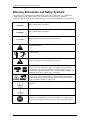
Warning Statements and Safety Symbols...............................................................38
Precautions..............................................................................................................39
Special Installation Notes .......................................................................................40
5 Installation..............................................................................................................42
CPS6000 Installation ..............................................................................................42
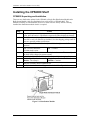
Installing the CPS6000 Shelf..................................................................................43
Install the CPS6000 Shelf .......................................................................................45
Controller ................................................................................................................46
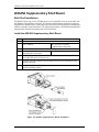
QS845A Supplementary Shelf Board .....................................................................48
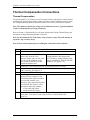
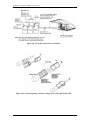
Thermal Compensation Connections......................................................................50
Office Alarms..........................................................................................................54
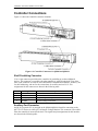
Controller Connections ...........................................................................................55
AC Connections......................................................................................................55
C.O. Ground Conductor Installation.......................................................................60
Rectifier Installation................................................................................................61
Ringer Installation...................................................................................................62
Battery Strings Installation .....................................................................................66
Load Connections ...................................................................................................69
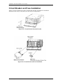
Circuit Breaker and Fuse Installation .....................................................................75
Terminate Load Connections - Direct to Bus Connections ....................................76
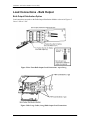
Load Connections - Bulk Output ............................................................................77
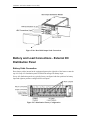
Battery and Load Connections - External DC Distribution Panel ..........................78
Initial Start-up .........................................................................................................84
6 AC, Alarm, and Control Cable Reference Information.....................................87
Overview.................................................................................................................87
AC Utility Connection ............................................................................................87
Controller Connections ...........................................................................................88

CPS6000 –48V Indoor/Outdoor Power Shelf
Issue 16 May 2006 4
Auxiliary Alarms ....................................................................................................90
Additional Bulk Output Module Connections ........................................................91
7A QS840A System Controller ................................................................................92
Overview.................................................................................................................92
CPS6000 Controller Minimum Configuration........................................................98
User Interface and Display......................................................................................98
Minimum Configuration.........................................................................................98
7B QS841A System Controller ..............................................................................108
Overview...............................................................................................................108
Status.....................................................................................................................117
Control/Operations................................................................................................120
Configuration ........................................................................................................121
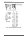
10/100 Base-T Ethernet Port.................................................................................128
8 Rectifier.................................................................................................................135
Overview...............................................................................................................135
Alarms and Displays.............................................................................................136
Features and Functions .........................................................................................138
9 QS872A Distribution Monitoring Module.........................................................139
Overview...............................................................................................................139
10 Ringer Chassis and Ringers ..............................................................................141
Ringer Chassis ......................................................................................................141
Ringer....................................................................................................................142
Types of Ringing...................................................................................................143
11 Peripheral Devices .............................................................................................146
Voltage/Thermal Probes .......................................................................................146
Remote Voltage Monitor Module.........................................................................147
12 ES772A Remote Distribution Module..............................................................149
Overview...............................................................................................................149
Module Features....................................................................................................151
Module Connector Definitions .............................................................................152
22-position external distribution panel .................................................................159
13 Troubleshooting .................................................................................................160
Checking for Defective VT-Probes ......................................................................162
14 Product Warranty..............................................................................................163
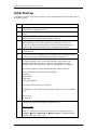
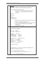
Appendix A: T1.317 Command Language ...........................................................165
Initializing the QS840A Controller.......................................................................165
T1.317 Command Language.................................................................................166
Appendix B: Battery Functions .............................................................................190
Float Mode............................................................................................................190
Slope Thermal Compensation...............................................................................190
Plant Battery Test..................................................................................................193
Boost Mode...........................................................................................................194
Appendix C: Alarms and Relays ...........................................................................197
Alarm Relays ........................................................................................................197
Alarms...................................................................................................................197
Appendix D: EasyView for Windows® for the CPS6000 Controller.................202

CPS6000 –48V Indoor/Outdoor Power Shelf
Issue 16 May 2006 5
Overview...............................................................................................................202
Loading the EasyView Application......................................................................202
Making the Connection.........................................................................................202
Configuring a Site.................................................................................................203
Serial Port Setup ...................................................................................................203
Connect to Site......................................................................................................203
Navigating Once Connected .................................................................................204
Appendix E: Pigtail Alarm Cable..........................................................................206
Appendix F: Operating Temperature Measurement and Vertical Spacing......209
Overview...............................................................................................................209
Revision History......................................................................................................210

CPS6000 –48V Indoor/Outdoor Power Shelf
Issue 16 May 2006 6
1 Introduction
Overview
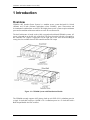
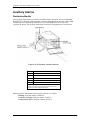
CPS6000 -48V Outdoor Power System is a modular power system designed for 19-inch
(483mm) and 23-inch (584mm) applications where reliability, space conservation and
environmental considerations are critical. This highly dense power system occupies minimum
space and its modular architecture enables an exact fit to custom needs.
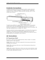
The shelf architecture is based on the widely accepted and acclaimed CPS4000 systems. AC
power is brought in on the left side of the shelf. The first slot on the left side is occupied by
the controller. DC Output is aggregated on the right side of the shelf. Rectifiers/Ringers
occupy the slots available between the controller and the DC output
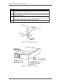
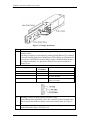
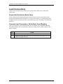
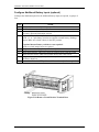
Figure 1-1: CPS6000 System with Distribution Module
The CPS6000 currently supports -48V primary loads up to 8.2kW of N+1 redundant power in
a single 19-inch shelf, and up to 10.9kW of N+1 redundant power in a 23-inch shelf with a
Bulk Output Module and 50A rectifiers.

CPS6000 –48V Indoor/Outdoor Power Shelf
Issue 16 May 2006 7
CPS6000 systems may include up to 4 bulk-output shelves: an Initial shelf with controller,
and up to three supplemental shelves. External distribution is used with multi-shelf systems.
Ringer Chassis may be installed in Power Slots. Each Ringer Chassis supports one ringing
output in either non-redundant (simplex) or 1 + 1 redundant (duplex) operation. Ringer
distribution is direct from the Ringer Chassis.
The system controller card is powered by the system bus voltage and is located on the left
side of the shelf. The controller allows setting of system parameters, and various alarm
thresholds locally on the four-line LCD graphics display with intuitive navigation. The
controller can perform periodic battery tests and has a provision for user-definable alarm
inputs as well as alarm relays.
Applications
CPS6000 fits digital loop carrier, remote switch, fiber in the loop, cable television cabinets,
Intelligent Vehicle Highway System (IVHS), Personal Communications Service (PCS),
cellular, and customer premises applications.

CPS6000 –48V Indoor/Outdoor Power Shelf
Issue 16 May 2006 8
Customer Service Contacts
Customer Service, Technical Support, Product Repair and Return,
and Warranty Service
For customers in the United States, Canada, Puerto Rico, and the US Virgin Islands, call 1-
800-THE-1PWR (1-800-843-1797). This number is staffed from 7:00 am to 5:00 pm Central
Time (zone 6), Monday through Friday, on normal business days. At other times this number
is still available, but for emergencies only. Services provided through this contact include
initiating the spare parts procurement process, ordering documents, product warranty
administration, and providing other product and service information.
For other customers worldwide the 800 number may be accessed after first dialing the AT&T
Direct country code for the country where the call is originating, or you may contact your
local field support center or your sales representative to discuss your specific needs.
Customer Training
Tyco Electronics offers customer training on many Power Systems products. For information
call 1-972-284-2163. This number is answered from 8:00 a.m. until 4:30 p.m., Central Time
Zone (Zone 6), Monday through Friday.
Downloads and Software
To download the latest product information, product software and software upgrades, visit our
web site at http://power.tycoelectronics.com/

CPS6000 –48V Indoor/Outdoor Power Shelf
Issue 16 May 2006 9
2 Product Description
CPS6000 System Overview
CPS6000 power systems are comprised of shelves, rectifiers, ringer chassis, ringers, and
distribution modules. Several types of distribution modules are available. The Bulk Output
Module provides connection to an external distribution without consuming a shelf power slot.
The CPS6000 is available as single-shelf systems and multiple-shelf systems with both 19-
inch and 23-inch shelves.
Single Shelf Systems
• With Distribution Module: all components contained in single shelf.
• With Bulk Output Module: uses external distribution, accommodates all other
components within the shelf.
Multi-Shelf Systems
• With Bulk Output Module: uses external distribution, accommodates all other
components within the shelves.
AC power is supplied to the rectifiers which produce regulated -48V dc output voltage. This
voltage is used to power all other system components including ringers, the system controller
and the LVD boards. Batteries are connected to distribution, internal or external. Some
Distribution Modules provide battery circuit breakers. Single-Slot and Double-Slot
Distribution Module options include GMT-style fuses and bullet-style circuit breakers.
Ringer Chassis may be installed in Power Slots. Each Ringer Chassis supports one ringing
output in either non-redundant (simplex) or 1 + 1 redundant (duplex) operation. Ringer
distribution is direct from the Ringer Chassis. Ringers power ringing signaling outputs and
are powered by -48Vdc.
The batteries are monitored by the system controller to ensure their peak performance and
longevity against thermal issues. They are monitored via the Voltage/Thermal Probes (VT-
Probes), which are connected from the Distribution Module to the battery.
The Remote Voltage Monitor (RVM) module may be used with the VT-Probes in making
voltage measurements for battery string-voltage imbalance detection. Additional VT-Probes
may used by connecting them in a daisy-chain fashion.
The system controller monitors all system parameters and performs battery management
functions. It communicates with all devices using the RS-485 bus. The RVM and VT-Probe
communicate with the controller using the 1-Wire® from Maxim Integrated Products, Inc.
The LVBD contactor is used to connect the battery strings to the main power bus. Under ac
fail conditions, the battery current will be flowing through the contactor to the output

CPS6000 –48V Indoor/Outdoor Power Shelf
Issue 16 May 2006 10
distribution in supporting the load. To prevent deep discharge of batteries, the CPS6000 can
disconnect the batteries from the load by opening the LVBD contactor.
CPS6000 also offers an optional low voltage load disconnect (LVLD) contactor. Non-critical
loads and loads sensitive to low voltages can be connected to the system via the LVLD in the
Distribution Module. CPS6000 disconnects these loads at a set threshold during a battery
discharge. This reduces drain on the batteries and extends reserve time available for critical
loads.
With the Bulk Output Module, a supplementary shelf may be paralleled to the primary shelf
to create a larger plant. Only the primary shelf would contain the system controller. The
supplementary shelf only requires signal connections to the primary shelf, and power
connections to an external distribution panel. The controller can monitor for open protectors,
current from a battery shunt, and monitor and control a low voltage disconnect contactor via
the Remote Distribution Module (RDM).
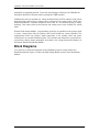
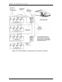
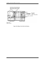
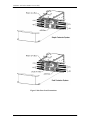
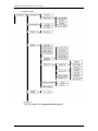
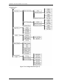
Block Diagrams
2-1a and 2-1b are basic block diagrams of the CPS6000 System in a single shelf with a
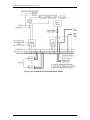
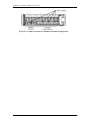
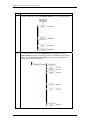
Distribution Module. Figure 2-2 shows the Bulk Output Module in place of the Distribution
Module.

CPS6000 –48V Indoor/Outdoor Power Shelf
Issue 16 May 2006 11
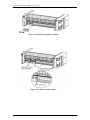
Figure 2-1a: CPS6000 System with Distribution Module

CPS6000 –48V Indoor/Outdoor Power Shelf
Issue 16 May 2006 12
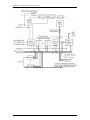
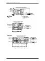
Figure 2-1b: CPS6000 System with Distribution Module

CPS6000 –48V Indoor/Outdoor Power Shelf
Issue 16 May 2006 13
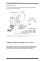
Figure 2-2: CPS6000 System with Bulk Output Module
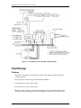
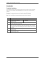
Shelf Design
Features
• The shelf is available in 19-inch (phase 2) and 23-inch standard widths and has the
following features:
• Accepts plug-in rectifier, ringer and Distribution Modules.
• 19-inch shelves provide 4 Power Slots.
• 23-inch shelves provide 5 Power Slots
• Rectifiers, Ringer Chassis, and Distribution Modules may be installed in Power Slots.
Permits growth of plant capacity and easy maintenance without service interruption.

CPS6000 –48V Indoor/Outdoor Power Shelf
Issue 16 May 2006 14
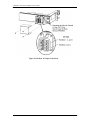
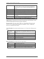
Configurations
The 19-Inch Shelf provides four Power Slots.
The 23-Inch Shelf provides five Power Slots.
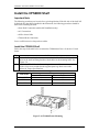
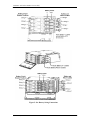
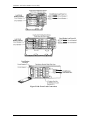
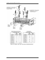
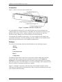
Power Slots support Rectifiers, Ringer Chassis, and Distribution Modules. Figure 2-3 shows
the show the locations of the CPS6000 components in the19-inch and 23-inch shelves with
the Single-Slot Distribution Module.
Figure 2-3: CPS6000 Systems with Single-Slot Distribution Module

CPS6000 –48V Indoor/Outdoor Power Shelf
Issue 16 May 2006 15
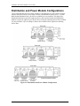
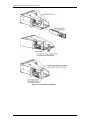
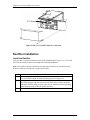
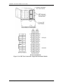
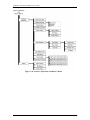
Distribution and Power Module Configurations
The 19-inch shelf has four Power Slots, and the 23-inch shelf has five Power Slots for power
modules (Rectifiers and up to two Ringer Chassis) and distribution options (See 2- 4). With
Bulk Output Distribution only, all slots are available for power modules. The Single-Slot
Distribution Module occupies the right-most Power Slot, and the Double-Slot Distribution
Module occupies the right-most two Power Slots, leaving the remaining Power Slots available
for power modules. Up to two Ringer Chassis can be installed in the right-most remaining
Power Slots.
Figure 2-4: Distribution and Power Module Configurations

CPS6000 –48V Indoor/Outdoor Power Shelf
Issue 16 May 2006 16
Battery Reserve System
Introduction
A battery reserve system is a key component for a reliable power system. The CPS6000
provides a primary voltage of -48Vdc that drives load equipment. At the same time, it
provides float and recharge capability for the battery reserve system. If an ac power failure
occurs, the batteries provide power to the load equipment until the ac can be restored.
Types of Batteries
CPS6000 may be used with valve-regulated lead-acid (VRLA) batteries. Up to four strings of
VR-type batteries or equivalent general trade batteries may be connected directly to a
CPS6000 shelf.
Certain Nickel-Cadmium (Ni-Cd) and Lithium-Ion batteries may also be used with the
CPS6000. Please contact your sales representative for details. CPS6000 is also compatible to
Flooded lead-acid batteries.
See Appendix D for detailed descriptions of battery related functions; float and boost
charging, thermal compensation, and system battery test functions.

CPS6000 –48V Indoor/Outdoor Power Shelf
Issue 16 May 2006 17
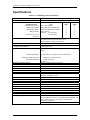
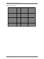
Specifications
Table 2-A: CPS6000 System Specifications
Shelf Single 19-inch or 23-inch shelf
Power Slots per Shelf 4 (19-inch shelf), 5 (23-inch shelf)
Power Units
Installed Position
5
Unit
Max. per
Shelf
Power Slots
Each
Installed from the Right
Bulk Output Module
Distribution Module
Ringer Chassis
Installed from the Left
Rectifiers
Bulk Output Module
Single-Slot Distribution Module
Double-Slot Distribution Module
Ringer Chassis
Rectifiers (19-inch shelf)
(23-inch shelf)
1
1
1
2
4
5
0
1
2
1
1
1
Rectifier Input Distribution Dual ac input (19 and 23-inch shelves)
Individual ac input (19 and 23-inch shelves)
Single ac input (19 and 23-inch shelves)
System Architecture Primary output: 1 primary output power bus per shelf
Primary Power Bus Current
with Bulk Output Module
19-inch shelf: 227A
23-inch shelf: 283A
Output Distribution Primary Bus
Bulk Output Module
Single-Slot and Double-Slot
Distribution Modules
Battery connections: double-hole lugs to terminate battery
strings.
-48 Vdc bulk power outputs to loads or distribution
• Bullet-style circuit breakers
• GMT-style fuses
See Note 2.
Maximum Discharge Current Based on rectifier capacity. See Note 2
Maximum Recharge Current Installed shelf –48V rectifier capacity minus plant –48V load
Operating Ambient Temperature -40 to 75 °C (-40 to 167 °F), see Note 3
Altitude -200 to 13,000 feet (-61 to 3962 meters). See Note 4
Humidity 10% to 95% non-condensing
Audible Noise < 60 dBA
Radiated and Conducted Emissions FCC Part 15, Class B
EN55022 (CISPR22), Class B
Harmonics EN61000-3-2 (IEC61000-3-2)
Voltage Fluctuations EN61000-3-3 (IEC61000-3-3)
Electromagnetic Immunity Meets Telcordia GR-1089-CORE
Electrostatic Discharge EN61000-4-2 Level 3
RF Immunity IEC61000-4-3 Level 3, 10 V/m
EFT IEC61000-4-4 Level 3, No Error; Level 4, No Damage
Surge IEC 61000-4-5 Level 3, No Error; Level 4, No Damage
Conducted Immunity IEC 61000-4-6 Level 3, 10V
Voltage Dips, Interruptions, and Variations IEC 61000-4-11
Earthquake Rating Zone 4, upper floors
Underwriters Laboratories (UL) Listed per Subject Letter 1801:
Power Distribution Center for Communications Equipment, and
cUL Certified (CSA 22.2 950): Safety of Information
Technology Equipment
Safety Agency Approval
VDE licensed to VDE0805/EN60950

CPS6000 –48V Indoor/Outdoor Power Shelf
Issue 16 May 2006 18
Rectifiers are individually UL Recognized (UL1950), cUL
Certified (CSA 22.2 234) or evaluated to EN60950 by an EC
Notified Body, as appropriate.
European Economic Community (EEC)
Directives
EMC Directive 89/336/EEC
Low Voltage Directive 73/23/EEC as amended by Marking
Directive 93/68/EEC
Note 1: CPS6000 can be used with four strings of batteries depending on Distribution Module
Note 2: When used with Single-Slot and Double-Slot Distribution Modules, maximum output is limited to
200A or the size of the LVD contactor installed (if smaller). See Section 3 for limitations on
maximum currents through Distribution Modules.
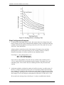
Note 3: Operating temperatures and required airflow are different when used with specific rectifiers. See
Tables 2-D through 2-F for rectifier information.
Note 4: For altitudes above 5000 feet, derate the temperature by 3.6 °F per 1000 feet. For altitudes above
1524 meters, derate the temperature by 0.656 degrees Celsius per 100 meters.
Note 5: Power Unit Install Positions:
• Install these units in order beginning with the right most Power Slot
First: Distribution Module
Second: Ringer Chassis
• Install these units in order beginning with the left most Power Slot
First: Rectifiers
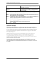
Installation Category
CPS6000 is suitable for connection to ac utility systems where the expected level of lightning
surges complies with ANSI C62.41 Category B or IEC 60664-1 Overvoltage Category II.
A service entrance surge protector is required in applications where the installation categories
can not be classified as being compliant to either ANSI C62.41 Category B or IEC 60664-1
Overvoltage Category II.
CPS6000 rectifiers have been tested for repeated lightning surges typically found in an
Overvoltage Category III installation; however, a service entrance surge protector is
recommended in cabinet applications to bring the power feeds in compliance to the
installation categories above. The service entrance protection should be coordinated with the
protection provided in the power modules.
The power module provides common-mode protection via a 320V MOV in series with a
2500V gas-discharge device and differential-mode protection via a 320V MOV in series with
a 3.5A fuse.

CPS6000 –48V Indoor/Outdoor Power Shelf
Issue 16 May 2006 19
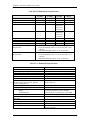
Table 2-B: CPS6000 Physical Specifications
Height
in. (mm)
Width
in. (mm)
Depth
in. (mm)
Weight
lb (kg)
Rectifier 3.41 (86.6) 3.4 (86.3) 11.2 (284.5) 5.75 (2.6)
Ringer Chassis 3.41 (86.6) 3.4 (86.3) 11.2 (284.5) 3.45 (1.6)
Ringer 2.4 (61.0) 1.51 (38.4) 9.9 (252) 1.25 (0.6)
19-Inch Shelf 3.41 (86.6) 17.37 (441.2) 12 (304) –
front access
13.25 (337)-
rear access
7.5 (3.41)
23-Inch Shelf 3.41 (86.6) 20.95 (532.1) 12 (304) –
front access
13.25 (337)-
rear access
12.7 (5.77)
Single-Slot Distribution Module 3.41 (86.6) 5.1 (129.5) 12 (304) 9 (4.1)
Double-Slot Distribution Module 3.41 (86.6) 8.5 (216) 12 (304) TBM
Bulk Output Module 3.41 (86.6) 1.59 (40.4) 12 (304) 4 (1.8)
23-Inch Frame Mounting
Requirements
Standard 23 and 26-inch relay racks:
•Vertical mounting centers: 1.0 in. (25 mm) and 1.75 in.
(44 mm)
•Horizontal mounting centers: 22.32 in. (567 mm)
19-Inch Frame Mounting
Requirements
Standard 19-inch relay racks:
•Vertical mounting centers: 1.0 in. (25 mm) and 1.75 in.
(44 mm)
•Horizontal mounting centers: 18.31 in. (465 mm)
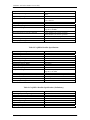
Table 2-C: CPS6000 Shelf Specifications
Control Unit QS840A / QS841A
Nominal Output Voltages 48/52/54.5 Vdc
Operating Voltage Range 42 to 58 Vdc
Maximum Output Current 200A per 19-inch shelf; 250A per 23-inch shelf
(see Note 1)
Nominal Input Voltage 100/120/200/208/240 Vac
Input Voltage Ranges 85 to 275 Vac
Max Nominal Input Current per Rectifier (based
on 25A rectifier for low line ac, and 50A
rectifier for high line ac)
13A at 120 Vac
14.5A at 208 Vac
Boost Voltage 48 to 58 Vdc
Output Voltage Regulation ±0.5%
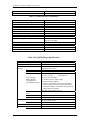
Output Noise:
Ripple
Wideband Noise
100 mVrms maximum, 10 Hz to 20 MHz
< 250 mV pk-pk over the range dc to 100 MHz
Load Share Accuracy 1.5A (maximum) for QS862A
Maximum Discharge Current
(see Note)
227A per 19-inch shelf; 284A per 23-inch shelf
Maximum Recharge Current Installed rectifier capacity minus plant load
Low-Voltage Disconnect 39 to 50 Vdc
Low-Voltage Reconnect 39 to 55 Vdc
Heat Dissipation 177W (604 BTU) per QS862A at full load and
120 Vac operation;

CPS6000 –48V Indoor/Outdoor Power Shelf
Issue 16 May 2006 20
132W (450 BTU) per QS861A rectifier at full
load and 120 Vac operation;
212W (724 BTU) per QS862A at full load and
240 Vac operation;
130W (445 BTU) per QS861A rectifier at full
load and 240 Vac operation;
267W (911 BTU) per QS865A rectifier at full
load and 240 Vac operation;
Power Factor > 0.98 for loads > 50% of full load
Note: Maximum current is based on Bulk Output Module and 50A QS865A rectifier. System capacity
will decrease with lower rated rectifiers.
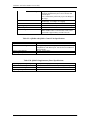
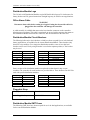
Power Slots Available for Rectifiers or Ringer Chassis
Distribution Module
Shelf
None (Bulk Output Module)
Single-Wide Double-Wide
19-Inch Shelf 4 3 2
23-Inch Shelf 5 4 3
Rectifiers
Table 2-D: QS860A Rectifier Specifications (Preliminary)
Nominal Output Voltage 48/52/54.5 Vdc
Operating Output Voltage Ranges 42 to 58 Vdc
Boost Voltage 48 to 58 Vdc
Output Current 0 to 9.2A at 54.5V
Nominal Input Voltage 100/120/200/208/240 Vac (Shutdown from 135 to
150V)
Input Voltage Ranges 85 to 275 Vac
Input Current 4.9A at 120 Vac
2.9A at 208 Vac
Operating Frequency Range 45 to 66 Hz
Operating Temperature -40 to +75 °C
Output Voltage Regulation ±0.5%
Output Noise, Ripple 250 millivolts peak to peak maximum, over the
range dc to 100 MHz
Load Share Accuracy 1.5A maximum deviation between rectifiers
Heat Dissipation (per rectifier, full load) 108W (369 BTU) at 120 Vac operation
100W (341 BTU) at 240 Vac operation
Power Factor >0.98 (low-line), >0.98 (high line)
Selective High-Voltage Shutdown Above 58 Vdc
Backup High-Voltage Shutdown Above 60 Vdc for 1 millisecond
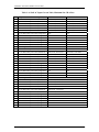
Table 2-E: QS861A Rectifier Specifications
Nominal Output Voltage 48/52/54.5 Vdc
Operating Output Voltage Ranges 42 to 58 Vdc
Boost Voltage 48 to 58 Vdc
Page is loading ...
Page is loading ...
Page is loading ...
Page is loading ...
Page is loading ...
Page is loading ...
Page is loading ...
Page is loading ...
Page is loading ...
Page is loading ...
Page is loading ...
Page is loading ...
Page is loading ...
Page is loading ...
Page is loading ...
Page is loading ...
Page is loading ...
Page is loading ...
Page is loading ...
Page is loading ...
Page is loading ...
Page is loading ...
Page is loading ...
Page is loading ...
Page is loading ...
Page is loading ...
Page is loading ...
Page is loading ...
Page is loading ...
Page is loading ...
Page is loading ...
Page is loading ...
Page is loading ...
Page is loading ...
Page is loading ...
Page is loading ...
Page is loading ...
Page is loading ...
Page is loading ...
Page is loading ...
Page is loading ...
Page is loading ...
Page is loading ...
Page is loading ...
Page is loading ...
Page is loading ...
Page is loading ...
Page is loading ...
Page is loading ...
Page is loading ...
Page is loading ...
Page is loading ...
Page is loading ...
Page is loading ...
Page is loading ...
Page is loading ...
Page is loading ...
Page is loading ...
Page is loading ...
Page is loading ...
Page is loading ...
Page is loading ...
Page is loading ...
Page is loading ...
Page is loading ...
Page is loading ...
Page is loading ...
Page is loading ...
Page is loading ...
Page is loading ...
Page is loading ...
Page is loading ...
Page is loading ...
Page is loading ...
Page is loading ...
Page is loading ...
Page is loading ...
Page is loading ...
Page is loading ...
Page is loading ...
Page is loading ...
Page is loading ...
Page is loading ...
Page is loading ...
Page is loading ...
Page is loading ...
-
 1
1
-
 2
2
-
 3
3
-
 4
4
-
 5
5
-
 6
6
-
 7
7
-
 8
8
-
 9
9
-
 10
10
-
 11
11
-
 12
12
-
 13
13
-
 14
14
-
 15
15
-
 16
16
-
 17
17
-
 18
18
-
 19
19
-
 20
20
-
 21
21
-
 22
22
-
 23
23
-
 24
24
-
 25
25
-
 26
26
-
 27
27
-
 28
28
-
 29
29
-
 30
30
-
 31
31
-
 32
32
-
 33
33
-
 34
34
-
 35
35
-
 36
36
-
 37
37
-
 38
38
-
 39
39
-
 40
40
-
 41
41
-
 42
42
-
 43
43
-
 44
44
-
 45
45
-
 46
46
-
 47
47
-
 48
48
-
 49
49
-
 50
50
-
 51
51
-
 52
52
-
 53
53
-
 54
54
-
 55
55
-
 56
56
-
 57
57
-
 58
58
-
 59
59
-
 60
60
-
 61
61
-
 62
62
-
 63
63
-
 64
64
-
 65
65
-
 66
66
-
 67
67
-
 68
68
-
 69
69
-
 70
70
-
 71
71
-
 72
72
-
 73
73
-
 74
74
-
 75
75
-
 76
76
-
 77
77
-
 78
78
-
 79
79
-
 80
80
-
 81
81
-
 82
82
-
 83
83
-
 84
84
-
 85
85
-
 86
86
-
 87
87
-
 88
88
-
 89
89
-
 90
90
-
 91
91
-
 92
92
-
 93
93
-
 94
94
-
 95
95
-
 96
96
-
 97
97
-
 98
98
-
 99
99
-
 100
100
-
 101
101
-
 102
102
-
 103
103
-
 104
104
-
 105
105
-
 106
106


Ask a question and I''ll find the answer in the document
Finding information in a document is now easier with AI
Other documents
-
Edsal XCP100 Assembly Manual
-
Pass and Seymour RF26252CD User guide
-
Alpha Cordex 030-728 Installation & Operation Manual
-
 Alpha Technologies Cordex 24 User manual
-
Transition Networks VDC-TO-12VDC User manual
-
-
Emerson NetSure 211 Series Ordering Guides
-
Delta Electronics MCS-1800 User manual
-
ICT Digital Series Owner's manual
-
