
IS 2.5
MANUALE USO E MANUTENZIONE
USAGE AND MAINTENANCE MANUAL
MANUEL D'INSTRUCTION ET D'ENTRETIEN
GEBRAUCHSANWEISUNG UND
WARTUNGSVORSCHRIFTEN
MANUAL USO Y MANTENIMENTO
GEBRUIKS- EN ONDERHOUDSHANDLEIDING
Rev.2 M.C. 27-11-2001 Cod. 41977
masemase
masemase
mase
GENERATORS
I
GB
F
D
E
NL

IS 2.5
2
GENERATORS
NR.000000
mase GENERATORS S.p.A.
Tel. +39 (0) 547 354311
Fax +39 (0) 547 317555
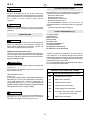
DICHIARAZIONE CE DI CONFORMITÀ
EC DECLARATION OF CONFORMITY
Fabbricante/Manufacturer: mase GENERATORS S.p.A.
Indirizzo /Address : Via Tortona 345, Pievesestina (FC)
Il sottoscritto Luigi Foresti in qualità di direttore tecnico della mase GENERATORS S.p.A., dichiara sotto la
propria responsabilità che il gruppo elettrogeno modello .................... :
The undersigned Luigi Foresti as mase GENERATORS S.p.A. technical manager declares, under his sole
responsability, that the generator model................:
Codice / Code Descrizione / Model Matricola / Serial N.
E' conforme alle disposizioni delle Direttive di seguito elencate :
CEE 89/392 (come emendata delle Direttive CEE 91/368 e CEE 93/44)
CEE 89/336 (come emendata delle Direttive CEE 92/31)
CEE 73/23 modificata da CEE 93/68.
Corresponds to the requirements of the following EEC Directives :
89/392/EEC (as amended by the Directive 91/368/EEC and 93/44/EEC)
89/336/EEC (as amended by the Directive 92/31/EEC )
73/23//EEC as amended by 93/68/EEC.
mase GENERATORS S.p.A. Sede legale ed Amm.: 47023 CESENA (FC) ITALY - Via Tortona, 345 - C.F./P.I. 00687150409 Cap. Soc. milioni 2000
di cui 949 versati - Registro Società Tribunale Forl' n. 6818 - CCIAA Forl' n.164063 - c.c.p. n. 11541471 - EXPORT FO n. 006368
Cesena, / /
......................................................
Direttore Tecnico
Technical Director
Page is loading ...
Page is loading ...
Page is loading ...

IS 2.5
6
GENERATORS
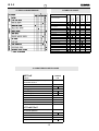
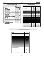
MOTORE-ALTERNATORE - MOTEUR-ALTERNATEUR - ENGINE-ALTERNATOR - MOTOR-GENERATOR
5LI &RG 4W\ 'HVFUL]LRQH 'HVFULSWLRQ
1 70821 1 Asta livello olio Oil dipstick
2 90905 1 Scatola filtro Air filter box
3 70812 1 Massa filtrante Sponge
4 10807 1 Portagomma Nipple
5 61156 1 Collettore filtro aria Manifold
6 8584 1 Bocchettone carico olio Filler
7 10808 1 Sede asta olio Fitting
8 30647 1 Elettrovalvola Fuel solenoid
9 70822 1 Tappo carico olio Oil cap
10 10822 1 Curva scarico Fitting
11 70543 cm 30 Tubo gasolio Pipe
12 70442 cm 25 Tubo acqua d.15 Pipe
13 70237 cm 25 Tubo gasolio Pipe
14 10812 1 Portagomma Nipple
15 10813 1 Raccordo Fitting
16 61157 1 Gomito miscelatore Exhaust manifold
17 30253 1 Sonda temp. acqua 70 °C Thermostat
18 80120 1 Sonda temp. cilindro Thermostat
19 31001 1 Pompa acqua mare Sea water pump

7
GENERATORS
IS 2.5
Rif. Cod. Qty. Descrizione Description
20 50257 1 Puleggia pompa 50 Hz Pulley
20 50260 1 Puleggia pompa 60 Hz Pulley
21 70823 1 Manicotto carico olio Oil pipe
22 70824 1 Manicotto acqua Water pipe
23 10814 1 Gomito ottone Fitting
24 10614 2 Portagomma Nipple
25 10615 1 Puleggia Pulley
26 70807 1 Cinghia 50 Hz Belt
26 70863 1 Cinghia 60 Hz Belt
27 03767 1 Coperchio alternatore Cover
28 10610 1 Tirante centrale Central tie rod
29 013093 1 Rotore Rotor
30 910589 2 Diodo rotore Diode
31 20521 2 Varistore Varistor
32 013049 1 Statore 115/230V 50Hz Stator 115/230V 50Hz
32 04262 1 Statore 120/240V 60Hz Stator 120/240V 60Hz
33 70647 1 Passacavo Cable guide
34 81103 1 Cuscinetto Bearing
35 71169 2 Tubo carburante Fuel Pipe
36 012806 1 Coperchio alternatore Cover
37 10284 4 Tirante alternatore Tie rod
38 10464 1 Rondella con guida Washer
39 31004 1 Pompa gasolio Diesel pump
40 07050 1 Cablaggio motore Electrical assy
41 61158 1 Staffa antivibranti Bracket
42 61159 1 Staffa antivibranti Bracket
43 61162 1 Supporto pompa Pump bracket
44 61163 1 Piastrina supporto pompa Plate
45 07166 1 Staffa elettrovalvola Bracket
46 013145 1 Protezione alternatore Protection
47 70634 4 Antivibrante 30x30 Shock absorber
48 70808 1 Cuffia in gomma Rubber cover
49 70802 1 Cuffia in gomma Rubber cover
50 70616 cm70 Guarnizione adesiva 10x15 Gasket
51 70629 cm25 Tubo d.25 Pipe
52 10823 7 Dado Oteco Nut
53 10794 2 Fascetta 30x60 Clamp
54 10825 6 Fascetta 16x25 Clamp
55 90906 1 Parete divisoria Panel
56 97539 1 Raccordo elettrovalvola Fitting
57 71151 1 Guarnizione OR Or gasket
58 10842 2 Fascetta 10x15 Clamp
59 92623 1 Girante pompa Jota Impeller for Jota pump
59 80161 1 Girante pompa Jhonson Impeller Jhonson pump
60 97537 1 Pressostato olio Oil pressure switch
61 11374 2 Portagomma nafta Fuel Nipple
62 70185 1 Guarniz. OR O-Ring gasket
63 92456 1 Guarniz. pompa acqua Jota Jota pump O-Ring
63 93312 1 Guarniz. pompa Johnson Johnson pump gasket
64 97601 1 Guarnizione scarico Gasket
65 10166 1 Vite Screw
66 10791 2 Fascetta Clamp
67 012485 1 Staffa supporto termico Bracket
68 71228 1 Cappuccio Cover
69 32714 1 Interruttore termico 2P 10 A Thermal switch 2P 10 A
70 03757 1 Motore Yanmar L48 50Hz Yanmar L48 Engine 50Hz
70 011774 1 Motore Yanmar L48 60Hz Yanmar L48 Engine 60Hz

IS 2.5
8
GENERATORS
CASSA INSONORIZZANTE CHASSIS FRAME RAHMEN
b
c
a
d
29
30
31
28
32
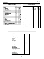
1 80542 1 Regolatore carica batt. Batt. charger regulator
2 31188 1 Condensatore Capacitor
3 31002 1 Fusibile lamellare 20 A Fuse 20 A
4 30925 1 Portafusibile Fuse carrier
5 30926 1 Piastrina portafusibili Fuse holder terminal
6 32690 1 Scheda relè Relay board
7 61181 1 Radiatore acqua/aria Water/Air intercooler
8a 90902 1 Coperchio cassa sup. Soundproof box cover
8b 90903 1 Coperchio cassa post. Soundproof box cover
8c 12759 1 Fondo cassa Soundproof box bottom
8d 70881 1 Scatola scheda relè Relay box cover
9 611160 2 Staffa fondo cassa Bracket
10 07529 1 Supporto scambiatore Water/Air intercooler support
11 70733 8 Elastomero Shock absorber
12 10780 4 Distanziale Spacer
13 70739 2.7 mt Profilato in gomma Gasket
14 70809 1 Serie spugne Sponge get
15 10567 1 Passacavo DG48 Cable guide
16 10566 2 Passacavo DG29 Cable guide
17 70799 2 Pressacavo PG 13,5 Cable guide
18 07337 2 Staffa fissaggio cofani Plate
19 10823 7
Dado oteco MUT 986 M6
Nut
21 70800 2 Dado per PG 13,5 Nut
22 80162 1 Zinco Scambiatore Zinc anode
23 04306 4 Cinghietta in gomma Strap
24 10815 4 Fermo cinghietta Plate
25
26 31678 2 Relè Relay
27 70878 1 Paratia lato motore Bulkhead
28 91034 1 Circuito stampato Printed circuit
29 70786 40 cm Guarnizione Gasket
30 70854 1
Scatola pannello comand
Printed circuit box
31 70634 4 Antivibrante 30x30 Shock absorber 30x30
32 07664 1 Comando a distanza Remote control panel
Page is loading ...
Page is loading ...
Page is loading ...
Page is loading ...
Page is loading ...

IS 2.5
14
GENERATORS
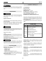
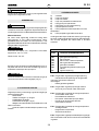
CONTENTS
FIGURES pag.2
TAB."A" TABLE SUGGESTED OILS pag.2
WIRING DIAGRAM pag.4
1 SAFETY REGULATIONS pag.20
2 PRELIMINARY CHECKS pag.20
3 GENERATOR USE pag.20
Starting
Generator Stop
4 SAFETY DEVICES pag.20
Low oil pressure device
Warning
High temperature device
Alternator overload/over temperature device
Important
5 MAINTENANCE pag.21
Important
Engine maintenance
Important
6 INACTIVE PERIOD pag.21
7 CONTROL PANEL pag.21
8 PROTECTION FUSE pag.22
9 DIMENSION AND WEIGHT pag.22
10 DESCRIPTION WIRING DIAGRAM pag.22
11 TROUBLE MAINTENANCE pag.22
12 TROUBLE SHOOTIN pag.22
13 TECHNICAL FEATURES pag.23
DANGER
WARNING
A statement advising of the need to take care lest there be serious consequences resulting in
death of personnel or in hazard to health.
A situation that could occur during the lifetime of a product, system or plant that has the
potential for human injury, damage to property, damage to the environment, or economic loss.
A statement advising of the need to take care lest serious consequences result in harm to
material items such as the asset or the product.
Important information.
Drawing are provided by way of example. Should your machine be quite different from the illustrations contained in
this manual, the safety regulations and relevant information are always granted.
The manufacturer's policy of constant development and updating may lead to modifications without prior notice.
CAUTION
INFORMATION
GB

15
GENERATORS
IS 2.5
CONGRATULATIONS ON HAVING CHOSEN A MASE
PRODUCT
This manual contains all the necessary information for
proper installation and use of the generator. Its essential,
either for the customers safety and satisfaction or for
good reliability of the generator, to carry out proper
installation and a careful pre-delivery test.
A wrong installation or an oversight on testing may
compromise the efficiency of the generator and even
jeopardize the customers safety.
All information and illustrations in this handbook refer to
the latest produced model at the time of printing.
For any further information, please get in touch with the
nearest MASE SERVICE CENTER, theyll be pleased to
help you at any time.
MASE reserve the right to introduce changes without prior
notice. No part or illustration contained in this handbook
can be reproduced without previous approval by MASE
MASE GENERATORS S.p.A.
1 SAFETY REGULATIONS
- Read carefully all the instructions given in this handbook
and in the installation manual; they are of the utmost
importance for correct installation and use of the unit and
for prompt intervention in case of need.
- Do not allow unskilled or untrained people to use the
unit.
- Do not allow children or animals to get close to the
generator while it is working.
- Do not handle the generator or the remote control panel
with wet hands; any misuse may cause electric shocks.
- Any testing of the unit is to be carried out only when the
engine is stopped. Possible checks on the generator
when its running have to be performed only by skilled
workers.
2 PRELIMINARY CHECKS
On starting the generator for the first time and after any
servicing, it is advisable to make sure that:
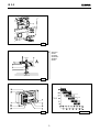
- The oil is at the right level through the rod ref. 1 Fig. 1
, as per table for suggested oils.
- The generator is well secured to the soundproofing box
by means of the proper bolts.
- The electric loads are disconnected so as to avoid
starting the generator on load.
- Every connection (fuel, exhaust, remote control, A.C.,
battery) has been properly carried out and there are no
connections in bad conditions.
- The water cock is open, as per (ref. 2 fig. 2)
- If anon-return valve is used, the cooling circuit from the
valve up to the pump has been manually filled (ref. 1
fig. 2)
3 GENERATOR USE
Before starting the generator, make sure all preliminary
checks, as per item 1 , have been properly carried out
Starting
To start the engine push the button << ON >> (fig. 3 ref.
4), all the pilot and warning lamps will glow for 5 sec. about
in a self control function, later on only the << panel on >>
(fig. 3 ref. 5) and then start the engine pushing the button
<<Start >> (fig. 3 ref.3), for 5 sec. max. Release it only
when the engine runs. A correct generator functioning is
demostrated by the led (fig .3 ref. 6) glowing on. Once
started,the safety devices of the generator are automaticily
activated (see item. 4).
Generator Stop
The generator can be stopped ushing the <<OFF>>
button on the control panel (fig. 3 ref 2).
4 SAFETY DEVICES
The generator has been equipped with a setof safety
devices in case ot any misuse or running trouble, as
follows:
- Low oil-pressure device:
it causes the generator shut-down in case of insufficient
oil pressure. Its intervention is shown by the warning light
going on (fig. 3 Ref. 7). It is usually enough to top up the
oil before starting the generator again.
The low oil-pressure device does not necessarily show
the oil level; a check of the oil level is consequently
necessary at regular intervals.
- High temperature device:
it causes generator shut-down in case of high temperatu-
re of the engine. Its intervention is shown by the warning
light going on (fig.3 ref.8).Should this device come in to
operation,look for and eliminate the causes of the
intervention and then start the generator again.
- Alternator overload/over temperature device:
it comes into operation, stopping the generator, in case
of thermic or electric overload of the alternator.
Its intervention is shown bythe relative warning light going
on (fig. 3 ref. 9). Wait until the temperature of the alternator
windings goes back to the normal values. Its however
recommended to look forand eliminate the causes of the
intervention before starting the generator again.
If one of the above safety devices intervenes, look for and
eliminate the causes of the intervention, then push the <<
STOP >> button to avoid that signal keeps stored.
WARNING
WARNING
GB

IS 2.5
16
GENERATORS
INFORMATION
In case of the two fuses (ref.1/2 Fig.4) got burnt,
a protectio inserts and does not allows the generator to
start.
5 MAINTENANCE
Any servicing is to be carried out with the engine stopped
after it has cooled enough, and only by skilled and
licensed staff.
Engine maintenance
The engine has to be serviced at regular intervals, as
shown in the table:
for any further and more detailed information,please
consult the handbook supplied by the engine
manufacturer, accompanying every generator.
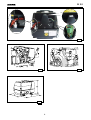
Cheek oil level by means of the proper dipstick (fig. 5 ref.
1) and make sure it is always between the minimum and
maximum levels of the dipstick.
Engine carter capacity:
l. 0.8
Oil topping up and replacement can be carried out through
the hole. (fig. 5 ref. 2).
For changing oil, remove the levelstick and replace oil with
the special pipe. (fig. 5, ref. 3).
We suggest to carry out the draining when the oil is still
warm enough, to allow an easy flowing out.
Beore executing the maintenance on the water-air
exchanger (rif. 3 fig. 6), it is necessary to empty the water
intake circuit throught the special cock.(ref. 3 fig. 2)
6 INACTIVE PERIOD
Should the unit remain unused for a long time, its
necessary to act as follows:
- Replace sump oil.
- Replace oil filter.
- Replace fuel filter.
- Replace the zinc anodes (ref. 1 fig. 6)
- If the room temperature is near or below 0°C it is
indispensable to drain the engine cooling circuit using the
lever cock (ref. 3 fig. 2)
- Lubrificate the water pump impeller.
CAUTION
INFORMATION
WARNING
7 CONTROL PANEL (fig. 3)
1) HOURSMETER
2) OFF BUTTON
3) START BUTTON
4) BUTTON ON
5) PANEL ON LED (GREEN)
6) GENERATOR OUTPUT LED (GREEN)
7) OIL PRESSURE LED (RED)
8) ENGINE TEMPERATURE LED (RED)
9) GENERATOR TEMPERATURE LED (RED)
When the unit stops because a circuit breaker trips, the
operating time indication disappears from the control
panel display and a code appears to indicate the cause
of the generator stop.
In the table below all the codes and their meaning are
listed.
ALARM CODES
CODE CAUSE OF CIRCUIT-BREAKER TRIP
E - 80 No power on generator
E - 81 Low oil pressure
E - 82 High motor temperature
E - 83 High alternator temperature
E - 85 Generator overload
E - 87 At 30" from start unit does not reach 80%
of nominal voltage
batt Low battery
Code E - 80 This code indicates that the unit has
stopped because of no voltage = 0 Volt. When this code
appears, it means:
- that the control panel is unable to measure the
alternator voltage for cut-off of an electrical connection;
- that the alternator is damaged.
Code E - 81 This code indicates that the unit has
stopped because the motor lubrication system pressure
is insufficient.
Code E - 82 This code indicates that the unit has
stopped because the motor has reached too high
temperatures.
Code E - 83 This code indicates that the unit has
stopped because the alternator has reached too high
temperatures.
GB

17
GENERATORS
IS 2.5
Code E - 85 This code indicates that the unit has
stopped because the voltage has dropped to below 70%
of the nominal value for longer than 15 seconds.
Code E - 87 This code indicates that the unit has
stopped because the generator voltage has not reached
80% of the nominal value 30 seconds after starting. This
could be caused by insufficient motor RPM or a broken
alternator.
batt This code indicates that the battery
is low. When this code appears, the generator is not
stopped.
When a circuit breaker has tripped with a consequent
generator stop, the panel must be reset by pressing the
OFF button in order to restart the unit.
If the unit is started and the alternator does not produce
voltage, or the control panel does not read voltage, the
latter switches off completely after one minute, stopping
the unit.
8 PROTECTION FUSE ( fig. 4 )
1) RELAY CIRCUIT FUSE
2) BATTERY CHARGER FUSE
9 DIMENSIONS AND WEIGHT( fig. 7 )
IS 2500
a) Lenght mm.580
b) Width mm.430
c) Height mm.430
Weight Kg. 80
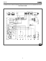
10 DESCRIPTION WIRING DIAGRAM (fig. 8 )
1 ROTOR
2 STATOR
3 DIODE 3A
4 VARISTOR
5 PRINTED CIRCUIT RELAY
6 POWER TERMINAL BOARD
7 RELAY CIRCUIT TERMINAL BOARD
8 CONTROL PANEL TERMINAL BOARD
9 FUSE 1A
10 CAPACITOR
11 BATTERY CHARGER REGULATOR
12 FUSE
13 STARTER
14 BATTERY
15 FUEL PUMP
16 FUEL SOLENOID
17 OIL PRESSURE SWITCH
18 OVERHEAD ENGINE THERMOSTAT
19 WATER TERMOSTAT
20 ALTERNATOR THERMOSTAT
21 MAGNETOTERMIC SWITCH
11 TROUBLE MAINTENANCE
12 TROUBLE SHOOTING
INFORMATION
WARNING
GB
COMPLAINT
PROBABLE REASON
Defective starting buttons
Defective fuel solenoid
Defective battery Battery
cable section
Defective starting motor
Piping fuel filter choked
12V circuit fuse
Avv./Ev.relay
Too much oil in crankcase
Safety device intervention
Overload
Defective governor linkage
Worm valve guides
Blocked valves
Worm cylinder and position rings
Defective injector
Defective injector pump
Defective feeding pump
BLACK SMOCKE
START AND
STOP
UNSTABLE
RUNNING
DOES NOT
START
WHITE SMOCKE

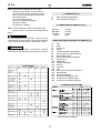
IS 2.5
18
GENERATORS
GB
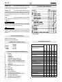
211cc.
70 X 55
3000 3600
230 240
DIESEL
ELECTRIC
0,8 lt.
20°
1700W 1900W
1
F
50 60
1cylinder,4 stroke,internal combustion
air-cooled diesel
Displacement
Model
R.P.M.
Bore for stroke
Power Hp
Fuel consumption g./Hp.h
Starting system
Oil capacity
Max inclination
ALTERNATOR
Continuous output
Power factor
Insulation class
Frequecy Hz
ENGINE
3,8/4,2 4,2/4,7
YANMAR
Fuel
Synchronous,self-excited,single
phase, 2 poles, brushless
13 TECHNICAL FEATURES
L48 AE
Page is loading ...
Page is loading ...
Page is loading ...
Page is loading ...
Page is loading ...
Page is loading ...
Page is loading ...
Page is loading ...
Page is loading ...
Page is loading ...
Page is loading ...
Page is loading ...
Page is loading ...
Page is loading ...
Page is loading ...
Page is loading ...
Page is loading ...
Page is loading ...
Page is loading ...
Page is loading ...
Page is loading ...

Mase Generators S.p.a. • Via Tortona, 345 • 47023 Cesena (FC) ITALY • Tel. (+39) 0547.35.43.11
-
 1
1
-
 2
2
-
 3
3
-
 4
4
-
 5
5
-
 6
6
-
 7
7
-
 8
8
-
 9
9
-
 10
10
-
 11
11
-
 12
12
-
 13
13
-
 14
14
-
 15
15
-
 16
16
-
 17
17
-
 18
18
-
 19
19
-
 20
20
-
 21
21
-
 22
22
-
 23
23
-
 24
24
-
 25
25
-
 26
26
-
 27
27
-
 28
28
-
 29
29
-
 30
30
-
 31
31
-
 32
32
-
 33
33
-
 34
34
-
 35
35
-
 36
36
-
 37
37
-
 38
38
-
 39
39
-
 40
40


Ask a question and I''ll find the answer in the document
Finding information in a document is now easier with AI
in other languages
- italiano: Mase IS 02.5
- français: Mase IS 02.5
- español: Mase IS 02.5
- Deutsch: Mase IS 02.5
- Nederlands: Mase IS 02.5
Related papers
Other documents
-
EINHELL TC-PG 10/E5 Operating Instructions Manual
-
AL-KO 2000i User manual
-
 Rosenbauer RS 9 Operating instructions
-
GEKO Stromerzeuger 2801 E-A/SHBA Operating instructions
-
Sincro FB2 Use and Maintenance Manual
-
 Mosa GE 65 PS SX Owner's manual
-
 Mosa GE 12054 HZDT Owner's manual
-
Parkside PSE 2800 B2 Operating instructions
-
Herkules SE 2200 F Operating Instructions Manual
-
Master BV 70 E Owner's manual


