Page is loading ...

MANUALE USO E MANUTENZIONE
USAGE AND MAINTANCE MANUAL
MANUEL D'INSTRUCTIONS ET D'ENTRETIEN
GEBRAUCHSANWEISUNG UND WARTUNGSVORSCHRIFTEN
MANUAL USO Y MANTENIMENTO
INSTALLATIEHANDLEIDING
REV.1 MC del 18-10-01 Cod. 41963
masemase
masemase
mase
GENERATORS
IS 3.5
IS 4.0
IS 5.0
IS 6.0
Return To Table Of Contents

IS 3.5 - 4.5 - 5.0 - 6.0
- 2 -
MASE GENERATORS S.p.A.
Tel.0547/354311
Fax 0547/317555 (commercial dept.)
Fax 0547/354314 (service dept.)
Fax 0547/317888 -Tlx 550397
NR.000000
DICHIARAZIONE CE DI CONFORMITA'
EC DECLARATION OF CONFORMITY
Fabbricante/Manufacturer: MASE GENERATORS S.p.A.
Indirizzo /Address : Via Tortona 345, Pievesestina (FO)
Il sottoscritto Luigi Foresti in qualità di direttore generale della MASE GENERATORS S.p.A., dichiara sotto la
propria responsabilità che il gruppo elettrogeno modello ......... :
The undersigned Luigi Foresti as MASE GENERATORS S.p.A. general manager declares, under his sole
responsability, that the generators model is..................:
Codice / Code Descrizione / Model Matricola / Serial N.
E' conforme alle disposizioni delle Direttive di seguito elencate :
CEE 89/392 (come emendata delle Direttive CEE 91/368 e CEE 93/44)
CEE 89/336 (come emendata delle Direttive CEE 92/31)
CEE 73/23 modificata da CEE 93/68.
Corresponds to the requirements of the following EEC Directives :
89/392/EEC (as amended by the Directive 91/368/EEC and 93/44/EEC)
89/336/EEC (as amended by the Directive 92/31/EEC )
73/23//EEC as amended by 93/68/EEC.
Cesena, / / ......................................................
Direttore Tecnico
Technical Director
GENERATORS
MASE GENERATORS S.p.A. Sede legale ed Amm.: 47023 CESENA (FO) ITALY - Via Tortona, 345 - C.F./P.I. 00687150409 Cap. Soc. milioni
1250 interamente versato - Registro Società Tribunale Forl' n. 6818 - CCIAA Forl' n.164063 - c.c.p. n. 11541471 - EXPORT FO n. 006368
Return To Table Of Contents

- 3 -
IS 3.5 - 4.5 - 5.0 - 6.0
3
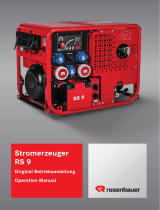
TAB "A"
S.A.E
Service
Grade
-30 -20 -10 0 10 20 30 40
Ambient temperature (
o
C)
40
20W
20W40
20
30
5W
5W30
10W
10W30
A APERTO
OPEN
OUVERT
GEÖFNET
ABIERO
OPEN
2
1
1
Return To Table Of Contents

IS 3.5 - 4.5 - 5.0 - 6.0
- 4 -
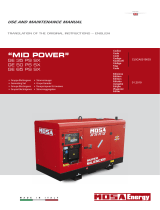
4
6
5
7
1
1
2
C
A B
Return To Table Of Contents

IS 3.5 - 4.0 - 5.0 - 6.0
- 6 -
I
INDICE
Dichiarazione di conformità ................................2
Figure ................................................................3
Schema elettrico ................................................ 5
1 NORME DI SICUREZZA .....................................8
2 CONTROLLI PRELIMINARI ................................8
3 UTILIZZO DEL GENERATORE ........................... 8
Avviamento
Arresto
4 PROTEZIONI ......................................................9
Protezione a bassa pressione olio
Attenzione
Protezione alta temperatura
Protezione sovratemperatura
Sovraccarico alternatore
Importante
5 MANUTENZIONE ............................................. 10
Importante
Manutenzione ordinaria del motore
Importante
6 PERIODO INATTIVITA' ..................................... 10
7 CRUSCOTTO COMANDI .................................. 10
8 FUSIBILI DI PROTEZIONE ............................... 11
9 DIMENSIONI E PESO ..................................... 11
10 DESCRIZIONE SCHEMA ELETTRICO ............. 11
11 TABELLA MANUTENZIONI .............................. 12
12 TABELLA GUASTI ........................................... 12
13 CARATTERISTICHE TECNICHE ...................... 12
Return To Table Of Contents

IS 3.5 - 4.0- 5.0 - 6.0
- 12 -
GB
CONTENTS
FIGURES ...................................................... pag.2
TAB."A" TABLE SUGGESTED OILS............. pag.2
WIRING DIAGRAM ....................................... pag.4
1 SAFETY REGULATIONS .............................. pag.13
2 PRELIMINARY CHECKS .............................. pag.13
3 GENERATOR USE ....................................... pag.13
Starting
Generator Stop
4 SAFETY DEVICES ....................................... pag.13
Low oil pressure device
Warning
High temperature device
Alternator overload/over temperature device
Important
5 MAINTENANCE ............................................ pag.14
Important
Engine maintenance
Important
6 INACTIVE PERIOD ....................................... pag.14
7 CONTROL PANEL ........................................ pag.14
8 PROTECTION FUSE ..................................... pag.8
9 DIMENSION AND WEIGHT ........................... pag.15
10 DESCRIPTION WIRING DIAGRAM ............... pag.15
11 TROUBLE MAINTENANCE ........................... pag.15
12 TROUBLE SHOOTIN ..................................... pag.15
13 TECHNICAL FEATURES .............................. pag.16
A statement advising of the need to take care lest there be serious consequences resulting in
death of personnel or in hazard to health.
A situation that could occur during the lifetime of a product, system or plant that has the
potential for human injury, damage to property, damage to the environment, or economic loss.
A statement advising of the need to take care lest serious consequences result in harm to
material items such as the asset or the product.
Important information.
Drawing are provided by way of example. Should your machine be quite different from the illustrations contained in this
manual, the safety regulations and relevant information are always granted.
The manufacturer's policy of constant development and updating may lead to modifications without prior notice.
DANGER
WARNING
CAUTION
INFORMATION
Return To Table Of Contents

- 13 -
IS 3.5 - 4.0- 5.0 - 6.0
GB
CONGRATULATIONS ON HAVING CHOSEN A MASE
PRODUCT
This manual contains all the necessary information for
proper installation and use of the generator. It’s essential,
either for the customer’s safety and satisfaction or for
good reliability of the generator, to carry out proper
installation and a careful pre-delivery test.
A wrong installation or an oversight on testing may
compromise the efficiency of the generator and even
jeopardize the customer’s safety.
All information and illustrations in this handbook refer to
the latest produced model at the time of printing.
For any further information, please get in touch with the
nearest MASE SERVICE CENTER, they’ll be pleased to
help you at any time.
MASE reserve the right to introduce changes without prior
notice. No part or illustration contained in this handbook
can be reproduced without previous approval by MASE
MASE GENERATORS S.p.A.
1 SAFETY REGULATIONS
- Read carefully all the instructions given in this handbook
and in the installation manual; they are of the utmost
importance for correct installation and use of the unit and
for prompt intervention in case of need.
- Do not allow unskilled or untrained people to use the
unit.
- Do not allow children or animals to get close to the
generator while it is working.
- Do not handle the generator or the remote control panel
with wet hands; any misuse may cause electric shocks.
- Any testing of the unit is to be carried out only when the
engine is stopped. Possible checks on the generator
when it’s running have to be performed only by skilled
workers.
2 PRELIMINARY CHECKS
On starting the generator for the first time and after any
servicing, it is advisable to make sure that:
- The oil is at the right level through the rod ref. 1 Fig. 1
, as per table for suggested oils.
- The generator is well secured to the soundproofing box
by means of the proper bolts.
- The electric loads are disconnected so as to avoid
starting the generator on load.
- Every connection (fuel, exhaust, remote control, A.C.,
battery) has been properly carried out and there are no
connections in bad conditions.
- The water cock is open, as per (ref. 2 fig. 2)
- If anon-return valve is used, the cooling circuit from the
valve up to the pump has been manually filled (ref. 1 fig.
2)
3 GENERATOR USE
Before starting the generator, make sure all preliminary
checks, as per item 1 , have been properly carried out
Starting
To start the engine push the button << ON >> (fig. 3 ref.
4), all the pilot and warning lamps will glow for 5 sec. about
in a self control function, later on only the << panel on >>
(fig. 3 ref. 5) and then start the engine pushing the button
<<Start >> (fig. 3 ref.3), for 5 sec. max. Release it only
when the engine runs. A correct generator functioning is
demostrated by the led (fig .3 ref. 6) glowing on. Once
started,the safety devices of the generator are automaticily
activated (see item. 4).
Generator Stop
The generator can be stopped ushing the <<OFF>>
button on the control panel (fig. 3 ref 2).
4 SAFETY DEVICES
The generator has been equipped with a setof safety
devices in case ot any misuse or running trouble, as
follows:
- Low oil-pressure device:
it causes the generator shut-down in case of insufficient
oil pressure. Its intervention is shown by the warning light
going on (fig. 3 Ref. 7). It is usually enough to top up the
oil before starting the generator again.
The low oil-pressure device does not necessarily show
the oil level; a check of the oil level is consequently
necessary at regular intervals.
- High temperature device:
it causes generator shut-down in case of high temperatu-
re of the engine. Its intervention is shown by the warning
light going on (fig.3 ref.8).Should this device come in to
operation,look for and eliminate the causes of the
intervention and then start the generator again.
- Alternator overload/over temperature device:
it comes into operation, stopping the generator, in case
of thermic or electric overload of the alternator.
Its intervention is shown bythe relative warning light going
on (fig. 3 ref. 9). Wait until the temperature of the alternator
windings goes back to the normal values. It’s however
recommended to look forand eliminate the causes of the
intervention before starting the generator again.
If one of the above safety devices intervenes, look for and
eliminate the causes of the intervention, then push the <<
STOP >> button to avoid that signal keeps stored.
WARNING
WARNING
Return To Table Of Contents

IS 3.5 - 4.0- 5.0 - 6.0
- 14 -
GB
WARNING
INFORMATION
7 CONTROL PANEL (fig. 3)
1) HOURSMETER
2) OFF BUTTON
3) START BUTTON
4) BUTTON ON
5) PANEL ON LED (GREEN)
6) GENERATOR OUTPUT LED (GREEN)
7) OIL PRESSURE LED (RED)
8) ENGINE TEMPERATURE LED (RED)
9) GENERATOR TEMPERATURE LED (RED)
When the unit stops because a circuit breaker trips, the
operating time indication disappears from the control panel
display and a code appears to indicate the cause of the
generator stop.
In the table below all the codes and their meaning are
listed.
ALARM CODES
CODE CAUSE OF CIRCUIT-BREAKER TRIP
E - 80 No power on generator
E - 81 Low oil pressure
E - 82 High motor temperature
E - 83 High alternator temperature
E - 85 Generator overload
E - 87 At 30" from start unit does not reach 80%
of nominal voltage
batt Low battery
Code E - 80 This code indicates that the unit has
stopped because of no voltage = 0 Volt. When this code
appears, it means:
- that the control panel is unable to measure the alternator
voltage for cut-off of an electrical connection;
- that the alternator is damaged.
Code E - 81 This code indicates that the unit has
stopped because the motor lubrication system pressure
is insufficient.
Code E - 82 This code indicates that the unit has
stopped because the motor has reached too high
temperatures.
Code E - 83 This code indicates that the unit has
stopped because the alternator has reached too high
temperatures.
Code E - 85 This code indicates that the unit has
stopped because the voltage has dropped to below 70%
of the nominal value for longer than 15 seconds.
In case of the fuse (ref.1 Fig.4) got burnt,
a protectio inserts and does not allows the generator to
start.
5 MAINTENANCE
Any servicing is to be carried out with the engine stopped
after it has cooled enough, and only by skilled and
licensed staff.
Engine maintenance
The engine has to be serviced at regular intervals, as
shown in the table:
for any further and more detailed information,please
consult the handbook supplied by the engine
manufacturer, accompanying every generator.
Cheek oil level by means of the proper dipstick (fig. 5 ref.
1) and make sure it is always between the minimum and
maximum levels of the dipstick.
Engine carter capacity:
IS 3.5 - 4.0 lt.1.1 IS 5.0 - 6.0 lt 1.65
Oil topping up and replacement can be carried out through
the hole. (fig. 1 ref. 1).
For changing oil, remove the levelstick and replace oil with
the special pipe..
We suggest to carry out the draining when the oil is still
warm enough, to allow an easy flowing out.
6 INACTIVE PERIOD
Should the unit remain unused for a long time, it’s
necessary to act as follows:
- Replace sump oil.
- Replace oil filter.
- Replace fuel filter.
- Replace the zinc anodes (ref. 1 fig. 6)
- If the room temperature is near or below 0°C it is
indispensable to drain the engine cooling circuit using the
lever cock (ref. 3 fig. 2)
- Lubrificate the water pump impeller.
CAUTION
Return To Table Of Contents

- 15 -
IS 3.5 - 4.0- 5.0 - 6.0
GB
Code E - 87 This code indicates that the unit has
stopped because the generator voltage has not reached
80% of the nominal value 30 seconds after starting. This
could be caused by insufficient motor RPM or a broken
alternator.
batt This code indicates that the battery
is low. When this code appears, the generator is not
stopped.
When a circuit breaker has tripped with a consequent
generator stop, the panel must be reset by pressing the
“OFF” button in order to restart the unit.
If the unit is started and the alternator does not produce
voltage, or the control panel does not read voltage, the
latter switches off completely after one minute, stopping
the unit.
8 PROTECTION FUSE ( fig. 4 )
1) RELAY CIRCUIT FUSE
2) BATTERY CHARGER FUSE
3) THERMAL SWITCH
9 DIMENSIONS AND WEIGHT ( fig. 7 )
10 DESCRIPTION WIRING DIAGRAM (fig. 8 )
1 ROTOR
2 STATOR
3 DIODE 3A
4 VARISTOR
5 PRINTED CIRCUIT RELAY
6 POWER TERMINAL BOARD
7 RELAY CIRCUIT TERMINAL BOARD
8 CONTROL PANEL TERMINAL BOARD
9 FUSE 1A
10 CAPACITOR
11 BATTERY CHARGER REGULATOR
12 FUSE
13 STARTER
14 BATTERY
15 FUEL PUMP
16 FUEL SOLENOID
17 OIL PRESSURE SWITCH
18 OVERHEAD ENGINE THERMOSTAT
19 WATER TERMOSTAT
20 ALTERNATOR THERMOSTAT
21 THERMAL SWITCH
11 TROUBLE MAINTENANCE
12 TROUBLE SHOOTING
INFORMATION
WARNING
COMPLAINT
PROBABLE REASON
Defective starting buttons
z
Defective fuel solenoid
zz
Defective battery Battery
cable section
z
Defective starting motor
z
Piping fuel filter choked
zz
12V circuit fuse
z
Avv./Ev.relay
z
Too much oil in crankcase
zz
Safety device intervention
z z
Overload
z
Defective governor linkage
z
Worm valve guides
z
Blocked valves
z
Worm cylinder and position rings
z
Defective injector
z z
Defective injector pump
z zz z
Defective feeding pump
z z
BLACK SMOCKE
START AND
STOP
UNSTABLE
RUNNING
DOES NOT
START
WHITE SMOCKE
IS 3.5 - 4.0 IS 5.0 - 6.0
a)
Lengh (mm-inch) 590-23 675-26.6
b)
Width (mm-inch) 406-15.9 468-18.4
c)
Height (mm-inch) 515-20.2 565-22.2
Weight (kg-lb) 96-213 130-289
Return To Table Of Contents

IS 3.5 - 4.0- 5.0 - 6.0
- 16 -
GB
13 TECHNICAL FEATURES
1cylinder,4 stroke,internal combustion
air-cooled diesel
Displacement
Model
R.P.M.
Bore for stroke
Power Hp
Fuel consumption g./Hp.h
Starting system
Oil capacity
Max inclination
ALTERNATOR
Continuous output
Power factor
Insulation class
Frequecy Hz
Fuel
Synchronous,self-excited,single
phase, 2 poles, brushless
YANMAR
YANMAR
L70AE
L100AE
296cc
406cc
78 X 62
3000 3600
86 X 70
3000 3600
220 230
DIESEL
ELECTRIC
1,1 lt.
20°
5,5/6,1 6,0/6,7
220 230
DIESEL
ELECTRIC
1,65 lt.
20°
7,7/8,8 9/10
1
F
1
F
60
IS 3.5- 4.0
ENGINE
60
2700W
4800W
2900W
4000W
IS 5.0- 6.0
Return To Table Of Contents

IS 3.5 - 4.0 - 5.0 - 6.0
- 20 -
F
Code E-81 Ce code indique que le groupe s’est
arrêté à cause d’une pression insuffisante de l’installation
de lubrification du moteur.
Code E-82 Ce code indique que le groupe s’est arrêté
car le moteur a atteint une température trop élevée.
Code E-83 Ce code indique que le groupe s’est
arrêté car l’alternateur a atteint une température trop
élevée.
Code E-85 Ce code indique que le groupe s’est
arrêté car la tension est descendue en dessous de 70 %
de la valeur nominale pendant une durée supérieure à
15".
Code E-87 Ce code indique que le groupe s’est
arrêté car la tension du groupe électrogène n’a pas atteint
80 % de la valeur nominale 30" après le démarrage. Cet
inconvénient peut être provoqué par un nombre de tours
moteur insuffisant ou une panne de l’alternateur.
Code batt. Ce code indique que la tension batterie
est insuffisante. L’apparition de ce code provoque l’arrêt
du groupe électrogène.
Après intervention d’une protection avec arrêt du groupe,
pour démarrer de nouveau le groupe, il est nécessaire
de rétablir le tableau en appuyant sur le bouton-poussoir
“OFF”
Si au moment du démarrage du groupe, l’alternateur ne
distribue pas de tension ou que le tableau de commande
ne lit pas de tension, après un délais d’une minute celui-
ci s’éteint complètement et le groupe s’arrête.
8 PROTECTION FUSIBLE ( fig. 4 )
1) FUSIBLE CIRCUIT RELAY
2) FUSIBLE CHARGEUR BATTERIE
3) INTERRUPTEUR THERMIQUE
9 DIMENSIONS ET POIDS( fig. 7 )
10 DESCRIPTION SCHEMA ELECTRIQUE (fig. 8 )
1 ROTOR
2 STATOR
3 DIODES 3A
4 VARISTOR
5 CIRCUIT IMPRIME'
6 BORNIER DE PUISSANCE
7 BORNIER CIRCUIT RELAIS
8 BORNIER TABLEAU COMMANDES
9 FUSIBLE 1A
10 CONDENSATEUR
11 REGULATEUR DE CHARGE
12 FUSIBLE
13 DÉMARREUR
14 BATTÉRIE
15 POMPE COMBUSTIBLE
16 ELECTRO-SOUPAPE STOP
17 PRESSOSTAT HUILE
18 THERMOSTAT TÊTE MOTEUR
19 THERMOSTAT EAU
20 THERMOSTAT ALTERNAEUR
21 INTERRUPTEUR THERMIQUE
ATTENTION
INFORMATIONS
IS 3.5 - 4.0 IS 5.0 - 6.0
a)
Loungeur (mm) 590 675
b)
Largeur (mm) 406 468
c)
Hauteur (mm) 515 565
Poids (kg) 96 130
Return To Table Of Contents
/