Page is loading ...

IS
24
mase
FAILURE TO COMPLY WITH THE SPECIFICATIONS CONTAINED IN THIS USE AND MAINTENANCE
MANUAL VOIDS THE GUARANTEE
Figure ........................................................................................................................................ 2
Wiring diagrams ....................................................................................................................... 7
1 INTRODUCTION............................................................................................................ 25
1.1 Purpose of the manual ................................................................................................... 25
1.2 Attached documents....................................................................................................... 25
1.3 Machine identification ..................................................................................................... 26
1.4 Safety standards ............................................................................................................26
2 GENERATOR DESCRIPTION ....................................................................................... 26
2.1 Introduction..................................................................................................................... 26
2.2 Generator composition ................................................................................................... 26
2.3 Cooling system............................................................................................................... 26
2.4 Control panel .................................................................................................................. 26
3 USING THE GENERATOR ............................................................................................ 27
3.1 Preliminary checks ......................................................................................................... 27
3.2 Bleeding the air from the supply system ......................................................................... 27
3.3 Start-up .......................................................................................................................... 27
3.4 Stop................................................................................................................................ 28
4 SAFETY DEVICES ........................................................................................................ 28
4.1 Low oil pressure safety device ....................................................................................... 28
4.2 High water temperature safety device ............................................................................ 28
4.3 Alternator thermal overload protection............................................................................ 28
4.4 Short circuit and overload protection .............................................................................. 28
4.5 Short circuit and overload protection for the battery charger DC alternator. ................... 28
4.6 Short circuit protection for the low voltage electric system.............................................. 28
5 MAINTENANCE............................................................................................................. 29
5.1 Routine maintenance of the engine ................................................................................ 29
5.2 Changing engine oil and oil filter..................................................................................... 29
5.3 Cleaning the air filter....................................................................................................... 29
5.4 Replacing the fuel filter ...................................................................................................29
5.5 Checking the cooling liquid ............................................................................................. 30
5.6 Checking the tension of the V-belts ................................................................................ 30
5.7 Emptying the cooling system .......................................................................................... 30
5.8 Replacing the cooling liquid ............................................................................................ 30
5.9 Replacing zinc anodes. .................................................................................................. 30
5.10 Alternator maintenance .................................................................................................. 30
5.11 Battery maintenance....................................................................................................... 30
5.12 Periods of inactivity ........................................................................................................ 31
5.13 Table of scheduled maintenance tasks........................................................................... 31
5.14 Fault table....................................................................................................................... 31
6 SPECIFICATIONS ......................................................................................................... 32
6.1 References for wiring diagrams ...................................................................................... 32
CONTENTS
GB

IS
25
mase
1 INTRODUCTION
Read this manual carefully before using or working on the machine
1.1 Purpose of the manual
Thank you for choosing a mase product.
This manual has been written by the manufacturer and is an integral part of the generator.
The information contained in the manual is intended for users and maintenance staff.
The manual defines the purpose for which the machine has been manufactured and contains all the information
required for operating is safely and correctly.
Constant compliance with the indications contained in it ensures operator safety, reduces running costs and will
prolong the machine’s working life.
To make the manual easier to consult it has been divided into sections that describe the main concepts; to find the
information you need rapidly, look it up in the index.
Parts of the manual that must not be overlooked are in bold print and are preceded by symbols that are illustrated and
explained below.
Warns that great caution must be exercised in order to avoid a series of consequences that could
kill or damage the health.
Situation that might occur during the life of a product, system or plant that may cause personal
injury, damage to property or to the environment or financial loss.
Warns that great caution must be exercised in order to avoid a series of consequences that could
cause damage to materials such as resources or to the product.
Draws attention to specially important information.
The drawings are for illustrative purposes only. Even if the machine in your possession differs widely from the
illustrations in this manual, safety and the accuracy of the information on the machine are always guaranteed.
The manufacturer may modify the product without giving any prior notice as part of his policy of continuous product
development and updating.
GB

IS
26
mase
1.2 Attached documents
The following documents are an integral part of this
manual.
- EC declaration of conformity;
- Engine use and maintenance manual;
- Installation manual;
- Service manual;
- Warranty certificate;
- Warranty card;
1.3 Machine identification
See FIG.1
1 - Machine code
2 - Year of manufacture
3 - Power factor
4 - Declared frequency
5 -Continuous output
6 - Nominal voltage
7 - Current
8- Serial number
1.4 Safety standards
- Read all the information contained in this manual and
in the installation manual carefully; it is essential for the
correct installation and use of the generator and enables
appropriate action to be taken in good time if it is
required.
- Do not allow unauthorised persons to use the genera-
tor and do not allow anyone to use the generator without
adequate training.
- Prevent children or animals from approaching the
generator whilst it is in operation.
- Do not approach the generator or remote control panel
if your hands or any other part of your body is wet as the
generator can be a source of electric shocks if it is
incorrectly used.
- Switch off and lock out the engine before carrying out
checks on the generator; only expert personnel are
authorised to check the generator whilst it is operating.
- Do not breath in the combustion fumes as they contain
harmful substances.
If oil or fuel leaks occur, clean
them thoroughly in order not create a fire hazard.
Do not use water to put out fires:
use extinguishers.
2 GENERATOR DESCRIPTION
2.1 Introduction
The IS series generators have been designed for easy
installation on boats.
The soundproofed structure has been obtained with
soundproofed panels in marine aluminium that provide
easy access to the engine and the alternator for mainte-
nance and inspections whilst at the same time consider-
ably reducing noise levels.
The direct-injection 4-stroke diesel engine by Yanmar is
extremely reliable and hardwearing. The 4-pole syn-
chronous alternator has no brushes and has an elec-
tronic voltage adjuster (SR7) that guarantees that fluc-
tuations from nominal voltage are no greater than ± 5%.
The alternator’s great surge capacity makes the genera-
tor ideal for supplying the electric motors of conditioners,
desalination units, compressors, etc.
IS 11-13.5, 15-18.5 and 21-23 generators have a local
control panel [fig.1 ref.9] on which the controls and
control instruments are located.
2.2 Generator composition
The generator consists of:
- a soundproofing structure [fig.1 ref.10];
- an engine [fig.1 ref.11];
- an alternator unit [fig.1 ref.12];
- a water - water exchanger [fig.1 ref. 13];
- an air water - exchanger [fig.1 ref.14];
- a wooden support base [fig.1 ref.15];
2.3 Cooling system
The generator engine is cooled by a closed liquid circuit
with a liquid -sea water heat exchanger.
The exchanger is in cupronickel and has been specially
designed by mase to enable the engine to be used for
marine applications.
When installing it, a circuit must also be fitted that takes
up the cooling sea water and a system must be installed
that discharges the combustion fumes and the water
that has been used for cooling.
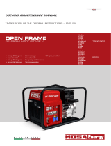
2.4 Control panel
A control panel is located on the generator to enable
checks to be made and the generator to be started up
and stopped. An engine overload protection module [fig.
2, ref. 1] manages generator overload protection, cuts
out the engine in the event of a fault and sends an alarm
signal by means of the warning lights.
-If the green warning light “RUN” [fig. 2, ref. 2] is lit up it
means that the generator is running and that no operat-
ing fault has been detected.
GB

IS
27
mase
-If the red warning light “BATT.” [fig. 2, ref. 3] lights up it
means that the battery charger alternator is faulty.
-If the red warning light “OIL” [fig. 2, ref. 4] lights up it
means that engine oil pressure is too low.
-If the red warning light “ °C “ lights up it means that the
temperature of the cooling liquid or the water in the heat
exchangers is too high.
-If the red warning light “ °C “ lights up it means that the
temperature of the alternator coils is too high.
The control panel also contains:
-a two-pole cut-out switch [fig. 2, ref. 7] that interrupts the
current in the event of an overload or short circuit;
-a cut-out switch [fig. 2, ref.8] to protect the low voltage
electrical circuit from short circuits;
-an overload protection switch [fig. 2, ref.9] to protect the
battery charger alternator;
-a counter [fig. 2, ref.10];
-a generator start or stop button [fig. 2, ref.11].
The control panel can be connected by connector [fig. 2,
ref.12] to the remote control panel [fig. 3, ref. 1 - 5] that
is supplied as an optional extra by mase and which is
installed on the navigation bridge.
There are two different models of remote control panel
and they are illustrated in fig. 3.
The more basic model has a start and stop button [fig. 3,
ref. 3], a green warning light [fig. 3, ref. 2] that indicates
that the generator is on if it is lit up and a red warning light
[fig. 3, ref. 4] that comes on to show that the generator
has switched off because of an operating fault.
The second version of the remote control panel [fig. 3,
ref. 5] not only has the start and stop button and the
warning lights but also an instrument that shows engine
oil pressure [fig. 3, ref. 7], an instrument that shows
cooling liquid temperature [fig. 3, ref. 6], a volt meter that
shows battery voltage [fig. 3, ref. 8] and a counter [fig. 3,
ref. 9].
When the remote control panel is switched on it is not
possible to start up the generator from the local panel.
Before carrying out maintenance
work on the generator, disconnect the remote con-
trol panel.
3 USING THE GENERATOR
3.1 Preliminary checks
When the generator is first started up or if any mainte-
nance has been carried out, always check first that:
- The oil is at the correct level on the dipstick [fig. 4, ref.
1]: see Table A ‘Recommended Oils’ fig. 4.
- The generator has been firmly bolted down at all
points
- All electrical equipment has been disconnected in
order to prevent the generator from being started up
whilst it is wired up to electrical equipment.
- The water and fuel pipes are connected correctly.
- The generator has been correctly wired and there are
no connections in a poor condition.
- The water valve is open [fig. 5, ref. 2]
- The water circuit from the pump to the valve has been
filled manually if a check valve has been fitted on the sea
water intake (as recommended) [fig. 5, ref. 1].
3.2 Bleeding the air from the supply system
If there are air bubbles inside the supply system they are
caused by engine malfunctions or the inability to reach
the nominal rpm. Air may enter the inside of the supply
circuit via a non-airtight joint (pipes, filters, tank) or if the
fuel inside the tank is at minimum. To eliminate the air
bubbles, first of all eliminate the cause and carry out the
following operations:
1- Loosen the bleed screw on the fuel filter [fig. 5, ref. 2]
(also consult the engine use and maintenance manual).
2- Adjust the AC fuel pump lever manually [fig. 5, ref. 1]
until all the air in the supply system has been released
through the bleed screw.
3- Tighten up the bleed screw [fig. 5, ref. 2] and start up
the engine.
4- Repeat the operations described above if engine
operation is still irregular.
3.3 Start-up
Before starting up the generator, make sure that the
preliminary checks described in paragraph 3.1 have
been carried out.
Press the START button on the control panel [fig. 2, ref.
11] to start up the generator. and release it only after the
generator has started up. Do not keep it pressed for
more than 15 seconds for each attempt and pause at
least 15 seconds between attempts. The warning light s
of the engine protection module will come on for a few
seconds [fig. 2, ref. 1] but if there are no engine or
generator faults only the green RUN warning light [fig. 2,
ref. 2] will remain on to show that the generator has
started up and operation is regular.
GB

IS
28
mase
This is triggered and switches off the generator to protect
the alternator from thermal overload If it is tripped,
warning light “°C” [fig. 2, ref. 5] comes on.
The generator can only be switched on again after a few
minutes when the temperature of the alternator windings
has returned to normal. The generator must not be
started up until the cause of the fault has been identified
and eliminated.
If one of the above safety devices
is triggered the cause must be ascertained and
eliminated and then button “STOP” must be pressed
to reset the control panel (otherwise the signal will
remain stored) to prevent the engine from starting
up.
4.4 Short circuit and overload protection
The generator is protected from short circuits and elec-
trical overloads. A twin-pole cut-out switch [fig. 2, ref. 7]
interrupts the power supply when a short circuit occurs
or when the power supplied exceeds the nominal value.
Before restoring the power supply by pushing up the
switch lever, disconnect the electrical equipment.
4.5 Short circuit and overload protection for the
battery charger DC alternator.
If the battery charger DC alternator is overloaded or has
a short circuit a one-pole cut-out switch [fig. 2, ref. 9]
interrupts the power supply to the 12 volt battery charger.
Before restoring the power supply by pressing the button
on the cut-out switch [fig. 2, ref. 9] have the generator’s
starter battery checked by a qualified technician.
4.6 Short circuit protection for the low voltage elec-
tric system.
If the low voltage circuit short circuits a cut-out switch
[fig. 2, ref. 8] will interrupt the circuit and stop the
generator. In the case the warning lights of the engine
protection module will all go out and it will not be possible
to start up the system again.
Before restoring the power supply by pressing the button
located on the cut-out switch [fig. 2, ref. 8] have a
qualified technician eliminate the cause of the short
circuit.
5 MAINTENANCE
Before carrying out any work on
the generator switch off the engine and leave it to
cool. Any work must be carried out only by author-
ised personnel.
GB
Repeated unsuccessful attempts
to start up the generator can cause an excessive
amount of water to accumulate in the discharge
system and this may seriously damage the engine.
If it is difficult to start up the engine , the attempts
should not be continued too long without first clos-
ing the sea water intake valve.
3.4 Stop
Press the “STOP” button on the control panel to stop the
generator [fig. 2, ref. 11].
Before stopping the generator
run it for a few minutes without connecting it to the
power supply so that the engine and alternator can
cool off.
4 SAFETY DEVICES
The IS series generator has a series of safety devices
that protect it from incorrect use and malfunctions.
When the generator stops because a safety device has
been triggered the light indicating the fault that has
arisen will light up on the engine overload protection
module [fig. 2, ref. 1] of the control panel.
4.1 Low oil pressure safety device
This is triggered when engine oil pressure is insufficient.
If it is triggered the “OIL” warning light comes on [fig. 2,
ref. 4].
It is normally sufficient to replace the amount of oil that
is missing in order to start up the unit again.
The low oil pressure safety device
does not show the level of oil in the sump. The oil
level must therefore be checked everyday.
For the engine to work correctly,
it may be tilted more than 30° for less than 3 minutes
and 25° for unlimited periods, both on the longitudi-
nal and transversal axes. If the engine operates at
greater tilts, there is danger of insufficient lubrica-
tion or the air filter may take in lubricating oil.
4.2 High water temperature safety device
This is triggered and switches off the generator when the
temperature of the engine’s refrigerating fluid is too high
or if the sea water circuit fails.
If it is tripped, warning light “°C” [fig. 2, ref. 5] comes on.
The generator must not be started up until the cause of
the fault has been identified and eliminated.
4.3 Alternator thermal overload protection

IS
29
mase
Before approaching the genera-
tor disconnect one of the poles of the start battery so
that it cannot be accidentally started up.
5.1 Routine maintenance of the engine
The regular tasks that must be carried out on the engine
are shown on the table.
For more detailed information, consult the manual sup-
plied by the engine manufacturer that accompanies
each generator .
Use the dipstick to check the oil
level [fig. 4, ref. 1]. The level must always be between
the MAX. and MIN notches on the dipstick [fig. 4, ref.
2] .
5.2 Changing engine oil and oil filter
The engine sump has the following capacity:
IS 11 - 13.5 L. 4.7
IS 15 - 18.5 L. 5.8
IS 21 - 23 L. 10.2
Oil must be poured in and topped up through the hole [fig.
7, ref. 1 - 2].
To change the oil the engine sump, remove the dipstick
[fig. 4, ref. 2], remove the screw that serves as a cap and
use the extraction pump [fig. 7, ref. 3].
Drain the oil whilst it is still warm enough to allow it to
drain off easily.
See Table “A”, fig. 4 for information on recommended
oils.
The engine oil must be changed
for the first time after 50 hours of generator opera-
tion; the second and subsequent oil changes can
take place every 200 hours.
For more detailed information on
engine lubrication consult the engine use and main-
tenance manual that accompanies the generator.
Do not dump used oil as it is a
polluting product.
Deliver the lubricating oil to the collection centres
that are responsible for the disposal of oil.
Do not allow the engine oil to
come into contact with the skin. During mainte-
nance operations use protective gauntlets and gog-
gles.
If the lubricating oil comes into contact with the eyes
or skin, wash the affected part immediately and
thoroughly with soap and water.
To replace the engine oil filter [fig. 7, ref. 4], unscrew it
from its support using the tools that are normally com-
mercially available. Refit the new filter and take care to
lubricate the ring seal. The first filter must be changed
after 50 hours of generator operation and the second
and subsequent ones must be changed every 400
hours.
For further information, see the engine use and mainte-
nance manual.
To ensure engine maintenance
use only manufacturer approved spare parts.
When operations have been com-
pleted, thoroughly clean all the parts of the genera-
tor that are covered in oil and fuel.
5.3 Cleaning the air filter
The IS series generators have a dry air filter that stops
foreign bodies from entering the combustion chamber.
Clean the filter with paraffin once a year to free it of
impurities.
Do not dump the liquids used for
washing the air filter but take them to an approved
collection centre.
5.4 Replacing the fuel filter
In order to ensure that the engine has a long working life,
the fuel filter must be replaced regularly at the intervals
indicated by the engine manufacturer on the table set
out in paragraph 5.12.
To change the fuel filter, follow this procedure:
- close the fuel valve [fig. 6, ref. 3].
- loosen the supporting ringnut completely [fig. 6, ref. 4]
- remove the old cartridge and fit the new one
- to fit again repeat the operations in the reverse order.
After the filter has been replaced, the supply system
must be bled to remove all the air bubbles that have
formed inside (see paragraph 3.2).
Do not allow the fuel to come into
contact with the skin. During maintenance opera-
tions use protective gauntlets and goggles.
If the lubricating oil comes into contact with the eyes
or skin, wash the affected part immediately with
soap and water.
After the fuel has been drained,
carefully clean off all traces of fuel and take the rags
to the appropriate collection centre.
GB

IS
30
mase
5.5 Checking the cooling liquid
The level of cooling liquid in the closed cooling circuit
must be checked regularly. The reference marks for his
check are displayed on the expansion tank [fig. 7, ref. 5].
If the level is insufficient, pour cooling liquid into the
expansion tank but do not go beyond the marked filling
level.
Never open the cap of the expan-
sion tank [fig. 7, ref. 5] and the exchanger [fig. 7, ref.
6] when the engine is hot to avoid the risk of cooling
water escaping.
5.6 Checking the tension of the V-belts.
A V-belt is used to transmit the rotation direction from the
engine shaft pulley to the sea water pump pulley [fig. 8,
ref. 1] .
Excessive belt tension will cause it to wear out more
quickly whilst excessive slackness will cause the pulleys
to rotate idly and will not enable a sufficient quantity of
water to be circulated.
Adjust belt tension in the following manner: loosen the
two adjusting screws [fig. 8, ref. 2] and move the sea
water pump to the outside to increase tension and to the
inside to slacken it. Lock the screws in position and
check belt tension.
The belt has been correctly adjusted if it yields about 5
mm if a thrust of 8 kg is exerted
5 mm [fig. 8 ].
A second belt transmits the rotation from the engine
shaft pulley to the closed circuit liquid pump shaft and the
battery charger DC alternator shaft [fig. 8, ref. 3].
Adjust belt tension in the following manner:
loosen the adjusting screw [fig. 8, ref. 4] and move the
battery charger DC alternator [fig. 8, ref. 5] towards the
outside to increase tension and to the inside to slacken
it.
The belt has been correctly adjusted if it yields about 10
mm if a thrust of 8 kg is exerted
5 mm [fig. 8 ].
To prevent the belt rotating idly,
do not spill oil onto it. Clean the belt with petrol if it
has oil on it.
Keep hands away from the V-belt
or the pulleys when the engine is running.
5.7 Emptying the cooling system
Before carrying out maintenance on the water-air ex-
changer or the cooling system, empty the sea water from
the intake circuit. This operation must be carried out in
the following way:
- shut off the sea intake valve [fig. 5, ref. 2];
- open the discharge valve [fig. 3, ref. 3] so that the water
drains out completely;
- close the discharge valve again.
Open the sea water intake valve
before starting up the generator again.
5.8 Replacing the cooling liquid
Replace the cooling liquid inside the closed cooling
circuit every year.
Connect a piece of 20 - 30 cm rubber tubing [fig. 10, ref.
2] to the discharge valve [fig. 10, ref. 1] at the base of the
engine to enable used cooling liquid to be more easily
collected into the collection receptacle [fig. 10, ref. 3].
Open the valve and completely drain the closed cooling
circuit.
After the circuit has been drained, fill it with new refriger-
ating liquid.
Do not dump the refrigerating
liquid because it is a polluting product.
Deliver the refrigerating liquid to the appropriate
collection centre for disposal.
5.9 Replacing zinc anodes.
To protect the water-air heat exchanger [fig. 9, ref. 3], the
water liquid heat exchanger
[fig. 9, ref. 1- 2] and the discharge collector’s heat
exchanger [fig. 9, ref. 4] from galvanic currents five
sacrificial zinc anodes have been inserted inside. They
must be regularly checked for signs of wear and re-
placed if necessary in order to prevent galvanic currents
irreparably corroding the exchanger.
Check the zinc at least once a month when the unit is
new to check the speed at which it is wearing out and
take the appropriate action.
Change the zinc anodes at least once a year.
5.10 Alternator maintenance
The alternator used for this model is synchronous, self-
excited with electronic voltage control. This alternator
model does not have a brush collector and does not
require any special maintenance. The regular checks
and maintenance are limited to the elimination of traces
of humidity and oxidation that could damage it.
5.11 Battery maintenance
To start up all the generator models an 80 A/h battery is
recommended for ambient temperatures above 0 °C
and an 100 A/h battery is recommended for tempera-
tures below that. Before fitting a new battery, it must be
subjected to a complete recharging cycle.
GB

IS
31
mase
5.13 Table of scheduled maintenance tasks
OPERATION HOURS
Check engine oil level ........................................ 10
Check cooling liquid level.................................. 10
Check for oil leaks.............................................. 20
Check for fuel leaks............................................ 20
Check for liquid leaks ........................................ 20
Adjust V-belt tension........................................ 100
Check battery................................................... 100
Clean fuel filter ................................................ 200
Adjust belt tension .......................................... 200
* Change engine oil ......................................... 200
Check sea water pump impeller ..................... 400
Check engine revolutions ............................... 400
Check wiring. ................................................... 400
Replace fuel filter............................................. 400
* Replace oil filter ............................................ 400
Check injectors................................................ 400
Check injection timing .................................... 400
Adjust play of intake/discharge valve............ 400
Check fuel injection pump ............................. 1000
Check level of electrolyte
in the battery...................................... every month
Clean and deoxidise the metal parts........... yearly
Clean air filter ............................................... yearly
Replace all cooling liquid............................ yearly
Replace zinc anodes ................................... yearly
* Change the oil for the first time after 50 hours of use
and every 400 hours thereafter.
5.14 Fault table
The starter motor works but the engine does not
start.
- Check that there is fuel in the tank (Fill up tank)
- Check that the stop electromagnet is in the attraction
position. (Consult the Assistance Centre)
- Bleed air from the supply circuit. (See paragraph 3.2)
The engine overload protection module does not
start when the START button is pressed
- Check that the overload cut-out switch [fig. 2, ref. 8] has
not been pressed. (To reset, press the red button) [fig. 2,
ref. 8])
- Check the battery cables and terminals and the wiring.
(Reconnect).
- Check the battery. (Recharge or replace )
The generator switches off during operations.
- Check whether a safety device has been triggered and
a warning light has come on (Eliminate the cause and try
to start up again).
- Check for fuel in the tank (Top up).
The engine is producing a lot of exhaust fumes
- Check that the level of oil in the sump is not above the
GB
Check the level of the electrolyte at least one a month
and if necessary top it up with distilled water.
If the generator in not going to be used for a prolonged
period it should be disconnected and stored in a dry
place at a temperature above 10 °C and should be
completely recharged once a month.
If the battery is left completely flat
for long periods it could be permanently damaged.
The battery’s positive clamp should be covered with
Vaseline to protect it from corrosion and oxidation.
For topping up with sulphuric
acid, ready-made solutions must be used.
When topping up the batteries
with water or acid wear protective gauntlets and
goggles to prevent the acid accidentally coming
into contact with the skin.
If the battery liquid accidentally comes into contact
with the skin wash the affected part thoroughly with
soap and water and consult a doctor.
Before recharging the battery
check the level of electrolyte and top it up if neces-
sary with distilled water. This must be done after
recharging has taken place.
5.12 Periods of inactivity
Start up the generator at least once a month.
If the generator is not going to be used for a prolonged
period, proceed as follows:
- Replace the engine oil.
- Replace the oil filter cartridge (see paragraph 5.2).
- Replace the fuel filter cartridge(see paragraph 5.4).
- Remove the injectors, insert 2 cc of engine oil and run
the engine for a few revolutions by manually operating
the pulley of the engine shaft.
Refit the injectors.
- Replace the zinc pads (see paragraph 5.8)
- Draw up the anti-freeze liquid through the sea water
inlet pipe. The anti-freeze protects the exchangers from
low temperatures and lubricates the sea water pump
impeller and the metal parts inside the cooling system.
- Disconnect the starter battery and store in a dry place
(see paragraph 5.10)
- Disconnect the pipe that discharges into the sea from
the engine collector.
- Clean the sea water filter
- Close the sea water intake valve
- Drain the sea water from the exhaust.
- Clean and lubricate the siphon break, if one has been
fitted.

IS
32
mase
MAX. mark (Top up the level).
- Check that the unit is not overloaded.
- Check injector setting. (Consult Assistance Centre)
The engine operates irregularly.
- Check the fuel filters. (Replace )
- Bleed air from the supply circuit. (See paragraph 3.2)
Alternator voltage is too low.
- Correct the voltage on the electronic adjuster
- Check engine rpm (1560 rpm without being connected
to electrical equipment)
- Voltage adjuster does not work (replace).
Starter battery flat.
- Check the level of the electrolyte in the battery. (Top up)
- Check DC alternator operation.
- Check the state of the battery
Any type of operation that is
not included in this manual must be considered to
be strictly prohibited in the interests of your
safety and the safety of other people.
6 SPECIFICATIONS
IS11 IS13.5 IS15 IS18.5 IS21 IS23
ENGINE Y A N M A R
Model 3TNE88 3TNE88 4TNE88 4TNE88 4TNE94 4TNE94
Displacement cc 1642 1642 2190 2190 2776 2776
Alesaggio x corsa mm 88x90 88x90 88x90 88x90 94x100 94x100
RPM g/min. 1500 1800 1500 1800 1500 1800
Power Hp 18.1 21.9 24.1 29 39 46.4
Fuel consumtion g/hp/h 165 165 165 165 155 155
Fuel type diesel
Starter electric 12 volt
Oil capacity l 13.5 13.5 18.5 18.5 23 23
Maximum inclination 30°
ALTERNATORE
Model Syncronous — single phase — self-exited four poles — electr. voltage regul.
Rated power Kw 10.2 12.3 13.9 16.7 18 21
Power factor (cos φ)1
Insulation class H
Frequency Hz 50 60 50 60 50 60
GB

IS
33
mase
References for the wiring diagram (fig. 11)
1 Safety cut-out switch
2 Counter
3 Terminal clamp
4 Rotor
5 Stator
6 Electronic voltage adjuster
7 Battery
8 Starter motor
9 Stop electromagnet
10 Battery charger DC alternator
11 Pressure switch
12 High water temperature switch
13 High cooling liquid temperature switch
14 Al oil pressure sensor
15 Al cooling water temperature sensor
16 Connector
17 Battery charger current cut-out switch
18 Low voltage system cut-out switch
19 Engine overload protection module
20 Remote control panel connection connector
21 Start and stop button
GB
6.1 REFERENCES FOR WIRING DIAGRAMS
References for the wiring diagram (fig. 12)
1 Safety cut-out switch
2 Counter
3 Terminal clamp
4 Rotor
5 Stator
6 Electronic voltage adjuster
7 Battery
8 Starter motor
9 Stop electromagnet
10 Battery charger DC alternator
11 Pressure switch
12 High water temperature switch
13 High cooling liquid temperature switch
14 Al oil pressure sensor
15 Al cooling water temperature sensor
16 Connector
17 Battery charger current cut-out switch
18 Low voltage system cut-out switch
19 Engine overload protection module
20 Remote control panel connection connector
21 Start and stop button
References for the wiring diagram (fig. 13)
1 Safety cut-out switch
2 Counter
3 Terminal clamp
4 Rotor
5 Stator
6 Electronic voltage adjuster
7 Battery
8 Starter motor
9 Stop electromagnet
10 Battery charger DC alternator
11 Pressure switch
12 High water temperature switch
13 High cooling liquid temperature switch
14 Al oil pressure sensor
15 Al cooling water temperature sensor
16 Connector
17 Battery charger current cut-out switch
18 Low voltage system cut-out switch
19 Engine overload protection module
20 Remote control panel connection connector
21 Start and stop button
22 Terminal board
References for the wiring diagram (fig. 14)
1 Safety cut-out switch
2 Counter
3 Terminal clamp
4 Rotor
5 Stator
6 Electronic voltage adjuster
7 Starting relay
8 Battery charger supplying relay
9 Starter
10 Battery
11 Negative pole
12 Electromagnet
13 Battery charger
14 Pressure switch
15 High water temperature switch
16 High cooling liquid temperature switch
17 Connector
18 Battery charger current cut-out switch
19 Low voltage system cut-out switch
20 Remote control panel connection connector
21 Engine overload protection module
22 Start and stop button
23 Terminal board

IS
34
mase
References for the wiring diagram (fig. 15)
gen-set wirh insulated poles
1 Safety cut-out switch
2 Counter
3 Terminal clamp
4 Rotor
5 Stator
6 Electronic voltage adjuster
7 Battery
8 Starter motor
9 Stop electromagnet
10 Battery charger DC alternator
11 Pressure switch
12 High water temperature switch
13 High cooling liquid temperature switch
14 Al oil pressure sensor
15 Al cooling water temperature sensor
16 Connector
17 Relay
18 Low voltage system cut-out switch
19 Engine overload protection module
20 Remote control panel connection connector
21 Start and stop button
22 Ralay
23 Relay
/