Page is loading ...

IS 9000 - 9500
MANUALE DI USO E MANUTENZIONE
USE AND MAINTENANCE MANUAL
MANUEL D’INSTRUCTIONS ET D’ENTRETIEN
GEBRAUCHSANWEISUNG UND WARTUNGSVORSCHRIFTEN
MANUAL USO Y MANTENIMIENTO
GEBRUIKS- EN ONDERHOUDSHANDLEIDING
BRUKS- OG VEDLIKEHOLDSANVISNING
cod. 41313

IS 9000 - 9500
15
mase
FAILURE TO COMPLY WITH THE INSTRUCTIONS
AND SPECIFICATIONS CONTAINED IN THIS
USE AND MAINTENANCE MANUAL WILL
INVALIDATE THE PRODUCT GUARANTEE.
Figures............................................................................. 2
Wiring diagram .............................................................. 5
1 General information ........................................ 16
1.1 Scope of the manual ......................................... 16
1.2 Documentation enclosed .................................. 1 7
1.3 Safety regulations .............................................. 17
2 Description of the generator ........................ 17
2.1 General description ........................................... 17
2.2 Components ....................................................... 17
2.3 Cooling system................................................... 17
2.4 Remote control panel ........................................ 17
3 Use of the generator ....................................... 18
3.1 Preliminary checks ............................................ 1 8
3.1 Removing air from the system ......................... 1 8
2.4 Start-up................................................................ 18
2.5 Stopping .............................................................. 1 8
4 Protection devices .......................................... 18
4.1 Oil pressure low ................................................. 1 9
4.2 Water temperature high .................................... 1 9
4.3 Alternator overheating/overloading ................. 19
5 Maintenance...................................................... 19
5.1 Ordinary maintenance of motor ....................... 1 9
5.2 Changing the oil and oil filter ............................ 2 0
5.3 Cleaning the air filter ......................................... 2 0
5.4 Replacing the fuel filter...................................... 2 0
5.5 Checking coolant ............................................... 2 0
5.6 Checking V-belt tension .................................... 2 0
5.7 Emptying cooling system .................................. 2 0
5.8 Replacing zinc anodes ...................................... 2 1
5.9 Maintenance of the alternator .......................... 2 1
5.10 Maintenance of the battery ............................... 21
5.11 Periods of stoppage .......................................... 2 1
5.12 Table of planned maintenance operations ..... 2 2
5.13 List of possible problems .................................. 22
6 Technical specification .............................. 23
Key to the wiring diagram ........................................ 2 3
CONTENTS
GB

IS 9000 - 9500
16
mase
1 GENERAL INFORMATION
Please read this manual carefully before carrying out any work on the machine.
1.1 Scope of the manual
Thank you for having chosen a mase product.
This manual was prepared by the Manufacturer and is an integral part of the components supplied with the
machine.
This information has been prepared for users and the personnel assigned to perform maintenance on such
equipment.
The manual defines the scope for which the machine was built and contains all the information needed to ensure
safe and correct use.
Strict compliance with these instructions will guarantee the safety of both operators and machine, and will ensure
economic operation and extended machine service life.
In order to facilitate consultation, this manual has been divided into sections which identify the main concepts.
Consult the table of contents for a quick guide to the various subjects.
The most important parts of the text are indicated in bold and are preceded by the symbols illustrated and
described below:
This indicates that operators must be very careful to avoid serious consequences which might lead to the death
of personnel or create possible health hazards.
A situation that might occur during the useful life of the product, system or plant which is considered at risk in terms
of injury to persons or damage to property and the environment or economic losses.
This indicates that careful attention is needed to avoid serious consequences that might damage material goods
such as resources or the product.
Particularly important instructions.
The drawings are supplied for the sake of examples. Even if your machine differs greatly from the illustrations
included in this manual, machine safety and information are still guaranteed.
Since the manufacturer is constantly developing and updating the product, changes may be made without prior
notice.
INFORMATION
DANGER
WARNING
CAUTION
GB

IS 9000 - 9500
17
mase
1.2 Documentation enclosed
The following documents form an integral part of this
manual:
- EEC Declaration of Conformity;
- Motor use and maintenance manual;
- Installation manual;
- Service Booklet;
- Guarantee certificate;
- Guarantee card.
1.3 Safety regulations
- Please read all the information in this manual and in the
installation manual carefully; this is essential for cor-
rect installation and use of the group and to enable you
to intervene quickly in case of need.
- Do not allow unauthorised or untrained persons to use
the group.
- Do not allow children or animals to approach the group
when in operation.
- Do not work on the generator or on the remote control
panel with wet hands, as the generator is a potential
source of electricity if incorrectly used.
- Any controls carried out on the generator group must
be carried out with the motor turned off; controls that
require the group to be in operation must only be
carried out by specialised personnel.
- Do not breathe the exhaust fumes produced by the
machine, as they might damage your health.
In case of any leakage of oil or fuel, clean immedi-
ately to avoid any risk of fire.
In case of fire, use fire extinguishers to extinguish;
never use water.
2 DESCRIPTION OF THE GENERATOR
2.1 General description
The IS 9000-9500 generator group has been designed
to be installed with ease aboard boats.
The soundproofing structure, which uses insulated pan-
els in marine aluminium, allows easy access to the motor
and alternator for maintenance and control operations,
and at the same time gives a high level of sound
reduction.
The 4-stroke, indirect injection Diesel engine, built by
Yanmar, is extremely reliable and robust. The alterna-
tor, which is a synchronous one, is equipped with an
automatic voltage regulator (AVR) that guarantees sta-
bility to +/- 5% of the rated value. The alternator’s
excellent pick-up makes the generator group particu-
larly suited to supply electric motors such as those fitted
in air conditioning and desalination devices, compres-
sors, etc.
The group is equipped with a remote control panel,
complete with connection cable, to be fitted on the
command deck. A microprocessor is in charge of start-
up, stoppage and control of protection devices.
2.2 Generator components
The generator is made up of the following components:
- soundproofing structure [fig. 1, ref. 1];
- motor group [fig. 1, ref. 2];
- alternator group [fig. 1, ref. 3];
- water - water heat exchange group [fig. 1, ref. 4];
- air - water heat exchange group [fig. 1, ref. 5];
- electrical connection panel [fig. 1, ref. 6];
2.3 Cooling system
The generator group motor is cooled by a closed circuit
system containing a heat exchanger that uses sea
water. The heat exchanger, in cupronickel, has been
specially designed by mase for use in a salt water
environment.
When the group is installed a system for intake of the
cooling water is provided (a direct inlet system is recom-
mended), along with the drainage system for the mixture
of used water and exhaust fumes.
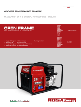
2.4 Remote control panel
Extremely small in size (3.4 x 4.9 in), this is equipped
with a 11 yd. long screened connection cable. Manufac-
tured using state-of-the-art technology, it incorporates a
microprocessor and SMD (miniaturised) components.
The shockproof polyester keyboard, with protection
level IP54 contains an electronic hour counter [fig. 2, ref.
1], the ON / START / OFF commands [fig. 2, ref. 2-4],
function indicators [fig. 2, ref. 5-6], and alarm indicators
[fig. 2, ref. 7-9] for low oil pressure, motor overheating
and alternator overload (see Chapter 4).
The control panel is made up of [fig. 2];
1 - Hour counter
2 - OFF button
3 - START button
4 - ON button
5 - Panel ON indicator (green)
6 - Generator output indicator (green)
7 - Oil pressure indicator (red)
8 - Engine temperature indicator (red)
9 - Alternator temperature indicator (red)
GB
DANGER
DANGER

IS 9000 - 9500
18
mase
3 USE OF THE GENERATOR
3.1 Preliminary checks
When first starting up the group, or after performing any
type of maintenance operation, it is good practice to
ensure:
- That the oil level is correct, using the dipstick provided
[fig. 3, ref. 1]. See the list of recommended oil types on
page 2.
- That all the group’s anchor points are properly locked.
- That all electronic users have been disconnected, to
avoid starting up the group under load.
- That the water and fuel lines are properly connected.
- That all electrical connections have been correctly
carried out, and that none of the connectors are in a
poor state of repair.
- That the water tap [fig. 4, ref. 2] is open.
- That the section of the water circuit leading from the
pump to the valve has been filled manually if there is
a non-return valve on the outboard water intake (as
recommended) [fig. 4, ref. 1].
3.2 Removing air from the system
The presence of air bubbles in the supply system is due
to incorrect operation of the motor or its inability to reach
the rated number of revs. Air can also penetrate into the
system through a joint that has not been properly sealed
(pipes, filters, tank) or when the fuel in the tank is at the
minimum level. To eliminate the air bubbles in the supply
circuit you must first of all remove the cause of the
infiltration and carry out the following operations:
1 - Loosen the bleeder screws on the fuel filter and on
the injection pump (see motor use and maintenance
manual).
2 - Manually adjust the AC fuel pump lever [fig. 5, ref. 3]
until all the air in the supply system has been expelled
through the bleeder screws.
3 - Tighten the bleeder screws again and start the motor.
4 - Repeat the above operations if the motor is still not
operating properly.
3.3 Start-up
Before starting the group, ensure that the preliminary
checks listed above under paragraph 3.1 have been
carried out.
Proceed to start up by pressing the “ON” button on the
control panel [fig. 2, ref. 4]. All the indicator lights will light
up in a self-test for approximately 5 seconds. After this
the panel on indicator [fig. 2, ref. 5] will remain lighted,
along with the “GLOW PLUG” indicator, signalling the
start of operations for pre-heating of the glow plugs,
which last about 10 seconds.
The group cannot be started during pre-heating of
the glow plugs.
After this, start the group by pressing the “START”
button [fig. 2, ref. 3], which must be held down and only
released when the motor has started, taking care not to
hold the button down for more than 10 seconds at a time.
If the group is operating correctly this will be indicated by
light-up of the generator on indicator [fig. 2, ref. 6]. When
the above operations are performed, the group protec-
tion devices are automatically activated (see Chapter 4).
Repeated unsuccessful attempts to start the group
may cause an excessive build-up of water in the
drainage system, which may have a serious nega-
tive effect on the motor.
Should there be any difficulty in starting the motor
it is essential that the tap on the outboard water
intake be closed before making repeated and lengthy
attempts to start the motor.
3.4 Stopping the group
The group is stopped by pressing the “OFF” button on
the control panel [fig. 2, ref. 2].
Before stopping the generator group it is recom-
mended that you operate it for a few minutes without
taking off any power, so that the motor and the
alternator have time to cool down.
4 PROTECTION DEVICES
IS 9000 - 9500 is fitted with a series of protection devices
to safeguard against incorrect use or problems during
operation.
When the group stops because an alarm has been
triggered, details of the running hours will be displayed
on the control panel, along with a code indicating the
reason for stoppage of the generator group.
The following table contains a list of these codes and
their meanings:
TABLE OF ALARM CODES
CODE REASON FOR ALARM
E - 80 No power to genset
E - 81 Oil pressure low
E - 82 Motor temperature high
E - 83 Alternator temperature high
E - 85 Generator set overloaded
E - 87 After 30 s. from start-up, the genset
has not reached 80% of rated voltage
batt Battery voltage low
GB
INFORMATION
CAUTION
CAUTION

IS 9000 - 9500
19
mase
Code E-80 This code indicates that the group has
stopped due to a complete lack of voltage = 0 V. Display
of this code means that:
- the control panel is not able to read the voltage in the
alternator due to a break in an electrical connection;
- the alternator is damaged.
Code E-81 This code indicates that the group has
stopped because the pressure in the motor lubrication
system is insufficient.
Code E-82 This code indicates that the group has
stopped because the motor is too hot.
Code E-83 This code indicates that the group has
stopped because the alternator is too hot.
Code E-85 This code indicates that the group has
stopped because the voltage has dropped to under 70%
of the rated value for over 15 seconds.
Code E-87This code indicates that the group has stopped
because, 30’ after start-up, the voltage in the generator
group has not reached 80% of the rated voltage. This
may be because the engine revs are too low or because
the alternator is broken.
Code batt. This code indicates that the battery voltage
is too low. When this code appears the generator group
is not stopped.
4.1 Oil pressure low
This intervenes to shut down the group when the oil
pressure in the motor is insufficient; intervention is
signalled by light-up of the indicator [fig. 2, ref. 7] and
display of code E-81 on the control panel display unit.
Generally speaking it is sufficient to top up the oil level in
order to restart the group.
The low oil level protection device should not be
used as a general indication of the oil level. It is
therefore essential that the oil level be checked
daily.
The motor operates correctly provided it is not made
to operate at a maximum inclination of 30° for peri-
ods of under 3 minutes, or 25° without a specified
time limit, on either the longitudinal or the transver-
sal axis. If the motor has to operate at a higher
inclination there is a risk that lubrication will be
insufficient or that oil will be sucked into the air filter.
4.2 Water temperature high protection
This intervenes to shut down the generator group when
the temperature of the motor is too high.
Intervention of this protection is signalled by light-up of
the indicator [fig. 2, ref. 8] and display of the code E-82
on the control panel display unit.
The group should only be restarted after the cause of the
alarm has been identified and removed.
4.3 Alternator overheating/overloading protection
This intervenes to shut down the generator group when
the alternator overheats or overloads.
Intervention of this protection is signalled by light-up of
the indicator [fig. 2, ref. 9] and display of the relative code
on the control panel display unit. The group can be
restarted after a few minutes, when the temperature of
the alternator coils returns to a normal level. However it
is recommended that an attempt be made to identify and
remedy the causes of the problem.
If one of the protection devices indicated above
intervenes, after finding and removing the cause of
the alarm, it is necessary to press the “OFF” button
to reset the control panel (otherwise the alarm will
remain stored in the memory).
If one of the fuses [fig. 6, ref. 1] burns out, another
protection that does not form part of this group will
intervene.
5 MAINTENANCE
Any maintenance operation on the generator group
must be carried out with the motor turned off, and
after allowing sufficient time for it to cool down.
These operations must only be carried out by au-
thorised personnel.
Before working on the generator group, disconnect
one pole of the starter battery, to prevent any acci-
dental start-up of the group itself.
5.1 Ordinary maintenance of motor
The periodic maintenance operations to be carried out
on the motor are listed in the table.
For further details, please consult the manual supplied
by the manufacturer of the motor itself, which provided
with each group.
GB
WARNING
CAUTION
INFORMATION
WARNING
DANGER
DANGER

IS 9000 - 9500
20
mase
- remove the old cartridge and replace it with a new one;
- to reassemble, repeat the above operations in reverse
order.
When the fuel filter cartridge has been replaced it is
necessary to bleed the supply system to remove all the
air bubbles that may have formed in it (see paragraph
3.2).
5.5 Checking the coolant
The level of the coolant liquid inside the closed cooling
circuit must be checked periodically. The reference
marks that are used to check the level are printed on the
expansion tank. Should the level be too low, insert more
coolant into the expansion tank, taking care that the level
does not exceed the maximum level mark.
Never open the plug closing the expansion tank [fig.
7, ref. 1] and the heat exchanger [fig. 7, ref. 2] when
the motor is hot, as this might result in a dangerous
outflow of coolant.
5.6 Checking V-belt tension
A V-belt is used to transmit rotation from the engine shaft
pulley to that of the coolant pump and the sea water
pump.
If the tension in this belt is too high this will result in
excessive wear, while if the tension is too low the pulley
will idle and there will not be a sufficient circulation of
water and coolant.
Adjust the belt tension as follows:
loosen the regulation screw [fig. 8, ref. 1] and move the
sea water pump outwards to increase the tension, or
inwards to decrease it.
To prevent the belt from slipping, do not allow it to
become oily. Clean the belt with petroleum if it is
found to be oily when checked.
The belt tension is correct when it gives by approxi-
mately 0.4 in under a thrust of 11 lb. [fig. 8, ref. 2].
Always keep your hands well away from the V-belt
and pulleys when the motor is working.
5.7 Emptying cooling system
To carry out maintenance operations on the air-water
heat exchanger or on the cooling system, the sea water
intake system must be emptied. This is done as follows:
- close the sea water inlet tap [fig. 4, ref. 2];
- open the special drainage tap [fig. 4, ref. 3] and allow
all the water to drain out;
GB
WARNING
WARNING
DANGER
Check the oil level using the dipstick provided [fig.
3, ref. 1 ]. The level must always be between the MAX
and MIN level indicators on the dipstick itself.
5.2 Changing the motor oil
The capacity of the motor oil sump is 4 US qt. Oil is
topped up and replaced through the hole [fig. 5, ref. 4].
To replace the oil in the motor sump, first remove the
dipstick [fig. 3, ref. 2], then operate the extractor pump
provided [fig. 5, ref. 8], after having removed the screw
that acts as a plug [fig. 5, ref. 5].
It is recommended that you change the oil when it is still
sufficiently warm, so that it flows better.
For the recommended oil types, see the table "A", pag.
2.
The motor oil should be changed for the first time
after 50 working hours; the second and subsequent
oil changes are only necessary every 150 working
hours.
For more detailed information on lubrication of the
motor, please consult the motor use and mainte-
nance manual enclosed with the generator group.
Do not discard used oil, as it is a source of pollution.
Used oil should always be handed over to the spe-
cialised Collection Centres responsible for its dis-
posal.
To replace the oil filter cartridge, unscrew it from its
support using appropriate commercially available tools.
When replacing the new cartridge, ensure that the
rubber seal ring is lubricated.
5.3 Cleaning the air filter
IS 9000-9500 is fitted with a net air filter that prevents
foreign bodies from entering the combustion chamber.
To maintain this it is sufficient to clean the filter element
once a year to remove the impurities that have collected
in it.
5.4 Replacing the fuel filter
To guarantee long life and correct operation of the motor
it is extremely important that the fuel filter cartridge be
replaced at regular intervals, in accordance with the
times indicated by the manufacturer and set down in the
table in paragraph 5.11.
This operation is done by proceeding as follows:
- close the fuel tap [fig. 5, ref. 6];
- completely unscrew the support ring nut [fig. 5, ref. 7];
INFORMATION
INFORMATION
CAUTION
DANGER

IS 9000 - 9500
21
mase
- close the drainage tap.
Remember to open the sea water inlet tap again
before restarting the generator group.
5.8 Replacing zinc anodes
Two zinc anodes have been inserted to protect the
water-air heat exchanger from galvanic currents. They
must be checked at regular intervals for wear, and
replaced if necessary, to prevent irreparable corrosion
of the heat exchanger by galvanic currents. It is recom-
mended that these zinc anodes be checked at least once
a month when the group is new, to give a general idea of
the speed of wear, after which the control intervals can
be adjusted accordingly. In any case it is advisable to
replace the zinc anodes at least once a year.
5.9 Maintenance of the alternator
The alternator used on this model of generator is a
synchronous, self-excited on, with electronic voltage
regulation. Periodic controls and maintenance opera-
tions relate to: the brushes, the commutator, and the
Viton bush inside the bearing housing.
- Brushes: check for wear and breakage every 500
working hours. The brushes can be accessed by
removing the hood on the alternator side of the casing
[fig. 1, ref. 3] and the plastic air feeder [fig. 9, ref. 1] fixed
to the cover on the bearing side of the alternator.
Disconnect the red and black wires connected to the
brush holder [fig. 9, ref. 2], and remove the two screws
fixing the brush holder to the cover.
If the brushes are found to be broken or worn, replace
them.
- Commutator: check the commutator before starting
the generator group after a long period of inactivity. This
is necessary to check the state of wear and to eliminate
any oxidation that may have formed, which would pre-
vent current from passing through the brushes. Any
oxide on the commutator can be eliminated by sanding
lightly with very fine sandpaper. If the commutator
shows deep grooves created by the rubbing of the
brushes, these must be eliminated using a lathe.
The commutator is accessed following indications given
above for the brushes.
- Viton bush: this must be replaced every 1000 working
hours, or every two years. The Viton bush, which is
positioned inside the bearing housing [fig. 9, ref. 3], can
be accessed after removing the cover from the alterna-
tor [fig. 9, ref. 4].
The operations described above must only be per-
formed by specialised personnel, or by technicians
from one of the MASE service centres.
Pay particular attention to the way the alternator
cover is replaced, ensuring that the four tie rod nuts
are evenly tightened.
5.10 Maintenance of the battery
To start up the IS 9000-9500 generator group it is
recommended that you use a 55 A/h battery when the
surrounding temperature is 32°F or over, and a 70 A/h
battery when the surrounding temperature is lower.
Before fitting a new battery it is important that the battery
itself be fully recharged.
Check the level of the electrolyte in the battery at least
once a month, and top up with distilled water if neces-
sary.
If the group is not used for a long time it is recommended
that you disconnect the battery and store it in a dry place
at a temperature of over 50°F, recharging it once a
month.
If the battery is left completely uncharged for long
periods there is a risk that it will be irreparably
damaged.
Take care to protect the positive pole of the battery with
vaseline grease, to prevent corrosion and the formation
of oxide.
5.11 Periods of stoppage
If the group is to be stopped for a long period, it is
necessary to proceed as follows:
- Replace the oil in the sump
- Replace the oil filter
- Replace the fuel filter
- Replace the zinc pads (see paragraph 5.8)
- At a temperature of below or close to 32°F, draw in
some antifreeze through the sea water inlet, to protect
the heat exchangers from low temperatures and lubri-
cate the sea water pump rotor.
- Lubricate the water pump rotor
- Disconnect the starter battery and store it in a dry place
(see paragraph 5.10)
- Clean the sea water filter
- Close the sea water inlet tap
- Empty the sea water out of the silencer
- Clean and lubricate the siphon break valve.
GB
CAUTION
CAUTION
WARNING
INFORMATION

IS 9000 - 9500
22
mase
5.12 Table of planned maintenance operations
OPERATION HOURS
Check oil level 10
Check coolant level 10
Adjust V-belt tension 100
Check battery charge 100
Change oil 150
Replace fuel filter 300
Replace oil filter 300
Clean injectors 300
Adjust play in intake/outlet valve 300
Check alternator brushes 500
Calibrate injectors 500
Check alternator commutator 1000
Replace Viton bush 1000
Check electrolyte level in battery monthly
Clean air filter yearly
Completely replace coolant yearly
Replace zinc anodes yearly
5.13 List of possible problems
The starter is working , but the motor will not start.
- Check that there is fuel in the tank. (If not, fill)
- Check whether the stop electromagnet is pulling.
(Contact Service Centre)
- Bleed the supply circuit to remove any air. (see para-
graph 3.2)
The control panel does not light up when the ON
button is pressed.
- Check that the fuses protecting the panel have not
blown. (Replace if necessary)
- Check the connector cable and terminals. (Reconnect)
- Check that the battery is working properly. (Recharge
or replace if necessary)
The group shuts down when in operation.
- Check whether an indicator has lighted to show that an
alarm has been triggered. (If so, remove the cause and
restart)
- Check that there is fuel in the tank. (Fill if necessary)
The motor produces very smoky exhaust
- Check that the oil level in the sump does not exceed the
MAX level indicator. (Adjust the level if necessary)
- Check that the group is not overloaded.
- Check calibration of the injectors. (Contact Service
Centre)
The motor operates irregularly.
- Check the fuel filters. (Replace if necessary)
- Bleed the supply circuit to remove any air bubbles that
may have accumulated. (see paragraph 3.2)
The voltage in the alternator is too low.
- Correct the voltage level by adjusting the electronic
AVR regulator.
- Check the number of revs. (3120 rpm when unloaded)
- The voltage regulator is faulty. (Replace)
The starter battery is low.
- Check the level of the electrolyte in the battery. (Top up
if necessary)
- Check that the recharge device is operating properly.
(Replace if necessary)
- Check that the battery is not damaged.
GB

IS 9000 - 9500
23
mase
Key to the wiring diagram (page 5)
1 Remote control panel
2 Stator
3 Rotor
4 Alternator thermostat
5 Battery charger regulator (B.C.)
6 Stop solenoid valve
7 Starter motor
8 Pre-heating glow plugs
9 Fuses
10 Battery
11 Relay card
12 Oil pressure gauge
13 Motor and water thermostats
14 Automatic voltage regulator (A.V.R.)
15 Power terminals
GB
6 TECHNICAL CHARACTERISTICS
Displacement in
3
Bore x stroke in
Fuel consumption g/Hp/h
Fuel type
Starter system
Oil capacity US qt
Maximum inclination
Continuous power W
Power factor (cos φ)
Insulation class
Frequency Hz
3-cylinder explosion engine — 4-stroke
diesel — water cooled
Model
40.2
3000 3600
26 x 25.3
13
15
Electric, 12 V
30°
4.0
Diesel
180
185
Revs r.p.m.
Power Hp
Model
7600
8500
1
F
50 60
Syncronous — single phase — self-excited
two poles — A.V.R.
MOTOR
Yanmar 3TN66
ALTERNATOR
IS 9000 IS 9500

IS 9000 - 9500
70
mase
Rif. Cod. Qty Descrizione Description
1) 20531 1 Scheda relay Relay board
2) 30448 1 Fusibile 1 A 5x20 Fuse 1 A 5x20
3) 90614 1 Coperchio fusibile Fuse cover
4) 31678 4 Relay Relay
5) 31316 1 Portafusibili Fuse holder
6) 30921 1 Fusibile lamellare 30 A Fuse 30 A
7) 31002 3 Fusibile lamellare 20 A Fuse 20 A
8) 10537 2 Supporto Support
9) 30701 1 Morsettiera di potenza Main terminal board
10) 10566 1 Passacavo Grommet
11) 32005 1 Fusibile lamellare 3 A Fuse 3 A
12) 10844 4 Colonnetta Spacer
13) 07297 1 Pannello sottocruscotto Box
14) 71013 1 Kit insonorizzazione Soundproofing kit
15) 92774 1 Testata lato alternatore Sound shield alternator side
16) 70119 30 cm x 2 Guarnizione Gasket
17) 20506 1 Gomito Union
18) 11157 4 Portagomma Adapter
19) 10793 3 Fascetta Clamp
20) 60908 1 Scambiatore di calore acqua/aria Water/Air intercooler
21) 92798 2 Zinco Zinc anode
22) 80159 2 Zinco completo di tappo Zinc anode with plug
23) 71059 1 Vaso d'espansione Sub-tank
24) 08324 1 Staffa Bracket
25) 92797 1 Tappo scambiatore Heat exchanger cap
26) 08268 1 Scambiatore di calore acqua/acqua Water/water heat exchanger
27) 71056 100 cm Tubo acqua di mare Sea water pipe
28) 71062 20 cm
2
Elemento filtrante Air filter element
29) 08207 1 Coperchio filtro aria Air filter cover
30) 11164 2 Fascetta Clamp
31) 70969 60 cm x 2 Tubo acqua raffreddamento motore Engine cooling water hose
32) 08205 1 Filtro aria Air filter box
33) 62181 1 Staffa Bracket
34) 92777 1 Sportello superiore Upper sound shield
35) 11155 6 Chiusura portello Fastening
36) 92775 2 Sportello laterale Side sound shield
37) 62155 2 Telaio cassa Frame
38) 70210 20 cm x 8 Guarnizione adesiva Adhesive gasket
39) 92776 1 Testata lato motore Sound shield engine side
40) 61716 2 Staffa supporto motore Engine bracket
41) 62152 1 Staffa sinistra antivibranti Left shock absorber bracket
42) 10566 4 Passacavo Cable guide
43) 08078 2 Staffa Bracket
44) 62151 1 Staffa destra antivibranti Right shock absorber bracket
45) 71043 1 Fondo cassa Lower shield
46) 70748 4 Antivibranti Shock absorber
47) 08085 1 Staffa di fissaggio lato motore Fixing bracket engine side
48) 08086 1 Staffa di fissaggio lato alternatore Fixing bracket alternator side
49) 71014 1 Coperchio cruscotto Cover
50) 31618 10 mt Cavo Cable
51) 92407 1 Circuito stampato Printed circuit
52) 70786 40 cm Guarnizione Gasket
53) 70854 1 Scatola cruscotto Control panel box
54) 10089 2 Rondella Washer
55) 10558 1 Vite forata Hollow screw
56) 10571 1 Raccordo ad occhio Union
57) 10960 2 Fascetta Clamp
58) 10866 1 Portagomma Union
59) 70227 35 cm Tubo scarico scambiatore Pipe
60) 10873 1 Fascetta Clamp
61) 70237 60 cm Tubo sfiato scambiatore Pipe

IS 9000 - 9500
72
mase
Rif. Cod. Qty Descrizione Description
1) 20250 1 Pompa olio Oil drainage pump
2) 08202 1 Staffa Bracket
3) 10873 2 Fascetta Clamp
4) 70198 30 cm Tubo scarico olio Oil drainage pipe
5) 11048 1 Raccordo ad occhio Union
6) 11071 1 Vite forata Hollow screw
7) A10414 1 Rondella Washer
8) 10871 1 Snodo sferico Ball gear
9) 10181 1 Prigioniero Stud
10) 10875 1 Forcella Fork
11) 10157 1 Coppiglia Pin
12) 05160 1 Staffa Bracket
13) 05168 1 Staffa Bracket
14) 11164 2 Fascetta Clamp
15) 70630 30 cm Tubo aria Air pipe
16) 70969 60 cm Tubo acqua motore Engine water pipe
17) 92682 1 Pressostato olio Oil pressure switch
18) 92215 1 Cartuccia filtro olio Oil filter cartridge
19) 05158 1 Staffa Bracket
20) 30889 1 Elettromagnete Fuel solenoid
21) 92214 1 Cartuccia filtro carburante Fuel filter cartridge
22) 05159 1 Supporto filtro carburante Fuel filter support
23) 92640 1 Termostato Temperature switch
24) 62118 1 Collettore di scarico Exhaust mixing elbow
25) 30253 1 Sonda temperatura scarico Exhaust thermostat
26) 10793 3 Fascetta Clamp
27) 71056 30 cm Tubo acqua di mare Sea-water pipe
28) 92683 1 Termostato Thermostat
29) 62119 1 Staffa pompa acqua Water pump bracket
30) 11157 2 Portagomma Adapter
31) 71056 100 cm Tubo acqua di mare Sea-water pipe
32) 20506 1 Gomito Union
33) 20285 1 Pompa acqua di mare Sea-water pump
34) 10061 1 Grano Screw
35) 50278 1 Puleggia IS9000 (50 Hertz) Pulley IS9000 (50 Hertz)
50279 1 Puleggia IS9500 (60 Hertz) Pulley IS9500 (60 Hertz)
36) 71054 1 Cinghia Belt
37) 92799 1 Alberino pompa Pump shaft
38) 92800 1 Chiavetta Key
39) 92801 1 Anello elastico Snap ring
40) 92802 2 Cuscinetto Bearing
41) 92803 1 Distanziale Spacer
42) 92804 1 Anello elastico Snap ring
43) 92805 1 Anello OR OR-ring
44) 92806 1 Corpo pompa Pump web
45) 92807 2 Paraolio Oil seal
46) 92794 1 Girante Impeller
47) 92808 1 Guarnizione Gasket
48) 92809 1 Coperchietto Pump cover
49) 70969 60 cm Tubo acqua motore Engine water pipe

IS 9000 - 9500
73
mase
Rif. Cod. Qty Descrizione Description
1) 03830 1 Ventola Fan
2) 03826 1 Coperchio lato motore Engine side cover
3) 10583 1 Linguetta Key
4) 03833 1 Rotore Rotor
5) 10882 1 Anello Seeger Ring
6) 80158 1 Cuscinetto Bearing
7) 70750 1 Boccola Bushing
8) 61321 1 Fascia statore Stator housing
9) 03832 1 Statore IS9000 (50 Hertz) Stator IS9000 (50 Hertz)
04443 1 Statore IS9500 (60 Hertz) Stator IS9500 (60 Hertz)
10) 31165 1 Regolatore elettronico Electronic voltage regulator
11) 10537 2 Supporto Support
12) 61311 2 Staffa supporto morsettiere Bracket
13) 30549 7 cm Guida Support
14) 30546 1 Terminale morsettiera Terminal holder
15) 30616 2 Morsettiera Terminal board
16) 03827 1 Coperchio lato cuscinetto Bearing side cover
17) 70861 1 Convogliatore Manifold
18) 70769 1 Passacavo Cable guide
19) 80542 1 Regolatore carica batteria Battery charger regulator
20) 30701 1 Morsettiera di potenza Power terminal board
21) 31597 1 Portaspazzole con spazzole Brush holder
22) 10859 4 Tirante Tie rod
23) A10270 8 Vite Screw
/