Original instructions
Protector
®
Echo™ &
Protector
®
Airo™
Filtered Fume Hoods
Models
180 Series – 4', 5', 6' and 8' (Echo)
181 Series – 4', 5', 6' and 8' with side glass (Echo)
182 Series – 4', 5', 6' and 8' with 360 degree visibility (Echo)
183 Series – 4', 5', 6' and 8' Floor-Mount only (Echo)
184 Series – 3' and 4' small height models only (Airo)

Original instructions
Copyright © 2018 Labconco Corporation. The information contained in this manual and the accompanying
products are copyrighted and all rights reserved by Labconco Corporation. Labconco Corporation reserves
the right to make periodic design changes without obligation to notify any person or entity of such change.
Returned or Damaged Goods
Do not return goods without the prior authorization from Labconco. Unauthorized returns will not be
accepted. If your shipment was damaged in transit, you must file a claim directly with the freight carrier.
Labconco Corporation and its dealers are not responsible for shipping damages.
The United States Interstate Commerce Commission rules require that claims be filed with the delivery
carrier within fifteen (15) days of delivery.
Limitation of Liability
The disposal and/or emission of substances used in connection with this equipment may be governed by
various federal, state, or local regulations. All users of this equipment are required to become familiar with
any regulations that apply in the user’s area concerning the dumping of waste materials in or upon water,
land, or air and to comply with such regulations. Labconco Corporation is held harmless with respect to
user’s compliance with such regulations.
Contacting Labconco Corporation
If you have questions that are not addressed in this manual, or if you need technical assistance, contact
Labconco’s Customer Service Department or Labconco’s Product Service Department at 1-800-821-5525
or 1-816-333-8811, between the hours of 7:30 a.m. and 5:30 p.m., Central Standard Time.
Part #9411500, Rev. F
ECO L352
Warranty
Labconco Corporation provides a warranty to the original buyer for the repair or replacement of parts and
reasonable labor as a result of normal and proper use of the equipment with compatible chemicals. Broken
glassware and maintenance items, such as filters, gaskets, light bulbs, finishes and lubrication are not
warranted. Excluded from warranty are products with improper installation, erratic electrical or utility supply,
unauthorized repair and products used with incompatible chemicals.
The warranty for Protector
®
Echo™ & Protector
®
Airo™ Filtered Fume Hoods will expire one year from date
of installation or two years from date of shipment from Labconco, whichever is sooner. Warranty is non-
transferable and only applies to the owner (organization) of record.
Buyer is exclusively responsible for the set-up, installation, verification, decontamination or calibration of
equipment. This limited warranty covers parts and labor, but not transportation and insurance charges. If the
failure is determined to be covered under this warranty, the dealer or Labconco Corporation will authorize
repair or replacement of all defective parts to restore the unit to operation. Repairs may be completed by 3
rd
party service agents approved by Labconco Corporation. Labconco Corporation reserves the rights to limit this
warranty based on a service agent’s travel, working hours, the site’s entry restrictions and unobstructed access
to serviceable components of the product.
Under no circumstances shall Labconco Corporation be liable for indirect, consequential, or special damages
of any kind. This warranty is exclusive and in lieu of all other warranties whether oral, or implied.

Original instructions
TABLE OF CONTENTS
CHAPTER 1: INTRODUCTION 1
Model Number Configurator 2
About This Manual 3
Typographical Conventions 4
Your Next Step 5
CHAPTER 2: PREREQUISITES 6
Location Requirements 7
Support Requirements 7
Filtration Technology Airflow and Power Requirements 7
Electrical Requirements 8
Service Line Requirements 8
Space Requirements 8
Commissioning, Setup and Startup Requirements 8
CHAPTER 3: GETTING STARTED 9
Unpacking Your Fume Hood 10
Removing the Shipping Skid 10
Sash Weight Release 11
Installing the Hood on a Supporting Structure and Work Surface 11
Connecting the Electrical Supply Source to the Protector Hood 13
Connecting the Service Lines to the Protector Hood 15
Sealing the Protector Hood to the Work Surface 16
Setting up the Protector Echo Floor-Mounted Filtered Hood 16
Commissioning the Filtration Technology 17
Re-Configuration Process 27
Troubleshooting Guide for GFH 43
Certifying the Protector Filtered Fume Hood 46
CHAPTER 4: PERFORMANCE FEATURES AND SAFETY
PRECAUTIONS 47
Performance Features 47
Safety Precautions 51

Original instructions
CHAPTER 5: USING THE PROTECTOR FILTERED HOOD 59
Access Cards 59
Starting the Filtered Hood 60
Operating the Vertical-Rising Sash 60
The Modular Neutrodine Filtration 60
Detecting a Breakthrough 61
Communication 63
User Options and Approved Chemicals 64
Working in Your Protector Filtered Fume Hood 64
CHAPTER 6: MAINTAINING THE PROTECTOR
FILTERED HOOD 66
Routine Maintenance Schedule 66
Initial Certification 67
Re-Certification 67
User Alarm Code List 67
Tool List 70
Neutrodine SDS for Disposal 71
Partial Filter Replacement Procedure 73
Reconfiguration Process 87
Light and/or Circuit Board Replacement 88
Fan and/or Circuit Board Replacement 90
Fan Box Replacement 92
Electro (Acid) Sensor Replacement 95
Secure Mode 103
gGuard Checklist and Software Option 104
BACnet Checklist Option 104
CHAPTER 7: ACCESSORIZING THE PROTECTOR
FILTERED HOOD 105
Filters 105
Work Surfaces 106
Base Stands, Accessory Shelves, Seismic Supports, and
Hydraulic Lift Base Stands 107
Storage Cabinets 108
Installing Additional Service Fixtures 108
Installing an Electrical Duplex Outlet 110
Installing Optional Guardian™ Digital Airflow Monitor 111
Sash Stop Kit – Field Installation 111
Distillation Grids – Field Installation 112
Installing Remote Monitoring Software 112
Installing BACnet Gateway Hardware 113
ADA Remote Control 113
Additional User, Maintenance, and Administrator Access Cards 113
Sash Reduction Wing Kits 114
CHAPTER 8: TROUBLESHOOTING 115

Original instructions
APPENDIX A: PROTECTOR FILTERED HOOD
REPLACMENT COMPONENTS 118
Protector Echo Filtered Hood Replacement Parts 118
Neutrodine Filtration Technology Replacement Parts 119
APPENDIX B: PROTECTOR FILTERED HOOD DIMENSIONS 122
APPENDIX C: PROTECTOR FILTERED HOOD
SPECIFICATIONS 125
APPENDIX D: SERIAL NUMBER TAG DESCRIPTION 127
APPENDIX E: gGUARD 133
APPENDIX F: BACnet 148
APPENDIX G: SECURE MODE 151
APPENDIX H: CHEMICAL GUIDE 155
APPENDIX I: REFERENCES 171
APPENDIX J: SETTING UP THE PROTECTOR ECHO
FLOOR-MOUNTED FILTERED HOOD 173
APPENDIX K: SMALL 54.2" HEIGHT AIRO DIMENSIONS 185

Product Service 1-800-522-7658
1
Original instructions
CHAPTER 1
INTRODUCTION
Congratulations on your purchase of a Labconco Protector
®
Echo™ or Protector
®
Airo™ Filtered Fume Hood which is unique as it is built on a traditional fume
hood platform along with Neutrodine
®
Filters that handle solvents, acids, and bases
with one comprehensive filter. From here on in this manual, the Protector Airo
only refers to the shorter height 3' and 4' widths with 54.2" exterior height. It
offers a comfortable workspace for users accustomed to the space and utility of a
standard ducted fume hood, but in the realm of a filtered fume hood. The Protector
Filtered Fume Hood solves the problem of ducting in laboratories that are difficult
to vent because of location. The Protector Filtered Fume Hood combines its
patented (U.S. Patent No. 6,461,233) fully featured, containment-enhancing fume
hood design with Neutrodine (by Erlab) filtration technology to deliver a multi-use
ductless fume hood. The Protector Filtered Fume Hood meets the definition of
SEFA 9 DH3 ductless hoods because of its sensor package, backup filters, and
communication. Building communication is one of the most important aspects of
the Protector Filtered Fume Hood. In the event of loss of airflow, damage of a
primary filter, or if a leak reaches the second set of redundant filters for any
reason, an alarm will sound and the communication system will alert a designated
email address. The designated safety officer could be made aware of the problem
immediately through any internet-enabled smart phone, tablet or computer. Large
laboratories and labs where a single safety manager must handle multiple concerns
will benefit most from this proactive safety system.
The Labconco Protector Filtered Fume Hood has been engineered to provide
maximum visibility in a laboratory, and effectively contain toxic, noxious, or other
harmful materials when properly installed. The Protector Filtered Fume Hood
offers many unique features to enhance safety, performance, and visibility. To
take full advantage of them, please acquaint yourself with this manual and keep it
handy for future reference. If you are unfamiliar with how fume hoods operate,
please review Chapter 4: Performance Features and Safety Precautions before
you begin working in the fume hood. Even if you are an experienced fume hood
user, please review Chapter 5: Using Your Protector Filtered Hood, which
describes your filtered hood’s features so that you can efficiently use the hood.

Chapter 1: Introduction
Product Service 1-800-522-7658
2
Original instructions
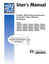
Model Number Configurator
Example:
Product Line Family Configuration Width Depth Airfoil Sash System Electrical Accessories
Fume Hood 1 Filtered Hood 8 BT None 0 4' 4 37.7" BT & FM 1 Eco-Foil 0 Cable 0 115V 0 None 0
BT Sides 1 5' 5 43.7" FM 2 Flush (Special) 4 Chain BT only 1 230V 2 2 Fixtures 1
BT 360 2 6' 6 55.7" FM 3 None-FM only 7 (Special) 2 Fix & 1 GFCI 2
FM None 3 8' 8 (8'-2 GFCI)
Airo/BT Small 4 3' 3
31.7" BT, 0
Height small 3' only
Airo
BT= Benchtop
FM= Floor Mount
2
0
0
1
0
1
4
0
8
Figure 1-1

Chapter 1: Introduction
Product Service 1-800-522-7658
3
Original instructions
About This Manual
This manual is designed to help you learn how to install, use, and maintain your
filtered fume hood. Instructions for installing optional equipment on your hood are
also included.
Chapter 1: Introduction provides a brief overview of the filtered fume hood,
explains the organization of the manual, and defines the typographical conventions
used in the manual.
Chapter 2: Prerequisites explains what you need to do to prepare your site before
you install your filtered fume hood. Electrical and service requirements are
discussed.
Chapter 3: Getting Started contains the information you need to properly unpack,
inspect, install, and certify your filtered fume hood.
Chapter 4: Performance Features and Safety Precautions explains how the
Protector Filtered Hood operates and the appropriate precautions you should take
when using the fume hood.
Chapter 5: Using Your Protector Filtered Hood discusses the basic operation of
your filtered fume hood. Information on how to prepare, use and shut down your
Protector Filtered Hood are included.
Chapter 6: Maintaining Your Protector Filtered Hood explains how to perform
routine maintenance on your filtered fume hood.
Chapter 7: Modifying Your Protector Filtered Hood explains how to modify the
filtered fume hood or add accessories.
Chapter 8: Troubleshooting contains a table of problems you may encounter while
using your filtered fume hood including the probable causes of the problems and
suggested corrective actions.
Appendix A: Protector Filtered Hood Components contains labeled diagrams of all
of the components of the filtered fume hoods.
Appendix B: Protector Filtered Hood Dimensions contains comprehensive
diagrams showing all of the dimensions for the filtered fume hoods.
Appendix C: Protector Filtered Hood Specifications contains the electrical
requirements for the filtered fume hood. Wiring diagrams are also included.
Appendix D: Serial Number Tag Description provides current rating code used on
serial number tag.

Chapter 1: Introduction
Product Service 1-800-522-7658
4
Original instructions
Appendix E: gGuard
Appendix F: BACnet
Appendix G: Secure Mode
Appendix H: Chemical Guide
Appendix I: References lists the various resources available that deal with filtered
fume hoods.
Typographical Conventions
Recognizing the following typographical conventions will help you understand and
use this manual:
Book, chapter, and section titles are shown in italic type (e.g., Chapter 3:
Getting Started).
Steps required to perform a task are presented in a numbered format.
Comments located in the margins provide suggestions, reminders, and
references.
Critical information is presented in boldface type in paragraphs that are
preceded by the exclamation icon. Failure to comply with the information
following an exclamation icon may result in injury to the user or permanent
damage to fume hood.
Les informations critiques sont présentées en gras dans les paragraphes qui
sont précédés par l'icône d'exclamation. Ne pas se conformer aux informations
qui suivent une icône d'exclamation peut résulter à la blessure de l'utilisateur
ou à des dommages irréversibles de la hotte aspirante.
Critical information is presented in boldface type in paragraphs that are
preceded by the wrench icon. These operations should only be performed by a
trained certifier or contractor. Failure to comply with the information
following a wrench icon may result in injury to the user or permanent damage
to your hood.
Les informations critiques sont présentées en gras dans les paragraphes qui
sont précédés par l'icône de clé plate. Ces opérations devraient être seulement
exécutées par un professionnel agrée. L'échec pour se conformer aux
informations qui suivent une icône de clé plate peut résulter à la blessure de
l'utilisateur ou à des dommages irréversibles de la hotte.
Important information is presented in capitalized type in paragraphs that are
preceded by the pointer icon. It is imperative that the information contained in
these paragraphs be thoroughly read and understood by the user.
!

Chapter 1: Introduction
Product Service 1-800-522-7658
5
Original instructions
CAUTION – See Manual. When this symbol is on a fume hood it indicates a
caution that is detailed in this manual.
PRUDENCE – Consulter le Manuel. Quand ce symbole est sur une hotte
aspirante, il indique une prudence qui est détaillée dans ce manuel.
CAUTION – Hot Surface
AVERTIR – Surface Chaude
CAUTION – See Manual. This symbol on the fume hood indicates the
possibility of a pinch hazard.
PRUDENCE – Consulter le Manuel. Ce symbole sur la hotte indique la
possibilité d'un risque de pincement.
Your Next Step
If your Filtered Fume Hood needs to be installed, proceed to Chapter 2:
Prerequisites to ensure your installation site meets all of the requirements. Then,
go to Chapter 3: Getting Started for instructions on how to install your filtered
fume hood and make all of the necessary connections.
If you would like to review how filtered fume hoods operate, go to Chapter 4:
Performance Features and Safety Precautions.
For information on the operational characteristics of your filtered fume hood, go to
Chapter 5: Using Your Protector Filtered Hood.
If your filtered fume hood is installed and you need to perform routine
maintenance on the cabinet, proceed to Chapter 6: Maintaining Your Protector
Filtered Hood.
For information on making modifications to the configuration of your fume hood,
go to Chapter 7: Modifying Your Protector Filtered Hood.
Refer to Chapter 8: Troubleshooting if you are experiencing problems with your
filtered fume hood.
!

Product Service 1-800-522-7658
6
Original instructions
CHAPTER 2
PREREQUISITES
Before you install your filtered fume hood, you need to prepare your site for
installation. Carefully examine the location where you intend to install your
hood. You must be certain that the area is level and of solid construction. In
addition, a dedicated source of electrical power must be located near the
installation site.
Carefully read this chapter to learn the requirements for your installation site:
The location requirements.
The support requirements.
The Filtration Technology airflow and power requirements.
The electrical power requirements.
The service line requirements.
The space requirements.
The commissioning and setup requirements.
Refer to Appendix B: Protector Filtered Hood Dimensions for complete fume
hood dimensions.
Refer to Appendix C: Protector Filtered Hood Specifications for complete filtered
fume hood electrical and environmental conditions, specifications and
requirements.

Chapter 2: Prerequisites
Product Service 1-800-522-7658
7
Original instructions
Location Requirements
The filtered fume hood should be located away from traffic
patterns, doors, windows, fans, ventilation registers, and any
other air-handling device that could disrupt its airflow
patterns. All windows in the room should be closed.
La hotte filtrée devrait être situé loin des modèles de trafic,
portes, fenêtres, ventilateurs, registres de ventilation, et tout
autre dispositif de traitement de l'air qui pourraient perturber
ses modèles de flux d'air. Toutes les fenêtres de la chambre
doivent être fermés.
Support Requirements
ALL Protector Hood installations are usually permanent and
stationary. The supporting structure usually consists of a base
cabinet and chemically-resistant work surface. If needed, the
Protector Hood may be placed on a cart or mobile bench.
Toutes les installations Protecteur de capot sont généralement
permanent et stationnaire. La structure de support est
généralement constitué d'une armoire de base et la surface de
travail résistant aux produits chimiques. Si nécessaire, le Si
nécessaire, le Protecteur du capot peut être placé sur un
chariot ou un banc mobile.
Filtration Technology Airflow and Power
Requirements
Hood
width
Airflow
(CFM)
Makeup
Air (CFM)
Face
Velocity
(fpm)
No. of
modules
Fan
Power
(watts)
Light
Power
(watts)
Total
Power
(watts)
3'
Up to
130
0, limited to
min. volume
required by
local
regulations
and min.
laboratory air
change
requirements.
60-100
1
36
18
54
4'
Up to
260
60-100
2
72
36
108
5'
Up to
390
60-100
3
108
54
162
6'
Up to
520
60-100
4
144
72
216
8'
Up to
650
60-100
5
180
90
270
!
!

Chapter 2: Prerequisites
Product Service 1-800-522-7658
8
Original instructions
Electrical Requirements
The Protector Filtered Hood models feature internal wiring for the fluorescent lights,
fans, and control panel. All internal wiring is terminated with a simple plug in wall
cord. The blower switch and light switch wires are part of the control panel. Refer
to Chapter 3: Getting Started and Appendix C: Protector Filtered Hood
Specifications for the wiring diagram for proper electrical installation.
Les modèles Protector Filtré capot disposent câblage interne pour les lumières,
ventilateurs, et le panneau de contrôle fluorescent. Tout le câblage interne est
terminé avec un simple plug-in cordon de mur. L'interrupteur de la soufflerie et
fils de l'interrupteur de lumière font partie du panneau de contrôle. Reportez-vous
au Chapitre 3: Mise en route et à l'Annexe C: Protector filtrée capot Spécifications
pour le schéma de câblage pour l'installation électrique appropriée.
Service Line Requirements
All service lines to the filtered fume hood should be ¼ inch outside diameter,
copper (brass for natural gas), and equipped with an easily accessible shut-off
valve, should disconnection be required. Recommended operating pressure is 40
PSI, with a maximum allowable pressure of 200 PSI. Consider a pressure
regulator to reduce line pressure to 40 PSI. Please check with local codes for
other requirements.
Space Requirements
The dimensions for the different models are shown in Appendix B: Protector
Filtered Hood Dimensions.
Commissioning, Setup and Startup
Requirements
All commissioning for the Protector Filtered Hood requires installation, setup,
startup and configuration of the Filtration Technology. Certifying the Protector
Filtered Hood should be completed for final commissioning. Refer to Chapter 3:
Getting Started for specifics on completing commissioning.

Product Service 1-800-522-7658
9
Original instructions
CHAPTER 3
GETTING STARTED
Now that the site for your filtered fume hood is properly prepared, you are ready
to unpack, inspect, install, and certify your unit. Read this chapter to learn how
to:
Unpack and move your Protector Hood.
Set up the filtered fume hood with the supporting structure and work surface.
Connect the electrical supply source.
Connect the service lines.
Sealing the Protector Hood to the work surface.
Commissioning the Filtration Technology.
Re-configuration process (first time setup and replacing components).
Arrange certification of your Protector Hood.
Depending upon which model you are installing, you may need common
plumbing and electrical installation tools in addition to 5/16", 3/8", 7/16", and
1/2" wrenches, ratchets, sockets, a nut driver set, a flat-blade screwdriver, a
Phillips screwdriver, and a carpenter level to complete the instructions in the
chapter.
The Protector Hood models weigh between 400 to 835 lbs.
(182-375 kg). The shipping skid allows for lifting with a
mechanical lift truck or floor jack. If you must lift the fume
hood manually, follow safe-lifting guidelines. Normally, the
fume hood can be slid off a hydraulic lift table and be placed
into position on top of the work surface. Do not lift by the
front air foil.
Les modèles Protector capot pèsent entre 400 à 835 livres. (182
à 375 kg). La palette d'expédition permet de levage avec un
chariot élévateur mécanique ou prise de parole. Si vous devez
soulever la hotte manuellement, suivre les directives de
sécurité-levage. Normalement, la hotte peut être glissé sur une
table de levage hydraulique et être placé en position au-dessus
de la surface de travail. Ne pas soulever par la feuille d'air
avant.
!

Chapter 3: Getting Started
Product Service 1-800-522-7658
10
Original instructions
Unpacking Your Fume Hood
Carefully remove the shrink-wrap or carton on your fume hood and inspect it for
damage that may have occurred in transit. All the filtration fans and lights are
packaged in boxes on top of the hood liner and should not be discarded. If
your unit is damaged, notify the delivery carrier immediately and retain the entire
shipment intact for inspection by the carrier.
DO NOT RETURN GOODS WITHOUT THE PRIOR
AUTHORIZATION OF LABCONCO. UNAUTHORIZED
RETURNS WILL NOT BE ACCEPTED.
IF YOUR HOOD WAS DAMAGED IN TRANSIT, YOU MUST
FILE A CLAIM DIRECTLY WITH THE FREIGHT CARRIER.
LABCONCO CORPORATION AND ITS DEALERS ARE NOT
RESPONSIBLE FOR SHIPPING DAMAGES.
Do not discard the shipping skid, fan boxes, harnesses, or packing material for
your filtered fume hood until you have checked all of the components and
installed and tested the unit. Do not remove the filtered fume hood from its
shipping skid until it is ready to be placed into its final location. Move the unit by
placing a flat, low dolly under the shipping skid, or by using a floor jack.
Do not move the hood by tilting it onto a hand truck.
Ne pas déplacer la hotte en le penchant sur un diable.
Removing the Shipping Skid
LEAVE THE FUME HOOD ATTACHED TO ITS SHIPPING
SKID UNTIL IT IS AS CLOSE TO ITS FINAL LOCATION AS
POSSIBLE. MOVE THE HOOD BY USING A SUITABLE
FLOOR JACK, OR BY PLACING A FURNITURE DOLLY
UNDERNEATH THE SKID. DO NOT MOVE THE HOOD BY
TILTING IT ONTO A HAND TRUCK.
After you verify the fume hood components, move your hood to the location
where you want to install it. Should you require disassembly to move the hood,
then follow the instructions in Appendix F. Then, follow the steps listed next to
remove the shipping skid from your unit.
1. Remove the side panels by unscrewing the Phillips screws.
2. Find the hardware (bolts, washers, nuts) that attach the fume hood to
the skid and remove the hardware. Some hardware is on the sides and
some is on the back.
The United
States
Interstate
Commerce
Commission
rules require
that claims
be filed with
the delivery
carrier
within fifteen
(15) days of
delivery.
!

Chapter 3: Getting Started
Product Service 1-800-522-7658
11
Original instructions
Sash Weight Release
To protect the fume hood from damage in shipment, the sash weight has been
secured to the back of the fume hood with screws. Simply remove the screws and
make sure the sash cables or chains are on the pulleys or sprockets before
operation of the sash.
NOTE: THE SASH WEIGHT ITSELF WAS INDIVIDUALLY
MATCHED FOR THIS SPECIFIC HOOD AND SHOULD NOT
BE EXCHANGED ON ANY OTHER UNIT.
Installing the Hood on a Supporting
Structure and Work Surface
The Protector Hood is heavy! Use caution when lifting or
moving the unit.
Le Protecteur Hood est lourd! Soyez prudent lorsque vous
soulever ou déplacer l'appareil.
When installing the Protector Filtered Hood onto a chemically-resistant work surface
or benchtop, ensure that the structure can safely support the combined weight of the
fume hood and any related equipment. The work surface should be at least as wide
as the hood to properly support it. The work surface is aligned flush with the back
of the filtered fume hood for good airflow: this will provide the correct spacing
under the air foil for proper bypass airflow. The lower base cabinets are placed
flush with the front of the work surface as shown in Figure 3-1.
WARNING: It is important to support the rear of the work
surface and filtered fume hood. The cross support provides
support for the bottom of the work surface. Install the cross
support after the base cabinets and work surface are leveled
and before installing the hood.
AVERTISSEMENT : Il est important de soutenir l'arrière de
la surface de travail et filtré hotte. Le support tranversal
soutient le bas de la surface de travail. Installer le support
transversal après que les meubles et la surface de travail soient
nivelés et avant d'installer la hotte.
!
!

Chapter 3: Getting Started
Product Service 1-800-522-7658
12
Original instructions
The following are instructions for mounting a cross support:
1. Level the base cabinets and the work surface. Work surface should be
placed flush with the back of the filtered fume hood as shown in
Figure 3-1.
2. Scribe a line on the wall or back of the base cabinet to locate the
support under the work surface.
3. Mount the support by attaching it to the wall or base cabinet.
4. Place the hood on top of the work surface and cross support.
The work surface should be smooth and durable, such as a chemically-resistant
epoxy resin. The surface should be nonporous and resistant to the acids, solvents,
and chemicals used in conjunction with the Protector Filtered Fume Hood. The
work surface should also contain a dished recessed area for containing primary
spills.
Figure 3-1

Chapter 3: Getting Started
Product Service 1-800-522-7658
13
Original instructions
Connecting the Electrical Supply Source
to the Protector Hood
Prior to connecting any electrical wiring to the fume hood structure, refer to the
hood identification plate for the proper electrical requirements of your specific
model.
WARNING: The building electrical supply system for
Protector Hoods should include overload protection. A switch
or circuit breaker should be in close proximity to the
equipment and within easy reach of the operator. The switch
or circuit breaker is to be marked as the disconnecting device
for the equipment. Consult the current version of NFPA 70
®
,
NEC
®
for proper installation.
AVERTISSEMENT : Le système d’alimentation électrique de la
Hotte Protecteur doit inclure la protection contre la surcharge. Un
commutateur ou disjoncteur doit être tout près de l'équipement et
à portée facile de l'opérateur. Le commutateur ou le disjoncteur
doit être marqué comme l'appareil débranchant pour
l'équipement. Consultez la version actuelle de la norme NFPA 70
®
,
NEC
®
pour une installation correcte.
The identification plate, model number, serial number, and electrical connection
boxes are accessible from the front of the fume hood by removing the front panel.
The Protector Hood is normally wired for 115 Volt, 50/60 Hz, 20 Amp or 230Volt,
50/60 Hz, 10 Amp electrical service. Check the I.D. plate behind the front panel
for voltage verification. The number of circuits varies depending on the model.
All of the electrical connections for the individual duplexes are terminated at the
single point internal junction box for hook-up by a qualified electrician. If needed,
the individual duplexes can be converted for instant attachment to a wall outlet by
a qualified electrician by ordering 115V harness 9582700 or 230V harness
9582701. The main power to the control panel, fans, and lights uses less than 3
amps and a main power cord is included for instant attachment to a wall outlet.
The single point internal junction box is used for the connection of the duplex
outlets. Refer to the wiring diagram for your Protector Hood in Appendix C:
Protector Filtered Hood Specifications.
The fume hood is required to be grounded to the MAINS protective earthing ground
for safe operation. Using a ring terminal sized for a 10-24 machine screw, connect
the MAINS ground conductor to the grounding lug marked with the protective
earthing symbol, . Only MAINS ground conductors should be connected to the
protective earthing ground lug, no other conductors should be connected to this
grounding lug. Using wire nuts, connect the MAINS supply conductors to the fume
hood supply wires. Ensure that the wires are connected as per the appropriate wire
color codes for the input voltage. For 115V Phase (Hot) is black and Neutral is
!

Chapter 3: Getting Started
Product Service 1-800-522-7658
14
Original instructions
white, for 230V Phase1 is brown and Phase2 is blue. Refer to the wiring diagram for
your Protector Hood in Appendix C: Protector Filtered Hood Specifications.
Figure 3-2
Internal Junction
Boxes located on top,
one on each side.

Chapter 3: Getting Started
Product Service 1-800-522-7658
15
Original instructions
All wiring for the filtered fume hood SHOULD be performed
by a licensed electrician and conform to all local codes.
Tout le câblage pour la hotte filtrée doit être effectuée par un
électricien agréé et conformément à tous les codes locaux.
The fluorescent light has been mounted inside the light module located on top of
the filtered hood. To change the fluorescent light bulbs in your filtered hood, you
must first remove the front panel from the hood. Next remove the filters, pre-
filters, and fan modules. Lift fixture up and replace any deflective bulbs. Reverse
order to reassemble.
Connecting the Service Lines to the
Protector Hood
The filtered hoods with service fixtures have been plumbed from the valve to the
hose connector or gooseneck for your installation convenience. Supply tubing
shall be provided by the qualified installer. Tubing can enter the filtered hood
from above, through the back, or through the work surface to make these
connections to the service fixtures.
NOTE: Inspect all fittings for leakage. Tighten the fittings
slightly if needed.
NOTE : Inspecter toutes les installations à la recherche de
fuite. Resserrer les installations légèrement si nécessaires.
CAUTION: Do not use oxygen with any standard service
fixture. Contact Labconco Customer Service for oxygen
fixture information.
PRUDENCE : Ne pas utiliser de l'oxygène avec l'accessoire de
service standard. Contacter le Service Clientèle de Labconco
pour les informations d'accessoire d'oxygène.
Should access to the filtered hood plumbing fixture bodies be required, remove
the service access plate on the hood front corner posts by loosening their
individual screws (see item 11, Figure A-1 in Appendix A). The valve body will
now be fully exposed for any service work that may be necessary. The service
fixtures supplied on your laboratory hood are designed for use with the following
services:
Air
Hot Water
Vacuum
Cold Water
Natural Gas – See caution below
!
!
Page is loading ...
Page is loading ...
Page is loading ...
Page is loading ...
Page is loading ...
Page is loading ...
Page is loading ...
Page is loading ...
Page is loading ...
Page is loading ...
Page is loading ...
Page is loading ...
Page is loading ...
Page is loading ...
Page is loading ...
Page is loading ...
Page is loading ...
Page is loading ...
Page is loading ...
Page is loading ...
Page is loading ...
Page is loading ...
Page is loading ...
Page is loading ...
Page is loading ...
Page is loading ...
Page is loading ...
Page is loading ...
Page is loading ...
Page is loading ...
Page is loading ...
Page is loading ...
Page is loading ...
Page is loading ...
Page is loading ...
Page is loading ...
Page is loading ...
Page is loading ...
Page is loading ...
Page is loading ...
Page is loading ...
Page is loading ...
Page is loading ...
Page is loading ...
Page is loading ...
Page is loading ...
Page is loading ...
Page is loading ...
Page is loading ...
Page is loading ...
Page is loading ...
Page is loading ...
Page is loading ...
Page is loading ...
Page is loading ...
Page is loading ...
Page is loading ...
Page is loading ...
Page is loading ...
Page is loading ...
Page is loading ...
Page is loading ...
Page is loading ...
Page is loading ...
Page is loading ...
Page is loading ...
Page is loading ...
Page is loading ...
Page is loading ...
Page is loading ...
Page is loading ...
Page is loading ...
Page is loading ...
Page is loading ...
Page is loading ...
Page is loading ...
Page is loading ...
Page is loading ...
Page is loading ...
Page is loading ...
Page is loading ...
Page is loading ...
Page is loading ...
Page is loading ...
Page is loading ...
Page is loading ...
Page is loading ...
Page is loading ...
Page is loading ...
Page is loading ...
Page is loading ...
Page is loading ...
Page is loading ...
Page is loading ...
Page is loading ...
Page is loading ...
Page is loading ...
Page is loading ...
Page is loading ...
Page is loading ...
Page is loading ...
Page is loading ...
Page is loading ...
Page is loading ...
Page is loading ...
Page is loading ...
Page is loading ...
Page is loading ...
Page is loading ...
Page is loading ...
Page is loading ...
Page is loading ...
Page is loading ...
Page is loading ...
Page is loading ...
Page is loading ...
Page is loading ...
Page is loading ...
Page is loading ...
Page is loading ...
Page is loading ...
Page is loading ...
Page is loading ...
Page is loading ...
Page is loading ...
Page is loading ...
Page is loading ...
Page is loading ...
Page is loading ...
Page is loading ...
Page is loading ...
Page is loading ...
Page is loading ...
Page is loading ...
Page is loading ...
Page is loading ...
Page is loading ...
Page is loading ...
Page is loading ...
Page is loading ...
Page is loading ...
Page is loading ...
Page is loading ...
Page is loading ...
Page is loading ...
Page is loading ...
Page is loading ...
Page is loading ...
Page is loading ...
Page is loading ...
Page is loading ...
Page is loading ...
Page is loading ...
Page is loading ...
Page is loading ...
Page is loading ...
Page is loading ...
Page is loading ...
Page is loading ...
Page is loading ...
Page is loading ...
Page is loading ...
Page is loading ...
Page is loading ...
Page is loading ...
Page is loading ...
Page is loading ...
Page is loading ...
Page is loading ...
Page is loading ...
Page is loading ...
Page is loading ...
Page is loading ...
/