PASCO OS-8477A Owner's manual

Type
Owner's manual

This manual is also suitable for

Human Eye Model
OS-8477A
Instruction Manual
012-13032A
®
800-772-8700 www.pasco.com
Human Eye Model Table of Contents
Contents
Quick Start . . . . . . . . . . . . . . . . . . . . . . . . . . . . . . . . . . . . . . . . . . . . . . . . . . . . . . . . . . . . 1
Introduction . . . . . . . . . . . . . . . . . . . . . . . . . . . . . . . . . . . . . . . . . . . . . . . . . . . . . . . . . . . 2
Maintenance and Storage . . . . . . . . . . . . . . . . . . . . . . . . . . . . . . . . . . . . . . . . . . . . . . . . 3
Specifications. . . . . . . . . . . . . . . . . . . . . . . . . . . . . . . . . . . . . . . . . . . . . . . . . . . . . . . . . .4
Adjustable Focus Lens. . . . . . . . . . . . . . . . . . . . . . . . . . . . . . . . . . . . . . . . . . . . . . . . . . . 5
Background . . . . . . . . . . . . . . . . . . . . . . . . . . . . . . . . . . . . . . . . . . . . . . . . . . . . . . . . . . .7
Experiment Setup . . . . . . . . . . . . . . . . . . . . . . . . . . . . . . . . . . . . . . . . . . . . . . . . . . . . . 13
Experiment 1: Optics of the Human Eye . . . . . . . . . . . . . . . . . . . . . . . . . . . . . . . . . . . . 15
Experiment 2: Telescope . . . . . . . . . . . . . . . . . . . . . . . . . . . . . . . . . . . . . . . . . . . . . . . . 27
Experiment 3: Refraction, a Detailed Study. . . . . . . . . . . . . . . . . . . . . . . . . . . . . . . . . . 31
Other Suggested Activities. . . . . . . . . . . . . . . . . . . . . . . . . . . . . . . . . . . . . . . . . . . . . . . 35
Teachers’ Notes. . . . . . . . . . . . . . . . . . . . . . . . . . . . . . . . . . . . . . . . . . . . . . . . . . . . . . . 37
Technical Support . . . . . . . . . . . . . . . . . . . . . . . . . . . . . . . . . . . . . . . . . . . . . . . . . . . . . 40
Human Eye Model
OS-8477A
®
1
Quick Start
1. Put the retina screen in the NORMAL slot
and the +120 mm lens in the SEPTUM slot.
2. Fill the model with water.
3. Aim the eye at a bright, distant object such
as a window or lamp across the room.
An image is formed on the retina screen.
Eye Model
Retina Screen
Pupil Aperture
Lenses*
*6 lenses pictured, 12 included
Lens Holder
Included Equipment Part Number
Eye Model OS-8477A
Lens Set:
12 Lenses
1 Retina Screen
1 Pupil Aperture
1 Foam Lens Holder
OS-8476
Optics Caliper OS-8468
Adjustable Focal Length Lens OS-8494
OS-8468 - Optics Caliper: Expose to light to activate glow-in-the-dark markings.
For use with Human Eye Model (OS-8469) or diffraction pattern measurements.
10
9
8
7
6
5
4
3
2
1
®
OS-8468
OPTICS
CALIPER
(cm)
10
9
8
7
6
5
4
3
2
1
®
OS-8468
OPTICS
CALIPER
(cm)
Optics Caliper
Adjustable Focal
Length Lens
®
Human Eye Model Introduction
2
Introduction
The PASCO Human Eye Model consists of a sealed plastic tank shaped roughly like a
horizontal cross section of an eyeball. A permanently mounted, plano-convex, glass
lens on the front of the eye model acts as the cornea. The tank is filled with water,
which models the aqueous and vitreous humors. The crystalline lens of the eye is
modeled by a replaceable lens behind the cornea. The movable screen at the back of
the model represents the retina.
Fixed-focus Lenses
The fixed-focus lenses are equipped with handles, which allow them to be easily
inserted into the water. The handles of the plastic lenses are marked with their focal
lengths in air. Two of the lenses are cylindrical lenses for causing and correcting
astigmatism in the model; these can be identified by notches on their edges that mark
the cylindrical axes. See page 4 for complete lens specifications.
Adjustable Focal Length Lens
The Adjustable Focal Length Lens can be used to model accommodation. See page 5
for instructions on assembling and using the Adjustable Focal Length Lens. The
Adjustable Focal Length Lens is use in Experiment 1, part 2 on page 16.
Lens Positions
The crystalline lens, which is supported in the slot labeled SEPTUM, can be replaced
with different lenses to accommodate, or focus, the eye model at different distances.
(The label refers to the septum, or partition, formed by the lens and other tissues that
separates the aqueous and vitreous humors.) Two other slots behind the cornea,
labeled A and B, can hold additional lenses to simulate changing the power of the
crystalline lens.
A cylindrical lens can be placed in slot A or B to give the eye astigmatism. The pupil
aperture can also be placed into slot A or B to demonstrate the effect of a round or
“cat-shaped” pupil.
Two slots in front of the cornea, labeled 1 and 2, can hold simulated eyeglasses lenses
to correct for near-sightedness, far-sightedness, and astigmatism.
Retina
A circle marked on the retina screen represents the fovea, and a hole in the screen rep-
resents the blind spot. The retina screen can be placed in three different positions
(labeled NORMAL, NEAR, and FAR) to simulate a normal, near-sighted, or far-
sighted eye.
Optics Caliper
The optics caliper can be used to measure images on the retina screen. The tips of the
caliper glow for better visibility in low light.
Cylindrical Axis
Spherical Lens
Cylindrical Lens
®
Model No. OS-8477A Maintenance and Storage
3
Demonstration Without Water
The eye model can be used with or without water. With no water, and no changeable
lenses in place (using only the corneal lens), the eye model focuses at optical infinity.
Set the eye model to look out a window to see a large, full-color image of “outside”
on the retina screen.
Maintenance and Storage
The eye model includes two each of 6 different lenses. Put six of them aside as
replacements for lost or damaged lenses; put the other six in the included foam holder
along with the pupil aperture. The lenses are made of polycarbonate plastic, which
has a high index of refraction but scratches easily. Do not wipe or rub the lenses; let
them air dry on a paper towel or in the foam holder. The glass corneal lens can be
cleaned or dried with a soft cloth.
Allow the eye model and its components to dry completely before storing them in a
closed space. When they are dry, place the lenses and lens holder inside the eye model
for storage.
For a set of replacement parts, order PASCO model number OS-8476, which includes
a retina screen, a pupil aperture, two of each lens, and a lens holder.
Retina Screen
Crystalline Lens
Corneal Lens
®
Human Eye Model Specifications
4
Specifications
Model Eye
Movable Lenses
Focal Lengths (In Air)
Index of Refraction (Polycarbonate Plastic)
Plano-convex Corneal Lens
Index of Refraction (Glass)
Dimensions 15 cm × 17 cm × 10 cm
Water Capacity 1 liter
Retina Diameter 7 cm
Material Polycarbonate Plastic
Diameter 3 cm
Spherical Convergent +120 mm
Spherical Convergent +62 mm
Spherical Convergent +400 mm
Spherical Divergent -1000 mm
Cylindrical Convergent +307 mm
Cylindrical Divergent -128 mm
Color Wavelength Index of Refraction
Blue 486 nm 1.593
Yellow 589 nm 1.586
Red 651 nm 1.576
Material B270 Glass
Diameter 3 cm
Thickness 4 mm
Radius of Curvature 71 mm
Focal Length (in air) 140 mm
Color Wavelength Index of Refraction
Blue 486 nm 1.529
Green 546 nm 1.525
Yellow 589 nm 1.523
Red 656 nm 1.520
®
Model No. OS-8477A Adjustable Focus Lens
5
Adjustable Focus Lens
The Adjustable Focus Lens includes two lenses, a length of plastic tubing, and a
10 mL syringe. Each lens consists of a plastic housing and two flexible membranes.
The syringe is used to fill the lens with a liquid, such as water, and to increase or
decrease the volume of liquid between the membranes. As the liquid volume changes,
the lens curvature and focal length change.
Assembly
Cut a length of tubing about 15 cm long. Attach the piece of plastic tubing to the
syringe and to the connector on the edge of the lens housing (see Figure 1).
Filling the Lens
Follow these steps to fill the lens housing with liq-
uid (such as water or vegetable oil) before using it
with the Human Eye Model. Start with the lens
housing and syringe connected to the plastic tubing
as in Figure 1.
1. Disconnect the syringe from the plastic tubing.
2. Fill the syringe about halfway: Push the piston
all the way into the cylinder. Put the end of the
syringe into the liquid and slowly pull the pis-
ton outward so that the liquid is drawn up into
the cylinder. Stop when the liquid level is at
the midpoint of the cylinder.
3. Re-attach the plastic tubing to the syringe.
Hold the syringe vertically so the lens holder hangs down from the end of the
tubing.
Included Equipment Quantity
1. Adjustable Focal Length Lens 2
2. Tubing, 5 mm O.D. 30 cm
3. 10 mL Syringe 1
1
2
3
Syringe
Tubing
Lens Housing
Connector
Figure 1
Membrane
®
Human Eye Model Adjustable Focus Lens
6
4. Do not force the liquid from the syringe into the lens holder. Instead, slowly pull
the piston out so that air from inside the lens holder bubbles up through the liquid
in the cylinder. The liquid should begin moving drop-by-drop into the lens.
5. When the piston is almost to the end of the cylinder, start pushing it back into the
cylinder so that liquid moves from the cylinder into the lens housing.
6. Repeat the process until the lens holder is filled with liquid and there are no air
bubbles in the lens.
7. After the lens holder is filled, make sure that the tubing is also filled with liquid.
Refill the syringe until it is about one-quarter full and reconnect it to the syringe.
Disassembly for Cleaning
Avoid touching the surface of the flexible mem-
branes. If necessary, clean the membrane with a
soft, lint-free cloth moistened with water.
To remove a membrane for cleaning, carefully
remove the retainer ring that holds the membrane
in place and lift the membrane off the lens housing
holding just the edges of the membrane (see
Figure 2).
To reassemble, put the clean membrane on the edge
of the lens housing so that some of the membrane
material extends over the edge. Be sure to center
the membrane on the lens housing. Carefully press
the retainer ring over the membrane and onto the
lens housing.
®
7
Human Eye Model
Background
How Lenses Form Images
Light rays are bent, or refracted, when they cross an interface between two materials
that have different indices of refraction. The index of refraction of a material is the
ratio of the speed of light in a vacuum to the speed of light in the medium. Light pass-
ing through a lens crosses two such interfaces: one where it enters the lens at the front
surface, and another where it leaves the lens at the back surface.
Lenses and Focal Length
The amount by which light is bent is quantified by the lens’s focal length. A strong
lens, which can bend rays so that they intersect at a short distance, is said to have a
short focal length. A weaker lens bends rays less, so that they intersect further away,
and is said to have a long focal length. If the incoming rays are parallel, the distance
at which the outgoing rays intersect is equal to the lens’s focal length.
The focal length of a lens is determined by the curvatures of the its front and back sur-
faces, its index of refraction, and the index of refraction of the material surrounding
the lens. A lens with highly curved surfaces usually has a shorter focal length than
one with flatter surfaces made from the same material. A lens with a high index of
refraction has a shorter focal length than an identically shaped lens with a low index
of refraction. A lens surrounded by air (which has a low index of refraction) has lower
focal length than the same lens immersed in water (which has a high index of refrac-
tion).
There are two types of lenses: convergent and divergent. A convergent lens makes
incoming parallel rays converge, or come together. A convergent lens typically has a
convex surface and is thicker at the center than at the edge. The focal length of a con-
vergent lens is positive. A divergent lens makes incoming parallel rays diverge, or
spread apart. A divergent lens typically has a concave surface and is thinner at the
center that at the edge. The focal length of a divergent lens is negative.
Strong Lens Weak Lens
Divergent Lenses
Convergent Lenses
Converging Rays Diverging Rays
®
Human Eye Model Background
8
Images and Image Distance
When an object is placed in front of a lens, the light from the object passing through
the lens forms an image. There are two types of images: real and virtual. A real
image is formed by converging rays at the point where they intersect. A real image
can viewed on a screen placed at that point, and you can see it directly if you place
your eye behind that point. A virtual image is formed by diverging rays at the point
where imaginary lines drawn through the rays intersect. If you allow these diverging
rays to enter your eye, you will see the virtual image located at the point where the
rays appear to be coming from.
The distance from the lens to the image is called the image distance. A real image is
formed behind the lens and has a positive image distance. A virtual image is formed
in front of the lens and has a negative image distance.
Objects and Object Distance
Lenses focus light from an object. The distance from the lens to the object is called
the object distance. In a single-lens system, the object is placed in front of the lens
and the object distance is positive.
In a two-lens system, the object focused on by the second lens is the image (either real
or virtual) formed by the first lens. If this object is in front of the second lens, the
object distance is positive. If the object is behind the lens, the object distance is nega-
tive.
Thin Lens Formula
The focal length of a lens ( f) is related to object distance (o) and the image distance
(i) by the Thin Lens Formula:
(eq. 1)
If the object is very far from the lens, the object distance is considered to be infinity.
In this case, the rays from the object are parallel, 1/o equals zero, and the image dis-
tance equals the focal length. This leads to the definition of the focal point as the
place where a lens focuses incoming parallel rays from a distant object. A lens has
two focal points, one on each side. The distance from the lens to each focal point is
the focal length.
Real
Image
Virtual
Image
Object Distance Image Distance
Negative Object Distance
The image produced by
the first lens is the object
of the second lens
1
f
---1
i
---1
o
---
+=
Focal Points
®
Model No. OS-8477A Background
9
Magnification
The size of an image can be different from the size of the object. The relative magni-
fication, , of the image is defined by:
(eq. 2)
If is greater than 1, the image is larger than the object; if is less than 1, the
image is smaller.
The magnification, M, which can be positive or negative, represents both the size
and orientation of the image. It can be defined in terms of the image and object dis-
tances:
(eq. 3)
If M is positive, the image is upright, or in the same orientation as the object. If M is
negative, the image is inverted, or in the opposite orientation to the object. If the
object is right-side-up, then the inverted image appears upside-down.
In the pictured example (right), the image is larger than the object and inverted, which
means that is less than 1 and M is negative.
Anatomy of the Eye
The human eye achieves vision by
forming an image that stimulates nerve
endings, creating the sensation of sight.
Like a camera, the eye consists of an
aperture and lens system at the front,
and a light-sensitive surface at the back.
Light enters the eye through the aper-
ture-lens system, and is focused on the
back wall.
The lens system consists of two lenses:
the corneal lens on the front surface of
the eye, and the crystalline lens inside
the eye. The space between the lenses is
filled with a transparent fluid called the
aqueous humor. Also between the
lenses is the iris, an opaque, colored
membrane. At the center of the iris is
the pupil, a muscle-controlled, vari-
able-diameter hole, or aperture, which
controls the amount of light that enters
the eye.
The interior of the eye behind the crystalline lens is filled with a colorless, transparent
material called the vitreous humor.
On the back wall of the eye is the retina, a membrane containing light-sensitive nerve
cells known as rods and cones. Rods are very sensitive to low light levels, but pro-
vide us only with low-resolution, black-and-white vision. Cones allow us to see in
color at higher resolution, but they require higher light levels. The fovea, a small area
M
MImage Size
Object Size
---------------------------
=
M
M
Mi
o
---
=
M
Larger, inverted image
Crystalline Lens
Retina
Fovea
Optic
Nerve
Corneal
Lens
Aqueous
Humor
Pupil
Vitreous Humor
Iris
Blind Spot
Horizontal Cross Section of the Human Eye
®
Human Eye Model Background
10
near the center of the retina, contains only cones and is responsible for the most acute
vision. Signals from the rods and cones are carried by nerve fibers to the optic nerve,
which leads to the brain. The optic nerve connects to the back of the eye; there are no
light-sensitive cells at the point where it attaches, resulting in a blind spot.
Optics of the Eye
The corneal lens and crystalline lens
together act like a single, convergent
lens. Light entering the eye from an
object passes through this lens system
and forms an inverted, real image on
the retina.
The eye focuses on objects at varying
distances by accommodation, or the use of muscles to change the curvature, and thus
the focal length, of the crystalline lens.
In its most relaxed state, the crystalline lens has a long focal length, and the eye can
focus the image of a distant object on the retina. The farthest distance at which the eye
can accommodate is called the far point for distinct vision. For a normal eye, the far
point is infinity.
When muscles in the eye contract and squeeze the lens, the center of the lens bulges,
causing the focal length to shorten, and allowing the eye to focus on closer objects.
The nearest distance at which they eye can accommodate is called the near point for
distinct vision. The near point of a normal eye is about 25 cm.
Visual Defects and their Correction
A normal eye can focus by accommodation on any object more than about 25 cm
away. In cases where an eye cannot focus on an object, the image is formed either
behind or in front of the retina, resulting in blurred vision. This can be caused by the
eye being too short or too long.
Near-sightedness (Myopia)
A person affected by myopia has an eye ball that is too long, making the distance
from the lens system to the retina too large. This causes the image of distant objects to
be formed in front of the retina. The far point of a myopic eye is less than infinity.
A myopic eye can naturally focus divergent rays from a near object on the retina, but
not parallel (or nearly parallel) rays from a distant object. Eyeglasses that correct
myopia have a divergent lens, which forms a virtual image of the distant object closer
to the eye.
Far-sightedness (Hypermetropia)
A person affected by hypermetropia has an eye ball that is too short, making the dis-
tance from the lens system to the retina too small. This causes the image of near
objects to be formed behind the retina. The near point of a hypermetropic eye is
greater than normal.
A hypermetropic eye can naturally focus parallel (or nearly parallel) rays from a dis-
tant object on the retina, but not highly divergent rays from a near object. Hyperme-
tropia can be corrected using eyeglasses that have a convergent lens, which reduces
the divergence of incoming rays.
Object
Lens
System
Retina
Image
Normal Vision
Corrected Myopia
Myopia
Normal Vision
Corrected Hypermetropia
Hypermetropia
®
Model No. OS-8477A Background
11
A form of hypermetropia called presbyopia (old-sightedness) is not caused by the
shape of the eye, but by a change in the crystalline lens: over time, the lens becomes
more rigid, making it less able to accommodate to short object distances.
Astigmatism
Astigmatism is a defect caused
by a lack of rotational symmetry
in the lens system. The lens is not
spherical (as in a normal lens) but
has two unequal focal lengths.
This makes the eye able to focus
sharply only on lines of a certain
orientation, and all others look
blurred. Astigmatism is corrected
with an cylindrical eyeglasses
lens that has no curvature in one
plane and the correct amount of
curvature in the other plane. The
combination of the eye’s defec-
tive lens and the cylindrical cor-
rective lens is equivalent to a
single symmetric spherical lens.
The alignment of the corrective
lens is critical; rotating the eye-
glasses lens with respect to the
eye will ruin the effect.
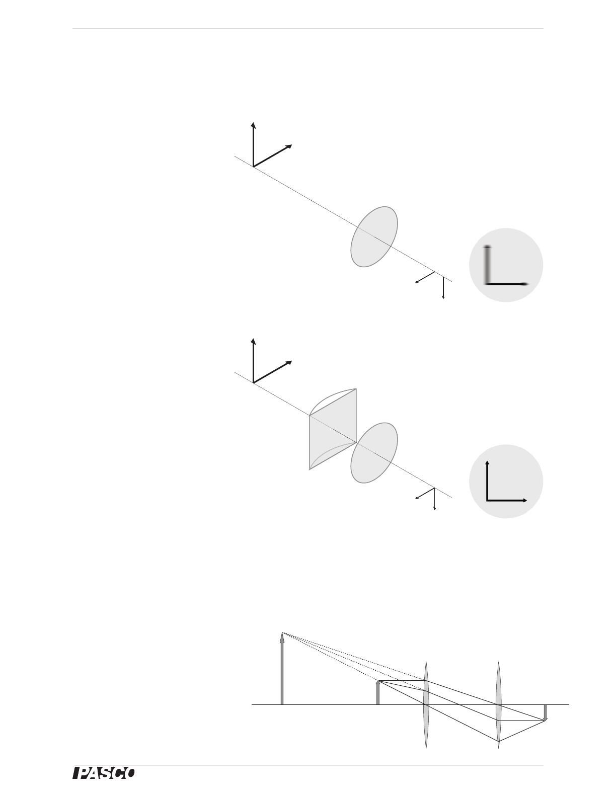
In the example illustrated (right),
the vertical- and horizontal-line
objects are at the same distance,
but the eye’s lens system forms an
image of the vertical line at a
greater distance than the image of
the horizontal line. If the horizon-
tal-line image is formed exactly at
the retina then it appears in focus,
but the vertical-line image is
formed behind the retina and
appears blurred. The corrective
lens causes the vertical- and hori-
zontal-line images to be formed at the same distance.
Optical Instruments
Optical instruments enhance vision by forming an image that is a different size or at a
different position from the object.
A magnifying glass is a single
convergent lens used to view
near objects. It creates a real,
upright image that is larger and
farther away. This makes the
object appear larger, and it allows
the eye to focus on an object that
would normally be closer than
the eye’s near point. The object
distance must be less than the
Vertical- and Horizontal-line Objects
Astigmatic Lens System
of the Eye
Horizontal-line image
formed at the retina
Vertical-line image formed
behind the retina
Corrective Cylindrical Lens
Both images formed
at the retina Perceived
Image
Perceived
Image
ObjectImage Formed by
Magnifying Glass
Magnifying
Glass
Eyes Lens
System
Image Formed
on Retina
®
Human Eye Model Background
12
focal length of the lens. Reading glasses can be thought of as a type of magnifying
glass that allow you to hold a book nearer than your eyes’ near point while viewing a
more distant image of the book.
A microscope is a combination of two or more lenses that forms a distant image of a
near object. In the example illustrated below, a system of two converging lenses
forms an upright, real image at infinity
A telescope forms a larger image of a distant object. In the example of a simple tele-
scope illustrated below, a system of two converging lenses forms an inverted, real
image. Note that the image is not closer to the eye than the object; this telescope
forms a distant image which can be viewed by the eye in its relaxed state, when it is
focused at infinity.
Because its objective lens, or first lens, usually has a larger area than the pupil of the
eye, a telescope gathers more light than the unaided eye, and thus can allow the eye to
see objects that would normally be too dim to detect.
Object
Image Formed
by Microscope
at Infinity
Microscope
Eyes Lens
System
Image Formed
on Retina
Object
Image Formed by
Telescope
Telescope
Eyes Lens
System
Image Formed
on Retina
®
13
Human Eye Model
Experiment Setup
This table summarizes the equipment needed for the following experiments. With the
exception of the eye model itself, the specific model numbers suggested here can be
substituted with similar items from PASCO or other manufacturers. See “Equipment
and Procedure Notes” below for details.
Equipment and Procedure Notes
Light Sources and Objects
In these experiments, you will use the eye model to form images on the retina screen.
The room should be fairly dark to make the images easier to see. It is helpful to have
a desk lamp at your lab station that you can turn on and off and shine inside the eye
model when you change lenses.
The illuminated screen of the OS-8470 Basic Optics Light Source (or a similar light
source) is recommended for use as a “near” object, but a pattern drawn on a sheet of
paper and brightly illuminated with your desk lamp will work as well. For informal
experimentation, you can use the desk lamp to light up almost any object (such as
your hand, a book, or your lab partners face) to form an image in the eye model.
In addition to nearby objects, you will need a distance object that the eye model can
focus on. A single, small window or open door with a view to the outside works best,
but a bright lamp at the far end of the room will do. Make sure that you can position
the eye model on your lab bench to see the distant object.
Equipment Needed Model Number
Human Eye Model OS-8477A
Basic Optics Light Source1
1Or other illuminated “near” object, see below.
OS-8470 or part of OS-8515C
Basics Optics System2
2Required only for Experiment 2. Components called for are a 120 cm bench,
a light source, lenses with focal lengths of +100, +200 mm, and -150 mm; a
viewing screen; and adjustable lens holder.
OS-8515C
Mounting Bracket3
3For use with Basic Optics System.
OS-8469
Large-diameter +200 mm lens4
4Optional for Experiment 2 Further Study.
Desk Lamp
“Far” Object (window, door, or lamp)
Meter Stick or Tape Measure
Paper Towel
Water, approximately 1 liter
®
Human Eye Model Experiment Setup
14
Water
They eye model requires about one liter of water, but do not fill it yet if you are going
to do Experiment 1. When you remove lenses from the model, they will be wet; have
an absorbent cloth or paper towel ready to lay them on. Do not wipe or rub the lenses
to dry them; they are made of uncoated plastic and are easily scratched.
Optics Bench
Experiment 2 (the telescope) calls for the optics bench and lenses of the OS-8515A
Basic Optics system or OS-8471 Dynamics Track Optics Kit. For the other experi-
ments, an optics bench is not required, but can be useful for measuring distances. To
raise the eye model to the optical axis of the lenses, use the OS-8469 Eye Model
Mounting Bracket (with the OS-8515A system) or a book about 5 cm thick (with
either type of bench). Any other optics bench system will also work if you can posi-
tion the eye model at the level of the lenses. Experiment 2 calls for lenses with focal
lengths of +100 mm and +200 mm.
Image Size and Distance Measurement
To quantitatively study magnification, you will need to measure the sizes of under-
water images on the retina screen. Since it is difficult to read a ruler under water, the
model comes with a glow-in-the-dark optics caliper. Dip the caliper into the water and
adjust it to span the side-to-side width of the image. For approximate measurement,
use the scale printed on the caliper. For precise measurement, bring the caliper out of
the water and measure the span with a ruler.
Use a meter stick or tape measure to measure the distance between near objects and
the eye model. (It is not necessary to measure the distance to the “far” object.) If you
are using an optics bench, you can use the scale on the bench, but you may find it eas-
ier to use a ruler to measure distances between components inside the eye model.
Clean Up
Do not wipe or rub the lenses to dry them. Wet lenses can be placed in the foam
holder. After removing the lenses and retina screen, carefully pour the water out
through the spout on the back rim of the eye model. Allow all parts to dry before stor-
ing them in a closed space.
OS-8468 - Optics Caliper: Expose to light to activate glow-in-the-dark markings.
For use with Human Eye Model (OS-8469) or diffraction pattern measurements.
10
9
8
7
6
5
4
3
2
1
®
OS-8468
OPTICS
CALIPER
(cm)
10
9
8
7
6
5
4
3
2
1
®
OS-8468
OPTICS
CALIPER
(cm)
Use optics caliper to
measure the width
of an image on the
retina
Pour Spout
®
15
Human Eye Model
Experiment 1: Optics of the Human Eye
In this experiment you will study how images are formed on the retina of the eye.
Before you start, draw a diagram of the eye model and identify the parts of the human
eye represented by each part of the model.
Part 1: Images Formed in the Eye
Procedure
1. Do not fill the eye model with water yet. Put the retina screen in the middle slot,
marked NORMAL. Put the +400 mm lens in the slot labeled SEPTUM.
2. Put your hand in front of the eye model, about 50 cm from the cornea. Use your
desk lamp to brightly illuminate your hand. Can you see an image on the retina
screen? Move your hand up, down, left, and right. How does the image move?
3. Draw an asymmetrical picture on a sheet of paper and hold it in front of the eye
model. Is the image of your picture on the retina inverted? Turn the picture
upside down. How does the image look now? Sketch the retina image and draw a
copy of the original picture next to it.
Questions
1. Since the image on the retina is inverted, why do we not see things upside down?
2. If you wrote something on a piece of paper and held it upside down in front of the
eye, how would it look on the retina? Would you be able to read it easily?
Retina
+400 mm Lens
®
Human Eye ModelExperiment 1: Optics of the Human Eye
16
Part 2: Accommodation
In the process of accommodation, muscles in the eye change the shape of the crystal-
line lens to change its focal length. Initially, you will model accommodation by vary-
ing the focal length of the crystalline lens using the adjustable focus lens. Later, when
the model is filled with water, accommodation is achieved by replacing the crystalline
lens with fixed lenses of various focal lengths.
Procedure
Note: If you have not done so yet, follow the instructions of page 5 to fill the adjustable focus lens
with water.
1. Do not fill the eye model with water yet. Replace with lens in the SEPTUM slot
with the adjustable focus lens. Position the eye model about 25 cm from the illu-
minated screen.
Can you see the image on the retina? Move the syringe plunger to adjust the lens
and form the clearest image possible.
Is the lens concave or convex? Is it a converging lens or a diverging lens?
2. Move the eye model farther from the illuminated screen to about 50 cm. Adjust
the lens again to form the clearest image.
Did you increase or decrease the power of the lens? Did you increase or decrease
the focal length?
3. Replace the adjustable focus lens with the +400 mm lens in the SEPTUM slot.
Adjust the distance of the illuminated screen to form a clear image. Mark the
position of the eye model so you can return it to the same place after you fill it
with water.
4. Fill the eye model with water to within 1 or 2 cm of the top. Return it to the same
position as in step 3.
Is the image still in focus? Try changing the distance; can you get it to focus?
Explain. What effect do the aqueous and vitreous humors (modeled by the water)
have on the focal length of the eye’s lens system?
5. Place the eye model about 35 cm from the light source. Replace the +400 mm
lens in the SEPTUM slot with the +62 mm lens.
Is the image in focus now? Move the eye model as close as possible to the light
source while keeping the image in focus. Describe the image on the retina screen.
6. Measure the object distance, o, from the screen of the light source to the top rim
of the eye model, as pictured below. (The front of the rim is a convenient place to
measure to and marks the center of the eye model’s two-lens system.) Record this
distance, which is the near point of the eye model when equipped with the
+62 mm lens. The average human eye has a near point for distinct vision of about
25 cm.
+62 mm Lens
®
Model No. OS-8477A Experiment 1: Optics of the Human Eye
17
7. The optics of a two-lens system can be simplified looking at the combined effect
of the lenses and the total effective focal length of the system. Measure the image
distance (i), from the model’s rim to the handle of the retina. Calculate the total
effective focal length ( f) of the two-lens system using the thin lens formula:
8. Increase the ability of the eye model to focus on a close object by adding the
+400 mm lens to slot B. This combination models a different focal length for the
crystalline lens.
How close can the eye focus now?
9. Keep the +400 mm lens in slot B and replace the lens in the SEPTUM slot with
the +120 mm lens.
At what distance does the model eye focus now? What does a real human eye do
to change the focal length of the its crystalline lens?
10. Remove both lenses and place the +62 mm lens in the
SEPTUM slot. Adjust the eye-source distance to the
“near point” distance for this lens (which you found in
step 6) so that the image is in focus. While looking at the
image, place the round pupil in slot A.
What changes occur in the brightness and clarity of the
image? Move the light source several centimeters closer
to the eye model. Is the image still in focus? Remove the
pupil and observe the change in clarity of the image. Both
with and without the pupil, how much can you change the
eye-source distance and still have a sharp image?
Predict what will happen to the image when you place the “cat’s pupil” in slot A.
Try it and record your observations.
11. Make a detailed drawing showing the object, image, pupil, and both lenses. Iden-
tify which lens models the corneal lens and which models the crystalline lens.
12. Position the eye model (with pupil removed) so that it is looking towards a
distant object. Is the image on the retina in focus? Replace the lens in the SEP-
TUM slot with one that makes a clear image of the distant object; this is the far-
vision lens. Record the focal length marked on the handle of the lens.
image
distance
1
f
---1
i
---1
o
---
+=
+400 mm Lens
Pupil
+62 mm Lens
Round
Pupil
Cats
Pupil
®
Human Eye ModelExperiment 1: Optics of the Human Eye
18
13. Calculate the total effective focal length of the lens system, as you did in step 7.
What value should you use as the object distance for far vision? How do you
enter that value into a calculator? (Hint: as the object distance, o, increases
towards infinity, the inverse of the object distance, 1/o, decreases towards zero.)
14. One treatment for cataracts is to surgically remove the crystalline lens. Remove
the crystalline lens from the eye model and observe the image of the distant
object on the retina. Can an unaided eye without a crystalline lens focus on dis-
tant objects?
Place the +400 mm lens in slot 1 to act as an eyeglasses lens. Does this restore
clear vision? Turn the eye model to look at the nearby light source. Can you
adjust the near object distance to form a clear image? Replace the eyeglasses lens
in slot 1 with the +120 mm lens. Now can you adjust the object distance to form
a clear image?
Questions
1. Compare the crystalline lens needed for far vision to the crystalline lens needed
for near vision? Which lens is more curved? When you look through them, which
lens appears to be stronger? Compare the effective focal lengths (of the two-lens
systems) for near and far vision that you calculated in steps 7 and 13.
2. In step 13, the effective focal length (f) and the image distance (i) were the same.
Why? For what special case does f equal i?
3. In a real human eye, accommodation is accomplished by muscles that change the
curvature of the crystalline lens. When an eye changes accommodation from a
distant object to a near object, does the curvature of the crystalline lens increase
or decrease? Why does the eye’s range of accommodation decrease with age?
4. In step 14, you showed that, with the aid of eyeglasses, it is possible to focus an
image after the crystalline lens has been removed. Is this an ideal solution for cat-
aract patients? Explain. (Hint: which lens is responsible for accommodation?
What would a person without crystalline lenses need to do to clearly see objects
at different distances?) How do modern cataract treatments improve upon this
older surgical technique?
Part 3: Far-sightedness (Hypermetropia)
A person affected by hypermetropia has a shorter-than-normal eye ball, making the
retina too close to the lens system. This causes images of near objects to be formed
behind the retina.
Procedure
1. Set the eye model to normal near vision (put the 62 mm lens in the SEPTUM slot,
remove other lenses, and make sure the retina is in the NORMAL position). Posi-
tion the eye to look at the nearby light source. Adjust the eye-source distance to
the near-point distance so that the image is in focus.
2. Move the retina screen to the forward slot, labeled FAR. Describe what happens
to the image. This is what a far-sighted person sees when trying to look at a near
object.
Decrease the pupil size by placing the round pupil in slot A. What happens to the
clarity of the image? Remove the pupil.
+400 mm Lens
+62 mm Lens
Retina
  • Page 1 1
  • Page 2 2
  • Page 3 3
  • Page 4 4
  • Page 5 5
  • Page 6 6
  • Page 7 7
  • Page 8 8
  • Page 9 9
  • Page 10 10
  • Page 11 11
  • Page 12 12
  • Page 13 13
  • Page 14 14
  • Page 15 15
  • Page 16 16
  • Page 17 17
  • Page 18 18
  • Page 19 19
  • Page 20 20
  • Page 21 21
  • Page 22 22
  • Page 23 23
  • Page 24 24
  • Page 25 25
  • Page 26 26
  • Page 27 27
  • Page 28 28
  • Page 29 29
  • Page 30 30
  • Page 31 31
  • Page 32 32
  • Page 33 33
  • Page 34 34
  • Page 35 35
  • Page 36 36
  • Page 37 37
  • Page 38 38
  • Page 39 39
  • Page 40 40
  • Page 41 41
  • Page 42 42

PASCO OS-8477A Owner's manual

Type
Owner's manual
This manual is also suitable for

Ask a question and I''ll find the answer in the document

Finding information in a document is now easier with AI