Page is loading ...

Part No. P0609345 01
March 15, 2004
Business Communications
Manager
Companion Configuration
Guide

2
P0609345 01
Copyright © 2004 Nortel Networks
All rights reserved.
The information in this document is subject to change without notice. The statements, configurations, technical data, and
recommendations in this document are believed to be accurate and reliable, but are presented without express or implied
warranty. Users must take full responsibility for their applications of any products specified in this document. The
information in this document is proprietary to Nortel Networks NA Inc.
Trademarks
NORTEL NETWORKS is a trademark of Nortel Networks.
Microsoft, MS, MS-DOS, Windows, and Windows NT are registered trademarks of Microsoft Corporation.
All other trademarks and registered trademarks are the property of their respective owners.

Contents 3
Business Communications Manager Companion Configuration Guide
Contents
Preface . . . . . . . . . . . . . . . . . . . . . . . . . . . . . . . . . . . . . . . . . . . . . . . . . . . . . . . 9
Before you begin . . . . . . . . . . . . . . . . . . . . . . . . . . . . . . . . . . . . . . . . . . . . . . . . . . . . . . 9
Symbols used in this guide . . . . . . . . . . . . . . . . . . . . . . . . . . . . . . . . . . . . . . . . . . . . . . 9
Text conventions . . . . . . . . . . . . . . . . . . . . . . . . . . . . . . . . . . . . . . . . . . . . . . . . . . . . . 10
How to get help . . . . . . . . . . . . . . . . . . . . . . . . . . . . . . . . . . . . . . . . . . . . . . . . . . . . . . 10
Chapter 1
Installing the Companion system. . . . . . . . . . . . . . . . . . . . . . . . . . . . . . . . . 13
Companion components overview . . . . . . . . . . . . . . . . . . . . . . . . . . . . . . . . . . . . . . . . 14
Hardware installation process map . . . . . . . . . . . . . . . . . . . . . . . . . . . . . . . . . . . . . . . 15
Remote power interconnect (RPI) unit overview . . . . . . . . . . . . . . . . . . . . . . . . . . . . . 16
Mounting the RPI unit . . . . . . . . . . . . . . . . . . . . . . . . . . . . . . . . . . . . . . . . . . . . . . . . . 17
Wiring the base station and connecting the RPI . . . . . . . . . . . . . . . . . . . . . . . . . . . . . 19
Connecting the RPI . . . . . . . . . . . . . . . . . . . . . . . . . . . . . . . . . . . . . . . . . . . . . . . . 20
RPI output connections . . . . . . . . . . . . . . . . . . . . . . . . . . . . . . . . . . . . . . . . . . . . . 21
RPI input connections . . . . . . . . . . . . . . . . . . . . . . . . . . . . . . . . . . . . . . . . . . . . . . 21
RPI-8 BIX wiring chart . . . . . . . . . . . . . . . . . . . . . . . . . . . . . . . . . . . . . . . . . . . . . . 22
RPI-8 BIX wiring chart . . . . . . . . . . . . . . . . . . . . . . . . . . . . . . . . . . . . . . . . . . . . . . 24
Companion base station installation overview . . . . . . . . . . . . . . . . . . . . . . . . . . . . . . . 25
Positioning a Companion base station . . . . . . . . . . . . . . . . . . . . . . . . . . . . . . . . . 26
Attaching a Companion base station . . . . . . . . . . . . . . . . . . . . . . . . . . . . . . . . . . 27
Installing the base station . . . . . . . . . . . . . . . . . . . . . . . . . . . . . . . . . . . . . . . . . . . 27
Registering Companion telephones . . . . . . . . . . . . . . . . . . . . . . . . . . . . . . . . . . . . . . 29
Restarting the system after a software update . . . . . . . . . . . . . . . . . . . . . . . . . . . . . . 29
Installing external antennas and lightning surge protection . . . . . . . . . . . . . . . . . . . . . 30
Read before you install equipment . . . . . . . . . . . . . . . . . . . . . . . . . . . . . . . . . . . . 30
Installing antennas (United States of America) . . . . . . . . . . . . . . . . . . . . . . . . . . . 31
Before you install an outdoor antenna (USA). . . . . . . . . . . . . . . . . . . . . . . . . . . . . 31
Installing an outdoor antenna (USA) . . . . . . . . . . . . . . . . . . . . . . . . . . . . . . . . . . . 32
Installing a lightning surge protector (USA) . . . . . . . . . . . . . . . . . . . . . . . . . . . . . . 34
Installing antennas (Canada) . . . . . . . . . . . . . . . . . . . . . . . . . . . . . . . . . . . . . . . . 35
Outdoor requirements . . . . . . . . . . . . . . . . . . . . . . . . . . . . . . . . . . . . . . . . . . . . . . 35
Installing an indoor directional antenna . . . . . . . . . . . . . . . . . . . . . . . . . . . . . . . . . 36
Installing an indoor omnidirectional antenna (Canada) . . . . . . . . . . . . . . . . . . . . . 37
Installing an outdoor omnidirectional antenna (Canada) . . . . . . . . . . . . . . . . . . . . 38
Installing a lightning surge protector (Canada) . . . . . . . . . . . . . . . . . . . . . . . . . . . 40
Chapter 2
Configuring Companion handsets . . . . . . . . . . . . . . . . . . . . . . . . . . . . . . . . 41
Companion overview . . . . . . . . . . . . . . . . . . . . . . . . . . . . . . . . . . . . . . . . . . . . . . . . . . 42

4 Contents
P0609345 01
Process map: Companion portable handset . . . . . . . . . . . . . . . . . . . . . . . . . . . . . . . . 43
Defining radio data . . . . . . . . . . . . . . . . . . . . . . . . . . . . . . . . . . . . . . . . . . . . . . . . . . . 44
Using Reevaluation to assign cells to base stations . . . . . . . . . . . . . . . . . . . . . . . 44
Programming base station radios . . . . . . . . . . . . . . . . . . . . . . . . . . . . . . . . . . . . . 44
Defining base station cells . . . . . . . . . . . . . . . . . . . . . . . . . . . . . . . . . . . . . . . . . . 45
Enabling Companion handset registration . . . . . . . . . . . . . . . . . . . . . . . . . . . . . . . . . . 46
Enabling registration or changing the password . . . . . . . . . . . . . . . . . . . . . . . . . . 46
Using portable DNs to show handset status . . . . . . . . . . . . . . . . . . . . . . . . . . . . . . . . 47
Registering Companion portables . . . . . . . . . . . . . . . . . . . . . . . . . . . . . . . . . . . . . . . . 48
Registering the C3060 handset . . . . . . . . . . . . . . . . . . . . . . . . . . . . . . . . . . . . . . . 48
Confirm that the handset is registered . . . . . . . . . . . . . . . . . . . . . . . . . . . . . . . . . . 49
Registering the C3050 handset . . . . . . . . . . . . . . . . . . . . . . . . . . . . . . . . . . . . . . . 50
Confirm that the handset is registered . . . . . . . . . . . . . . . . . . . . . . . . . . . . . . . . . . 51
Registering a C3020 handset (Canada only) . . . . . . . . . . . . . . . . . . . . . . . . . . . . 52
Confirm that the handset is registered . . . . . . . . . . . . . . . . . . . . . . . . . . . . . . . . . . 52
Deregistering a handset . . . . . . . . . . . . . . . . . . . . . . . . . . . . . . . . . . . . . . . . . . . . . . . 53
Deregistering a portable from the system . . . . . . . . . . . . . . . . . . . . . . . . . . . . . . . 53
Deregistering a C3060 handset . . . . . . . . . . . . . . . . . . . . . . . . . . . . . . . . . . . . . . 54
Deregistering a C3050 handset . . . . . . . . . . . . . . . . . . . . . . . . . . . . . . . . . . . . . . 54
Deregistering a C3020 handset . . . . . . . . . . . . . . . . . . . . . . . . . . . . . . . . . . . . . . 55
Measuring RSSI for the handsets . . . . . . . . . . . . . . . . . . . . . . . . . . . . . . . . . . . . . . . . 55
Measuring undirected RSSI for C3060 handsets. . . . . . . . . . . . . . . . . . . . . . . . . . 56
Measuring directed RSSI for C3060 handsets. . . . . . . . . . . . . . . . . . . . . . . . . . . . 56
Measuring undirected RSSI for C3050 handsets. . . . . . . . . . . . . . . . . . . . . . . . . . 57
Measuring directed RSSI for C3050 handsets. . . . . . . . . . . . . . . . . . . . . . . . . . . . 57
Measuring undirected RSSI for C3020 handsets. . . . . . . . . . . . . . . . . . . . . . . . . . 58
Measuring directed RSSI for C3020 handsets. . . . . . . . . . . . . . . . . . . . . . . . . . . . 58
Companion DN record parameters . . . . . . . . . . . . . . . . . . . . . . . . . . . . . . . . . . . . . . . 59
Handset features and restrictions . . . . . . . . . . . . . . . . . . . . . . . . . . . . . . . . . . . . . . . . 60
Feature access for Companion . . . . . . . . . . . . . . . . . . . . . . . . . . . . . . . . . . . . . . . 61
Language selection . . . . . . . . . . . . . . . . . . . . . . . . . . . . . . . . . . . . . . . . . . . . . . . . 62
Index . . . . . . . . . . . . . . . . . . . . . . . . . . . . . . . . . . . . . . . . . . . . . . . . . . . . . . . . 63

5
Business Communications Manager Companion Configuration Guide
Figures
Figure 1 Process map: Installing Companion support hardware . . . . . . . . . . . . . . . . . . . 15
Figure 2 RPI unit . . . . . . . . . . . . . . . . . . . . . . . . . . . . . . . . . . . . . . . . . . . . . . . . . . . . . . . 16
Figure 3 RPI mounting holes . . . . . . . . . . . . . . . . . . . . . . . . . . . . . . . . . . . . . . . . . . . . . . 17
Figure 4 Opening the RPI cover . . . . . . . . . . . . . . . . . . . . . . . . . . . . . . . . . . . . . . . . . . . . 18
Figure 5 RPI components . . . . . . . . . . . . . . . . . . . . . . . . . . . . . . . . . . . . . . . . . . . . . . . . . 18
Figure 6 RPI connector printed-circuit board . . . . . . . . . . . . . . . . . . . . . . . . . . . . . . . . . . 20
Figure 7 Output connector pinout . . . . . . . . . . . . . . . . . . . . . . . . . . . . . . . . . . . . . . . . . . . 21
Figure 8 Input connector pinout . . . . . . . . . . . . . . . . . . . . . . . . . . . . . . . . . . . . . . . . . . . . 21
Figure 9 Bracket termination board . . . . . . . . . . . . . . . . . . . . . . . . . . . . . . . . . . . . . . . . . 27
Figure 10 Slide the cover on bracket . . . . . . . . . . . . . . . . . . . . . . . . . . . . . . . . . . . . . . . . . 28
Figure 11 Installed antenna and lightning surge protectors (USA) . . . . . . . . . . . . . . . . . . 31
Figure 12 Antenna with antenna bracket (USA) . . . . . . . . . . . . . . . . . . . . . . . . . . . . . . . . . 33
Figure 13 Lightning surge protector and bracket (USA) . . . . . . . . . . . . . . . . . . . . . . . . . . . 34
Figure 14 Indoor directional external antenna (Canada) . . . . . . . . . . . . . . . . . . . . . . . . . . 36
Figure 15 Indoor omnidirectional external antenna (Canada) . . . . . . . . . . . . . . . . . . . . . . 37
Figure 16 Install the outdoor omnidirectional external antenna (Canada) . . . . . . . . . . . . . 39
Figure 17 Install the lightning surge protector (Canada) . . . . . . . . . . . . . . . . . . . . . . . . . . 40
Figure 18 Companion headings . . . . . . . . . . . . . . . . . . . . . . . . . . . . . . . . . . . . . . . . . . . . . 41
Figure 19 Process map: Setting up Companion handsets for registration . . . . . . . . . . . . . 43

6
P0609345 01

7
Business Communications Manager Companion Configuration Guide
Tables
Table 1 RPI Requirements . . . . . . . . . . . . . . . . . . . . . . . . . . . . . . . . . . . . . . . . . . . . . . . 17
Table 2 Cable distances . . . . . . . . . . . . . . . . . . . . . . . . . . . . . . . . . . . . . . . . . . . . . . . . . 19
Table 3 Input wiring . . . . . . . . . . . . . . . . . . . . . . . . . . . . . . . . . . . . . . . . . . . . . . . . . . . . . 22
Table 4 RPI-8 BIX wiring chart . . . . . . . . . . . . . . . . . . . . . . . . . . . . . . . . . . . . . . . . . . . . 22
Table 5 RPI-16 BIX wiring chart . . . . . . . . . . . . . . . . . . . . . . . . . . . . . . . . . . . . . . . . . . . 24
Table 6 Minimum distance between office areas and base stations . . . . . . . . . . . . . . . . 26
Table 7 Clearance for the base stations . . . . . . . . . . . . . . . . . . . . . . . . . . . . . . . . . . . . . 27
Table 8 UTAM messages . . . . . . . . . . . . . . . . . . . . . . . . . . . . . . . . . . . . . . . . . . . . . . . . 29
Table 9 Radio settings . . . . . . . . . . . . . . . . . . . . . . . . . . . . . . . . . . . . . . . . . . . . . . . . . . 44
Table 10 Cell information . . . . . . . . . . . . . . . . . . . . . . . . . . . . . . . . . . . . . . . . . . . . . . . . . 45
Table 11 Handset registration and password information . . . . . . . . . . . . . . . . . . . . . . . . . 46
Table 12 Companion telephone programming . . . . . . . . . . . . . . . . . . . . . . . . . . . . . . . . . 59
Table 13 Features available to a Companion portable handset . . . . . . . . . . . . . . . . . . . . 61

8
P0609345 01

9
Business Communications Manager Companion Configuration Guide
Preface
This guide explains how to install and program Companion base stations and handsets.
Before you begin
This guide assumes the following:
• The Business Communications Manager is installed and initialized, and all hardware appears
to be working.
• That a site survey has been conducted and the installer has access to these plans.
• That all configuration operators have a working knowledge of the Windows operating system
and graphical user interfaces.
Symbols used in this guide
This guide uses symbols to draw your attention to important information. The following symbols
appear in this guide:
Caution: Caution Symbol
Alerts you to conditions where you can damage the equipment.
Danger: Electrical Shock Hazard Symbol
Alerts you to conditions where you can get an electrical shock.
Warning: Warning Symbol
Alerts you to conditions where you can cause the system to fail or work improperly.
Note: Note Symbol
A Note alerts you to important information.
Tip: Tip Symbol
Alerts you to additional information that can help you perform a task.
!
Security Note: This symbol indicates a point of system security where a default should
be changed, or where the administrator needs to make a decision about the level of
security required for the system.

10 Preface
P0609345 01
Text conventions
This guide uses the following text conventions:
How to get help
If you do not see an appropriate number in this list, go to www.Nortelnetworks.com/support.
USA and Canada
Authorized Distributors - ITAS Technical Support
Telephone: 1-800-4NORTEL (1-800-466-7835)
If you already have a PIN Code, you can enter Express Routing Code (ERC) 196#.
If you do not yet have a PIN Code, or for general questions and first line support, you can enter
ERC 338#.
Website: http://www.nortelnetworks.com/support
Presales Support (CSAN)
Telephone: 1-800-4NORTEL (1-800-466-7835)
Use Express Routing Code (ERC) 1063#
EMEA (Europe, Middle East, Africa)
angle brackets (< >) Indicates that you choose the text to enter based on the description
inside the brackets. Do not type the brackets when entering the
command.
Example: If the command syntax is:
ping <ip_address>
you enter: ping 192.32.10.12
bold Courier text
Indicates command names and options and text that you need to enter.
Example: Use the
dinfo command.
Example: Enter show ip {alerts|routes}.
italic text Indicates book titles
plain Courier
text
Indicates command syntax and system output, for example, prompts
and system messages.
Example:
Set Trap Monitor Filters
FEATURE
HOLD
RELEASE
Indicates that you press the button with the coordinating icon on
whichever set you are using.

Preface 11
Business Communications Manager Companion Configuration Guide
Technical Support - CTAS
Telephone:
*European Freephone 00800 800 89009
European Alternative/
United Kingdom +44 (0)870-907-9009
Africa +27-11-808-4000
Israel 800-945-9779
*Note: Calls are not free from all countries in Europe, Middle East or Africa
Fax: 44-191-555-7980
email: emeahelp@nortelnetworks.com
CALA (Caribbean & Latin America)
Technical Support - CTAS
Telephone: 1-954-858-7777
email: csrmgmt@nortelnetworks.com
APAC (Asia Pacific)
Technical Support - CTAS
Telephone: +61-2-870-8800
Fax: +61 388664644
email: asia_support@nortelnetworks.com
In-country toll free numbers
Australia 1800NORTEL (1800-667-835)
China 010-6510-7770
India 011-5154-2210
Indonesia 0018-036-1004
Japan 0120-332-533
Malaysia 1800-805-380
New Zealand 0800-449-716
Philippines 1800-1611-0063
Singapore 800-616-2004
South Korea 0079-8611-2001
Taiwan 0800-810-500
Thailand 001-800-611-3007
Service Business Centre & Pre-Sales Help Desk +61-2-8870-5511

12 Preface
P0609345 01

13
Business Communications Manager Companion Configuration Guide
Chapter 1
Installing the Companion system
This section describes the process for installing a Companion wireless system.
The following information is based on the following understandings:
• A site survey has been completed and you have determined the exact locations of the base
stations around your site.
• You have determined how many handsets you want.
To determine this, you need to know whether your system has a DS30 channel 2/6 or 3/5 split.
• The Companion requires a DSM8 module for every 32 handsets. You can assign a maximum
of 32 Companion handsets per DSM because the Companion system can use both B channels.
You can install a maximum of two DSM8s or one DSM32 for Companion handsets, per
system, providing your system is configured with a DS30 channel 2/6 split. Refer to the
Business Communications Manager Installation and Maintenance Guide for detailed
hardware configuration.
The Companion hardware must be in place and configured before you can use the handsets to
connect to the Business Communications Manager. This section describes the installation of the
various pieces of hardware.
This section contains the following information:
• “Companion components overview” on page 14
• “Hardware installation process map” on page 15
• “Companion components overview” on page 14
• “Remote power interconnect (RPI) unit overview” on page 16
• “Mounting the RPI unit” on page 17
• “Wiring the base station and connecting the RPI” on page 19
• “Companion base station installation overview” on page 25
• “Positioning a Companion base station” on page 26
• “Attaching a Companion base station” on page 27
• “Installing external antennas and lightning surge protection” on page 30

14 Chapter 1 Installing the Companion system
P0609345 01
Companion components overview
Your Companion portable telephone allows you to leave your desk without missing telephone
calls. The telephones can access most Business Communications Manager business features such
as call forward, call transfer, voice conference, and voice messaging using feature codes.
Business Communications Manager Companion has four main components:
Software - Companion software manages the telephone traffic between Companion base stations
and portable telephones. Base stations connect to the Business Communications Manager in the
same way that Business Communications Manager telephones do. You register the Companion
portable telephones on the system. They do not require any ports on the system. You can connect a
maximum of 60 portable telephones and a maximum of 32 base stations (32 cells) to the system.
Note: If you choose a 3/5 channel split for your system, you cannot assign a module to channel 7.
This limits you to a maximum of 16 base stations, which can support a maximum of 30 handsets.
Companion base stations — Position the base stations around the coverage area to send and
receive calls between the portable telephones and Business Communications Manager. Base
stations use digital radio technology and support handoff and roaming within the coverage area.
The coverage area can be a maximum of 160,000 square meters (1,700,000 square feet) when
using the maximum number of base stations. The base station can use internal or external
antennas. For most installations, the internal antenna will be used. If you need to install external
antennas, refer to “Installing external antennas and lightning surge protection” on page 30.
Companion wireless handsets — Business Communications Manager supports the following
wireless handsets: Companion 3020, Companion C3050 Etiquette, Companion C3050 CT2Plus,
and Companion C3060.
The portable telephones used with your Business Communications Manager system are small,
lightweight units with complete digital performance to provide clear voice quality. Companion
portable telephones feature a three-line, 16-character, alphanumeric display.
Administration and maintenance tools — Programming of the Companion system is easily and
quickly done through the Business Communications Manager Unified Manager. You can assign
portable telephones to the system, check base station parameters, and enable and disable
registration through programming.
Companion Diagnostics software allows you to run diagnostics on the wireless system. You run
the diagnostics using a personal computer located at the customer site or in a remote location.

Chapter 1 Installing the Companion system 15
Business Communications Manager Companion Configuration Guide
Hardware installation process map
The following figure provides an overview of the process for installing the support hardware for a
Companion wireless system.
Figure 1 Process map: Installing Companion support hardware
Note: Companion wireless availability is region-specific. This option also requires a software
keycode for activation.
DSM module
installed and
configured
Install remote power
interconnect (RPI)
Install external
antennas and
lightning protection,
if required
Install base stations
Restore system
to operation
Register Companion sets*
Business
Communications
Manager
Companion
equipment
Connect base stations to DSM
Configure DN
records for the
handsets
*In the United States, you must enter
a UTAM keycode before you register
the handsets.

16 Chapter 1 Installing the Companion system
P0609345 01
Remote power interconnect (RPI) unit overview
The remote power interconnect unit (RPI) provides remote power for base station support.
The following figure shows a diagram of the RPI.
Figure 2 RPI unit
There are two versions of the RPI unit:
• The RPI-8 BIX UL supports a maximum of eight base stations.
• The RPI-16 BIX UL supports a maximum of 16 base stations.
Each RPI has a connection printed-circuit board and either one (RPI-8 BIX UL) or two (RPI-16
BIX UL) power supply units (PSUs). The maximum input power consumption of an RPI is 240 W.
If you use a UPS 48 V dc backup source, the maximum input power requirement of the RPI is
140 W.
You can upgrade an RPI-8 BIX UL to an RPI-16 BIX UL by installing a second PSU to the RPI-8
BIX UL.
Caution: The RPI unit must have the DC backup power supplied by a UL listed universal
power supply (UPS).
The UPS must have an output voltage rating of 44 to 52 V DC, with a maximum fault
current limit of 6 A to protect the RPI output wiring. If these requirements are not met, it is
necessary to use class 1 wiring.
Warning: You must install the RPI units inside a building.
The AC outlet powering the RPI must be installed near the equipment and must be easily
accessible.
The length of the RPI cord, from the outside surface of the unit to the plug, must be a
minimum of 1.3 m (4.5 ft) and a maximum of 4.6 m (15 ft).

Chapter 1 Installing the Companion system 17
Business Communications Manager Companion Configuration Guide
If you distribute the RPIs around the site, the number and type of RPIs depend on where you place
them and how you power the base stations.
To determine how many base stations and how many PSUs you need for the number of base
stations, use the following table:
Mounting the RPI unit
When you mount the RPI unit, ensure you are following these guidelines before you start with
step 1 below:
• Leave a clearance of a minimum of 125 mm (5 in.) around the RPI to provide acceptable
ventilation and to prevent overheating.
• Leave a clearance of a minimum of 300 mm (12 in.) between two RPIs if you are installing
them above one another, to provide acceptable ventilation and to prevent overheating.
• Install RPIs a minimum of 300 mm (12 in.) from the ceiling.
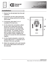
1 Partially screw in two #10 50 mm (2 in.) screws using the keyholes in the back of the unit, at
the top, as a guide. Refer to the following figure.
Figure 3 RPI mounting holes
2 Open the cover with a screwdriver.
a On the latch on the right side of the unit, use the screwdriver to push in, and then down, to
release the latch.
Table 1 RPI Requirements
Base stations RPI-16 and RPI-8 required PSUs required
1–8 1 RPI-8 1 PSU
9–16 1 RPI-16 2 PSUs
17–24 1 RPI-16 and 1 RPI-8 3 PSUs
25–32 2 RPI-16 4 PSUs
325 mm
(13 in.)
25 mm
(1 in.)
50 mm
(2 in.)
300 mm
(12 in.)
Keyholes

18 Chapter 1 Installing the Companion system
P0609345 01
b Remove the cover by lifting it up. Refer to the following figure.
Figure 4 Opening the RPI cover
3 Hang the RPI on the two screws and tighten the screws.
4 Install the remaining two screws.
5 Feed the power cord through the bottom of the RPI.
6 Route it through the clip and around the strain relief support. The following figure
shows how to route the power cord.
Figure 5 RPI components
7 Route the power cord to the input power socket just to the left of PSU 1, on the left.
8 Connect the plug to the socket.
9 Follow the appropriate wiring instructions in the wiring charts in the next section,
“Wiring the base station and connecting the RPI”.
PSU 1 PSU 2
(if equipped)
Up to 16 outputs
(TCM + power)
Up to
16
inputs
(TCM)
Connection board
Jumper lead to PSU 2
Power cord
Grounding strap
Power supply cabling
Strain relief support
Clip
Grounding plates
Ferrite rings
The RPI-8 has grounding straps and
plates fitted to allow an upgrade to
an RPI-16.

Chapter 1 Installing the Companion system 19
Business Communications Manager Companion Configuration Guide
CAUTION: Do not apply power to the RPI until its installation and wiring are complete.
10 After the cable is wired correctly, connect the RPI power cord to the ac outlet.
11 Label each RPI.
Wiring the base station and connecting the RPI
The maximum two-way DC loop resistance for power pairs, including interconnections for each
base station, is 75 ohms. You need one or two power pairs between the RPI and the base station.
The number of power pairs depends on the wire size of the power pair and the distance between
the base station and the RPI.
This section contains this information:
• “Connecting the RPI” on page 20
• “RPI output connections” on page 21
• “RPI input connections” on page 21
• “RPI-8 BIX wiring chart” on page 22
• “RPI-8 BIX wiring chart” on page 24
The maximum cable distances allowed between the RPI and the base station depend on the size of
wire you use. Refer to the following table.
Caution: Do not run unprotected power cables outdoors.
Table 2 Cable distances
Wire size Single pair Double pair
0.6 mm (22 AWG) 800 m (2,500 ft.) 1200 m (4,000 ft.)
0.5 mm (24 AWG) 500 m (1,500 ft.) 1000 m (3,000 ft.)
Caution: When you use two power pairs, connect both pairs with the same polarity.

20 Chapter 1 Installing the Companion system
P0609345 01
Connecting the RPI
Connect the power pairs to the correct connectors. The following figure shows the location of the
input and output connectors on the RPI connector printed-circuit board.
Figure 6 RPI connector printed-circuit board
OBIX1 OBIX2 OBIX3 OBIX4 OBIX9 OBIX10 OBIX11 OBIX12
OBIX5 OBIX6 OBIX7 OBIX8 OBIX13 OBIX14 OBIX15 OBIX16
IBIX1IBIX3IBIX2IBIX4
0B1X1 0B1X2 0B1X3 0B1X4 0B1X9 0B1X10 0B1X11 0B1X12
0B1X5 0B1X6 0B1X7 0B1X8 0B1X9 0B1X13 0B1X14 0B1X15
IBIX4 IBIX3 IBIX2
IBIX2
/