Page is loading ...

Part No. P0607659 02
September 17, 2003
Business Communications
Manager
BCM1000
Installation and Maintenance
Guide
• Changes for version 3.5 software (new hardware)
• Changes for version 3.0.1 software (initialization)
• Changes for version 3.0 software
• Installation and Maintenance for version 2.5 software

2
P0607659 02
Copyright © 2003 Nortel Networks
All rights reserved. October, 2003.
The information in this document is subject to change without notice. The statements, configurations, technical data, and
recommendations in this document are believed to be accurate and reliable, but are presented without express or implied
warranty. Users must take full responsibility for their applications of any products specified in this document. The
information in this document is proprietary to Nortel Networks NA Inc.
Trademarks
NORTEL NETWORKS and Business Communications Manager, are trademarks of Nortel Networks NA Inc.
Microsoft, MS, MS-DOS, Windows, and Windows NT are registered trademarks of Microsoft Corporation.
Symbol, Spectrum24, and NetVision are registered trademarks of Symbol Technologies, Inc.
All other trademarks and registered trademarks are the property of their respective owners.

3
Installation and Maintenance Guide
North American Regulatory Information
Safety
Business Communications Manager equipment meets all applicable requirements of both the CSA
C22.2 No. 950-95 and UL-1950 Edition 3.
Danger: Risk of shock.
Read and follow installation instructions carefully.
Ensure the Business Communications Manager base unit and Business Communications
Manager expansion unit are unplugged from the power socket and that any telephone or
network cables are unplugged before opening the Business Communications Manager
base unit or Business Communications Manager expansion unit.
If installation of additional hardware and /or servicing is required, disconnect all telephone
cable connections prior to unplugging the Business Communications Manager.
Ensure the switch located on the back of the housing, on the power supply, is set to the
correct input voltage (115 or 230).
Ensure the Business Communications Manager base unit and Business Communications
Manager expansion unit are plugged into the wall socket using a three-prong power cable
before any telephone cables are connected.
Caution: Only qualified persons should service the system.
The installation and servicing of this hardware is to be performed only by service
personnel having appropriate training and experience necessary to be aware of hazards to
which they are exposed in performing a task and of measures to minimize the danger to
themselves or other persons.
Electrical shock hazards from the telecommunication network and AC mains are possible
with this equipment. To minimize risk to service personnel and users, the Business
Communications Manager system must be connected to an outlet with a third-wire ground.
Service personnel must be alert to the possibility of high leakage currents becoming
available on metal system surfaces during power line fault events near network lines.
These leakage currents normally safely flow to Protective Earth ground via the power
cord. Therefore, it is mandatory that connection to an earthed outlet is performed first and
removed last when cabling to the unit. Specifically, operations requiring the unit to be
powered down must have the network connections (central office lines) removed first.

4
P0607659 02
Enhanced 911 Configuration
Radio-frequency Interference
Telecommunication registration
Business Communications Manager equipment meets all applicable requirements of both Industry
Canada CS-03 and US Federal Commission FCC Part 68 and has been registered under files
Industry Canada 332-5980 A and FCC AB6CAN-20705-KF-E (key system),
AB6CAN-20706-MF-E (hybrid system), and AB6CAN-23740-PF-E (PBX system). Connection
of the Business Communications Manager telephone system to the nationwide
telecommunications network is made through a standard network interface jack that you can order
from your local telecommunications company. This type of customer-provided equipment cannot
be used on party lines or coin lines.
Before installing this equipment, users should ensure that it is permissible to be connected to the
facilities of the local telecommunications company. The equipment must also be installed using an
acceptable method of connection. The customer should be aware that compliance with the above
conditions may not prevent degradation of service in some situations.
Repairs to certified equipment should be made by an authorized Canadian maintenance facility
designated by the supplier. Any repairs or alterations made by the user to this equipment, or
equipment malfunctions, may give the telecommunications company cause to request the user to
disconnect the equipment. Users should ensure for their own protection that the electrical ground
connections of the power utility, telephone lines and internal metallic water pipe system, if present,
are connected together. This precaution may be particularly important in rural areas.
Caution: Warning
Local, state and federal requirements for Emergency 911 services supported by Customer
Premises Equipment vary. Consult your telecommunication service provider regarding
compliance with applicable laws and regulations.
Note: For information about 911 configuration, refer to the Enhanced 911 (E911)
Configuration section in the Business Communications Manager 2.5 Programming
Operations Guide.
Warning: Equipment generates RF energy.
This equipment generates, uses, and can radiate radio-frequency energy. If not installed
and used in accordance with the installation manual, it may cause interference to radio
communications. It has been tested and found to comply with the limits for a Class A
computing device pursuant to Part 15 of the FCC Rules and with ICES.003, CLASS A
Canadian EMI Requirements. Operation of this equipment in a residential area is likely to
cause interference, in which case the user, at his or her own expense, will be required to
take whatever measures may be required to correct the interference.

5
Installation and Maintenance Guide
Network Connection
Canada and US
Hearing Aid Compatibility
Business Communications Manager telephones are hearing-aid compatible, as defined in Section
68.316 of Part 68 FCC Rules.
Electromagnetic Compatibility
Business Communications Manager equipment meets all FCC Part 15, Class A radiated and
conducted emissions requirements.
Business Communications Manager does not exceed the Class A limits for radiated and conducted
emissions from digital apparatus as set out in the Radio Interference Regulations of Industry
Canada.
Telephone Company Registration
It is usually not necessary to call the telecommunications company with information on the
equipment before connecting the Business Communications Manager system to the telephone
network. If the telecommunications company requires this information, provide the following:
• telephone number(s) to which the system will be connected
• FCC registration number (on label affixed to Business Communications Manager)
• universal service order code (USOC)
• service order code (SOC)
• facility interface code (FIC)
Caution: Users should not attempt to make such connections themselves, but
should contact the appropriate electric inspection authority, or an electrician.
Table 1 Interface harmonized standards
Interface Harmonized Standard Description
CTM Industry Canada CS03, FCC Part 68 Analog terminal device
DTM Industry Canada CS03, FCC Part 68 T1 and Primary Rate ISDN
BRI Industry Canada CS03, FCC Part 68 Basic Rate ISDN
WAN Industry Canada CS03, FCC Part 68 T1

6
P0607659 02
Use of a Music Source
In accordance with U.S. Copyright Law, a license may be required from the American Society of
Composers, Authors and Publishers, or similar organization if Radio or TV broadcasts are
transmitted through the Music On Hold or Background Music features of this telecommunication
system.
Nortel Networks hereby disclaims any liability arising out of the failure to obtain such a license.
Rights of the Telecommunications Company
If the Business Communications Manager system is causing harm to the telephone network, the
telecommunications company may discontinue service temporarily. If possible, the
telecommunications company will notify you in advance. If advance notice is not practical, the
user will be notified as soon as possible. The user will be given the opportunity to correct the
situation and will be informed of the right to file a complaint to the FCC.
The telecommunications company may make changes in its facilities, equipment, operations or
procedures that could affect the proper functioning of the system. If this happens, the
telecommunications company will give you advance notice in order for you to make any necessary
modifications to maintain uninterrupted service.
Repairs
In the event of equipment malfunction, all repairs to certified equipment will be performed by an
authorized supplier.
Canadian Regulations - please read carefully
Notice
The Industry Canada label identifies certified equipment. This certification means that the
equipment meets telecommunications network protective, operational and safety requirements as
prescribed in the appropriate Terminal Equipment Technical Requirements document(s). The
Department does not guarantee the equipment will operate to the user's satisfaction. Before
installing this equipment, users should ensure that it is permissible to be connected to the facilities
of the local telecommunications company. The equipment must also be installed using an
acceptable method of connection. The customer should be aware that compliance with the above
conditions may not prevent degradation of service in some situations. Repairs to certified
equipment should be coordinated by a representative designated by the supplier. Any repairs or
alterations made by the user to this equipment, or equipment malfunctions, may give the

7
Installation and Maintenance Guide
telecommunications company cause to request the user to disconnect the equipment. Users should
ensure for their own protection that the electrical ground connections of the power utility,
telephone lines and internal metallic water pipe system, if present, are connected together. This
precaution may be particularly important in rural areas.
Notice
The Ringer Equivalence Number (REN) assigned to each terminal device provides an indication of
the maximum number of terminals allowed to be connected to a telephone interface. The
termination on an interface may consist of any combination of devices subject only to the
requirement that the sum of the RENs of all the devices does not exceed 5.
This Class A device complies with Part 68 & Part 15 of the FCC Rules and ICES-003 Class A
Canadian EMI requirements. Operation is subject to the following two conditions (1) This device
may not cause harmful interference and (2) this device must accept any interference received,
including interference that may cause undesired operation.
Do not attempt to repair this equipment. If you experience trouble, write for warranty and repair
information:
Nortel Networks
30 Norelco Drive, Weston, Ontario
M9L 2X6 Canada
US Regulations - please read carefully
Federal Communications Commission (FCC) Notice
FCC registration number: This telephone equipment complies with Part 68, Rules and
Regulations, of the FCC for direct connection to the Public Switched Telephone Network. (The
FCC registration number appears on a sticker affixed to the bottom of the telephone.)
Your connection to the telephone line must comply with these FCC rules:
• An FCC compliant telephone cord and modular plug is provided with this equipment. This
equipment is designed to be connected to the telephone network premises wiring using a
compatible modular jack which is Part 68 compliant. See installation instructions for details.
• Use only an FCC Part 68-compliant Universal Service Order Code (USOC) network interface
jack, as specified in the installation instructions, to connect this telephone to the telephone
line. (To connect the phone, press the small plastic tab on the plug at the end of the phone’s
line cord. Insert into a wall or baseboard jack until it clicks. To disconnect, press the tab and
pull out.) See installation instructions for details.
Caution: Users should not attempt to make such connections themselves, but should
contact the appropriate electric inspection authority, or an electrician, as appropriate.

8
P0607659 02
• If the terminal equipment causes harm to the telephone network, the telephone company will
notify you in advance that temporary discontinuance of the product may be required. But if
advance notice isn’t practical, the telephone company will notify you as soon as possible. You
will also be advised of your right to file a complaint with the FCC, if you believe it is
necessary.
• If a network interface jack is not already installed in your location, you can order one from
your telephone company. Order the appropriate USOC Network interface jack, as specified in
the installation instructions, for wall-mounted telephones or for desk/table use. In some states,
customers are permitted to install their own jacks.
• Your telephone may not be connected to a party line or coin telephone line. Connection to
Party Line Service is subject to state tariffs. (Contact the state public utility commission,
public service commission or corporation commission for information.)
• It is no longer necessary to notify the Telephone Company of your phone’s Registration and
REN numbers. However, you must provide this information to the telephone company if they
request it. The telephone company may make changes in its facilities, equipment, operation or
procedures that could affect the operation of the equipment. If this happens the telephone
company will provide advance notice in order for you to make necessary modifications to
maintain uninterrupted service.
• Do not attempt to repair this equipment. If you experience trouble, write for warranty and
repair information:
Nortel Networks
640 Massman Drive,
Nashville, TN, 37210, USA
Ringer Equivalence Number
The FCC Registration label (on bottom of phone), includes a Ringer Equivalence Number (REN),
which is used to determine the number of devices you may connect to your phone line. A high total
REN may prevent phones from ringing in response to an incoming call and may make placing calls
difficult. In most areas, a total REN of 5 should permit normal phone operation. To determine the
total REN allowed on your telephone line, consult your local telephone company.
Hearing Aids
This phone is compatible with hearing aids equipped with an appropriate telecoil option.
Programming Emergency Numbers
When programming emergency numbers and/or making test calls to emergency numbers:
1 Remain on the line and briefly explain to the dispatcher the reason for calling before hanging
up.
2 Perform such activities in the off-peak hours, such as early mornings or late evenings.

9
Installation and Maintenance Guide
EMI/EMC (FCC Part 15)
• Reorient or relocate the receiving antenna.
• Increase the separation between the equipment and receiver.
• Connect the equipment into an outlet on a circuit different from that to which the receiver is
connected.
• Consult the dealer or an experienced radio/TV technician for help.
Changes or modifications not expressly approved by the party responsible for compliance could
void the user’s authority to operate the equipment.
Important Safety Instructions
The following safety instructions cover the installation and use of the Product. Read carefully and
retain for future reference.
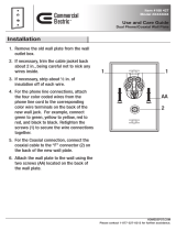
Installation
1 Never install telephone wiring during a lightning storm.
2 Never install telephone jacks in wet locations unless the jack is specifically designed for wet
locations.
3 Never touch uninsulated telephone wires or terminals unless the telephone line has been
disconnected at the network interface.
4 Use caution when installing or modifying telephone lines. The exclamation point within an
equilateral triangle is intended to alert the user to the presence of important operating and
maintenance (servicing) instructions in the literature accompanying the product.
This symbol on the product is used to identify the following important information: Use only
with a CSA or UL certified CLASS 2 level C power supply, as specified in the user guide.
Note: This equipment has been tested and found to comply with the limits for a
Class A digital device, pursuant to Part 15 of the FCC Rules. These limits are
designed to provide reasonable protection against harmful interference in a
residential installation. This equipment generates, uses and can radiate radio
frequency energy and, if not installed and used in accordance with the
instructions, may cause harmful interference to radio communications. However,
there is no guarantee that interference will not occur in a particular installation. If
this equipment does cause harmful interference to radio or television reception,
which can be determined by turning the equipment off and on, the user is
encouraged to try to correct the interference by one or more of the following
measures:
Warning: To avoid electrical shock hazard to personnel or equipment damage, observe
the following precautions when installing telephone equipment:

10
P0607659 02
Use
When using your telephone equipment, basic safety precautions should always be followed to
reduce risk of fire, electric shock and injury to persons, including the following:
1 Read and understand all instructions.
2 Follow the instructions marked on the product.
3 Unplug this product from the wall outlet before cleaning. Do not use liquid cleaners or aerosol
cleaners. Use a damp cloth for cleaning.
4 Do not use this product near water, for example, near a bath tub, wash bowl, kitchen sink, or
laundry tub, in a wet basement, or near a swimming pool.
5 Do not place this product on an unstable cart, stand or table. The product may fall, causing
serious damage to the product.
6 This product should never be placed near or over a radiator or heat register. This product
should not be placed in a built-in installation unless proper ventilation is provided.
7 Do not allow anything to rest on the power cord. Do not locate this product where the cord will
be abused by persons walking on it.
8 Do not overload wall outlets and extension cords as this can result in the risk of fire or electric
shock.
9 Never spill liquid of any kind on the product.
10 To reduce the risk of electric shock do not disassemble this product, but have it sent to a
qualified service person when some service or repair work is required.
11 Unplug this product from the wall outlet and refer servicing to qualified service personnel
under the following conditions:
a When the power supply cord or plug is damaged or frayed.
b If the product has been exposed to rain, water or liquid has been spilled on the product,
disconnect and allow the product to dry out to see if it still operates; but do not open up the
product.
c If the product housing has been damaged.
d If the product exhibits a distinct change in performance.
12 Avoid using a telephone during an electrical storm. There may be a remote risk of electric
shock from lightning.
13 Do not use the telephone to report a gas leak in the vicinity of the leak.
14 Caution: To eliminate the possibility of accidental damage to cords, plugs, jacks, and the
telephone, do not use sharp instruments during the assembly procedures.
15 Warning: Do not insert the plug at the free end of the handset cord directly into a wall or
baseboard jack. Such misuse can result in unsafe sound levels or possible damage to the
handset.
16 Save these instructions.

11
Installation and Maintenance Guide
International Regulatory Information
This is a class A product. In a domestic environment this product may cause radio interference in
which case the user may be required to take adequate measures.
Hereby, Nortel Networks declares that Enterprise Edge/Business Communications Manager
Model No. NT7B10xxxx, is in compliance with the essential requirements and other relevant
provisions of Directive 1999/5/EC.
Information is subject to change without notice. Nortel Networks reserves the right to make
changes in design or components as progress in engineering and manufacturing may warrant. This
equipment has been tested and found to comply with the European Safety requirements EN 60950
and EMC requirements EN 55022 (Class A) and EN 55024. These EMC limits are designed to
provide reasonable protection against harmful interference when the equipment is operated in a
commercial and light industrial environment.
Safety
The CE Marking on this equipment indicates compliance with
the following:
This device conforms to Directive 1999/5/EC on Radio
Equipment and Telecommunications Terminal Equipment as
adopted by the European Parliament And Of The Council.
WARNING
This is a class A product. In a domestic environment this product may cause radio
interference in which case the user may be required to take adequate measures. The
above warning is inserted for regulatory reasons. If any customer believes that they have
an interference problem, either because their Nortel Networks product seems to cause
interference or suffers from interference, they should contact their distributor immediately.
The distributor will assist with a remedy for any problems and, if necessary, will have full
support from Nortel Networks.
WARNING!
Only qualified service personnel may install this equipment. The instructions in this
manual are intended for use by qualified service personnel only.
Risk of shock.
Ensure the Business Communications Manager base unit is unplugged from the power
socket and that any telephone or network cables are unplugged before opening the
Business Communications Manager base unit.
Read and follow installation instructions carefully

12
P0607659 02
Only qualified persons should service the system.
The installation and service of this hardware is to be performed only by service personnel
having appropriate training and experience necessary to be aware of hazards to which
they are exposed in performing a task and of measures to minimize the danger to
themselves or other persons.
Electrical shock hazards from the telecommunication network and AC mains are possible
with this equipment. To minimize risk to service personnel and users, the Business
Communications Manager system must be connected to an outlet with a third-wire Earth.
Service personnel must be alert to the possibility of high leakage currents becoming
available on metal system surfaces during power line fault events near network lines.
These leakage currents normally safely flow to Protective Earth via the power cord.
Therefore, it is mandatory that connection to an earthed outlet is performed first and
removed last when cabling to the unit. Specifically, operations requiring the unit to be
powered down must have the network connections (exchange lines) removed first.

13
Installation and Maintenance Guide
Additional Safety Information
The following interfaces are classified as Telecommunication Network Voltage (TNV) circuits,
and may be connected to exposed plant:
• DTM interface
• WAN interface
• TCM Isolator
The following interfaces are classified as Safety Extra Low Voltage (SELV) circuits, and shall not
be connected to exposed plant:
•BRIM Interface
• TCM extensions
• external music sources (MSCX)
• auxiliary ringer (AUX)
• paging system relay (PAGE)
• serial port
• LAN interface
The following interfaces are classified as Telecommunication Network Voltage (TNV) circuits,
and shall NOT be connected to exposed plant:
•ATA II
Limited Warranty
Nortel Networks warrants this product against defects and malfunctions during a one (1) year
period from the date of original purchase. If there is a defect or malfunction, Nortel Networks
shall, at its option, and as the exclusive remedy, either repair or replace the telephone set at no
charge, if returned within the warranty period.
If replacement parts are used in making repairs, these parts may be refurbished, or may contain
refurbished materials. If it is necessary to replace the telephone set, it may be replaced with a
refurbished telephone of the same design and color. If it should become necessary to repair or
replace a defective or malfunctioning telephone set under this warranty, the provisions of this
warranty shall apply to the repaired or replaced telephone set until the expiration of ninety (90)
days from the date of pick up, or the date of shipment to you, of the repaired or replacement set, or
until the end of the original warranty period, whichever is later. Proof of the original purchase date
is to be provided with all telephone sets returned for warranty repairs.
Exclusions
Nortel Networks does not warrant its telephone sets to be compatible with the equipment of any
particular telephone company. This warranty does not extend to damage to products resulting from
improper installation or operation, alteration, accident, neglect, abuse, misuse, fire or natural
causes such as storms or floods, after the telephone is in your possession.

14
P0607659 02
Nortel Networks shall not be liable for any incidental or consequential damages, including, but not
limited to, loss, damage or expense directly or indirectly arising from the customers use of or
inability to use this telephone, either separately or in combination with other equipment. This
paragraph, however, shall not apply to consequential damages for injury to the person in the case
of telephones used or bought for use primarily for personal, family or household purposes.
This warranty sets forth the entire liability and obligations of Nortel Networks with respect to
breach of warranty, and the warranties set forth or limited herein are the sole warranties and are in
lieu of all other warranties, expressed or implied, including warranties or fitness for particular
purpose and merchantability.
Warranty Repair Services
Should the set fail during the warranty period:
In North America, please call 1-800-574-1611 for further information.
Outside North America, contact your sales representative for return instructions. You will be
responsible for shipping charges, if any. When you return this telephone for warranty service, you
must present proof of purchase.
After Warranty Service
Nortel Networks offers ongoing repair and support for this product. This service provides repair or
replacement of your Nortel Networks product, at Nortel Networks option, for a fixed charge. You
are responsible for all shipping charges. For further information and shipping instructions:
In North America, contact our service information number: 1-800-574-1611.
Outside North America, contact your sales representative.
Repairs to this product may be made only by the manufacturer and its authorized agents, or by
others who are legally authorized. This restriction applies during and after the warranty period.
Unauthorized repair will void the warranty.

Functional changes, 3.5 software
Business Communications Manager 3.5
changes affecting the BCM1000
BCM 3.5 program updates
This document provides supplemental information for the BCM 3.5 software release
for systems using BCM1000 hardware that has been upgraded from earlier versions of
the Business Communications Manager software.
This includes:
• Security changes on page 15
• New hardware on page 16
• Market profile changes on page 23
Security changes
Business Communications Manager 3.5 introduces a number of security
enhancements with the addition of a security layer to the programing. One change that
particularly affects maintenance procedures is the shift from the Telnet interface to
using a secure interface (SSH-based) to access the text-based Unified Manager menus
from a computer connecting to the Business Communications Manager over a LAN,
for instance when you want to initialize a new hard disk. Connecting to the BCM1000
through a serial or crossover cable configuration is not affected by this change.
If your company wishes to continue using Telnet over the LAN or if you have DECT
equipment, the Telnet service can be manually enabled through the Unified Manager,
under Services. If you have DECT equipment, Telnet is required to run the DECT
programming.
The client SSH application is called PuTTY. A link to download this application to
your desktop can be found under the Install Clients button on the first page of the
Unified Manager. The application installs on your computer, not on the Business
Communications Manager. Therefore, if you want to use a LAN to connect to the
Business Communications Manager hardware during maintenance procedures, you
must install PuTTY on your computer before beginning any procedures that require
you to access the text-based interface.
As well, the connection to the Unified Manager is now through an https// link rather
than
http//. To log on to the Unified Manager you enter: https//<BCM IP address> on your
browser. Any existing bookmarks will automatically convert to https// during the
connection process.

16 BCM1000, BCM 3.5 addendum
BCM1000 Installation and Maintenance Guide P0607659 02
New hardware
This section describes the new hardware that was released in conjunction with the BCM 3.5 software
release.
This includes:
• Global Analog Trunk Module (GATM) on page 16
•
Auxiliary equipment on page 21
Global Analog Trunk Module (GATM)
The following table demonstrates who the GATM fits into the Business Communications Manager trunk
module suite.
The Global Analog Trunk Module (GATM) provides an interface to the telephone company analog lines
for the Business Communication Manager. The module supports both pulse and tone dialing, Caller ID,
and Supervision Disconnect in various markets.
UK profile configuration note: The GATM does not support Earth Calling even though the option appears
in the Unified Manager Lines record. Only a FEM connected to a Norstar analog trunk module supports
this feature.
Table 1 Global Analog Trunk Module notes
Trunk module type What it does Special notes
DTM
Digital Trunk media bay
module on page 94
Connects digital public switched
telephone lines to the Business
Communications Manager system.
Can connect to four types of lines: TI,
NA PRI, ETSI (in UK only), and Euro PRI.
CTM
Caller ID Trunk media bay
module on page 95
CTM8
Caller ID Trunk media bay
module on page 95
Connects a maximum of four analog
public switched telephone lines to the
Business Communications Manager
system.
Connects a maximum of eight analog
public switched telephone lines to the
Business Communications Manager
system.
Only available for North American systems.
See also
4X16 media bay module on
page 99.
BRI
Basic Rate Interface media
bay module on page 96
Connects a maximum of four ISDN BRI
interfaces
Note: The DECT module contains the
equivalent of a BRI module and does not
require a separate module for trunk line
functions.
GATM (Global Analog Trunk
Module
Connects either four (GATM4) or eight
(GATM8) analog public switched
telephone lines to the Business
Communications Manager system.
Only North America, Taiwan, UK and
Australia are supported. Modules installed
in BCM 3.5 systems can be set to
automatically download firmware from the
Business Communications Manager. This
allows for firmware updates, as required.

BCM1000, BCM 3.5 addendum 17
P0607659 02 BCM1000 Installation and Maintenance Guide
The figure below shows the front of the GATM module. Note that both the GATM4 and the GATM8 have
only one amphenol connector. The firmware differentiates how many lines the connector supports.
There are two models of GATM:
GATM 4: The GATM4 provides connections for four analog calling line identification (CLID) or
Supervision Disconnect PSTN lines. Each voice line uses one line in the DS30 bus offset. Since each
DS30 channel has four lines per offset, you can assign a maximum of four GATM4s to a single DS30 bus
by making the offset switch settings different for each module.
GATM 8: The GATM 8 provides connections for eight analog calling line identification (CLID) or
Supervision Disconnect PSTN lines. Each line uses one line in the DS30 bus offset. Since each DS30 bus
has four lines per offset, you require two offsets for each GATM8. You can assign a maximum of two
GATM8s to a DS30 bus, by making the offset switch settings different for each module. You can also
combine a GATM 8 with a 4X16 module on the same DS30 number. When you choose an offset number
for the GATM 8, the system automatically adds the next offset number. You cannot assign offset 3 to the
GATM 8 module, because this does not allow the module to assign the second set of lines.
The following figure graphically shows how you can allocate the GATM modules over a DS30 bus.
Power LED
Status LED
Amphenol
connector
4 GATMs
GATM8s
per DS30
channel
One DS30 Bus/
offset 0, 1, 2, or 3
One DS30 Bus/
offset set to 0, 1, or 2
per DS30
channel
max. of
2 offsets
2 GATM4s
Combined allocation
over one DS30 Bus
1 GATM8
1 GATM8 (offset 0)
Combined allocation with 4X16
using two DS30 buses
1 4X16 module
(offset 0 and 1)
(offset 2)
(offset 3 on the
(offset 2 is empty)
first DS30 bus)
(a maximum of
two GATM8s per bus)

18 BCM1000, BCM 3.5 addendum
BCM1000 Installation and Maintenance Guide P0607659 02
GATM switch settings
There are two sets of DIP switches located on the rear of the GATM module. The left set allows you to
determine the DS30 bus and offset for the module.
The right set of switches allows you to manually configure a country profile operation, which is required
for earlier versions of software. However, BCM 3.5 software supports downloadable firmware for the
module for the North America, Taiwan, UK and Australia telephone profiles. To allow the GATM to
download the parameters for these countries and to allow for firmware upgrades, set all the country DIP
switches to 0 (zero/off) (factory default). The MSC telephony profile you choose must support the
appropriate country setting to ensure that the correct firmware installs.
The table below lists the possible DIP switch settings for the Mode and Country DIP switches.
Table 2 Global Analog Trunk Module DIP switch settings
Mode select DIP switch settings
Country select DIP switch settings
DS30
bus #
Offsets Offset positions DIP switch settings
GATM4
Offsets
0, 1, 2, 3
GATM8
Offsets
0, 1, 2
12 3
(offset)
45 6
(DS30 #)
2
0 0 0 on on on on on on
12 3 456 7 8
Switch Function
1 1 1 on on off on on on Reserved
2 2 2 on off on on on on Reserved
3 3 on off off on on on Reserved
3
0 0 0 on on on on on off Reserved
1 1 1 on on off on on off Reserved
2 2 2 on off on on on off Country 3
3 3 on off off on on off Country 2
4
0 0 0 on on on on off on Country 1
1 1 1 on on off on off on
2 2 2 on off on on off on Setting for automatic downloads (all countries)
3 3 on off off on off on off off off off off off off off Download based on profile
5
0 0 0 on on on on off off Manual settings (pre-BCM 3.5 systems)
1 1 1 on on off on off off off off off off off off off on North America (600 ohms)
2 2 2 on off on on off off off off off off off off on off Taiwan
3 3 on off off on off off off off off off off off on on Australia
6
0 0 0 on on on off on on off off off off off on off off United Kingdom
1 1 1 on on off off on on off off off off off on off on North America (900 ohms)
2 2 2 on off on off on on
3 3 on off off off on on
1 2 3 4 5 6
ON
Mode select
Country select
ON
1 2 3 4 5 6 7 8
Rear of GATM
For BCM 3.5 software,
ensure all switches
are off

BCM1000, BCM 3.5 addendum 19
P0607659 02 BCM1000 Installation and Maintenance Guide
Wiring the GATM
The other trunk media bay modules are connected using RJ-type jacks. The GATM, however, uses an
amphenol connector. These cables can be supplied by qualified technical personnel to ensure the correct
pin-out.
To connect the Global analog trunk module (GATM) to the network, follow these steps:
1. On the front of the module, locate the amphenol connector.
2 Wire one end of the cable to the telco demarcation blocks of the building.
3 Wire the other end of the cable to the analog lines. Refer to the figure and table on the next page.
7
0 0 0 on on on off on off
1 1 1 on on off off on off
2 2 2 on off on off on off
3
3onoff off off on off
Warning: Use only qualified persons to service the system.
The installation and service of this unit must be performed by service personnel with the appropriate
training and experience. Service personnel must be aware of the hazards of working with telephony
equipment and wiring. They must have experience in techniques that minimize any danger of shock or
equipment damage.
Warning: Leakage currents
Service personnel must be alert to the possibility of high leakage currents becoming available on metal
system surfaces during power line fault events on network lines. These leakage currents normally safely
flow to Protective Earth ground via the power cord. However, if the ac power is unplugged prior to
disconnecting the cables from the front of the base unit, this hazard can occur.
System shutdown: You must disconnect the media bay module cables from the system before
disconnecting the power cord from a grounded outlet.
System startup: You must reconnect the power cords to an grounded outlet before reconnecting the
cables to the media bay modules.
Danger: Electrical shock hazards
Electrical shock hazards from the telecommunications network and ac mains are possible with this
equipment. To minimize risk to service personnel and users, the Business Communications Manager
system must be connected to an outlet with a third wire ground.
In addition, all unused slots must have blank faceplates installed. The covers on all units must be in
place at the completion of any servicing.
Table 2 Global Analog Trunk Module DIP switch settings

20 BCM1000, BCM 3.5 addendum
BCM1000 Installation and Maintenance Guide P0607659 02
The following figure and table show the wiring pin outs for a GATM to connect to a service provider.
Connector pinout Line Pin Wire color GATM module
1 26 White-Blue Both
1 Blue-White
2 27 White-Orange Both
2 Orange-White
No
connectio
n
28/3
29/4
3 30 White-Slate Both
5 Slate-White
4 31 Red-Blue Both
6 Blue-Red
No
connectio
n
32/7
33/8
5 34 Red-Brown GATM8
9Brown-Red
6 35 Red-Slate GATM8
10 Slate-Red
No
connectio
n
36/11
37/12
7 38 Black-Green GATM8
13 Green-Black
8 39 Black-Brown GATM8
14 Brown-Black
No
connectio
n
40/15 to
49/24
Aux 50 Violet-Slate Both
25 Slate-Violet
* Auxiliary port function: In download mode, the auxiliary port function for all profiles operates as a true Auxiliary
port. This means that when the power comes back on, and if the Aux Port is in-use, that line will show on the
system telephones as being in-use (LCD indicator lit) until the Aux Call is cleared.
In dipswitch mode, the North American and Taiwan auxiliary ports also act as true auxiliary ports.
However, the UK and Australia profile auxiliary port function is different. In these profiles, when the power is
restored, the Aux Port call is terminated and the line is available to system telephones.
8R
7R
6R
5R
4R
3R
2R
1 R
9R
10R
11R
12R
13R
14R
15R
16R
33T
32T
31T
30T
29T
28T
27T
26 T
34T
35T
36T
37T
38T
39T
40T
41T
17R
42T
18R
43T
19R
44T
20R
45T
21R
46T
22R
47T
23R
48T
24R
49T
25R
50T
*AUX
Line 1
Line 2
Line 3
Line 4
Line 5
Line 6
Line 7
Line 8
/