
NP951-B16C
System Board
User’s Manual
A11030124

Copyright
This publication contains information that is protected by copyright. No part of it
may be reproduced in any form or by any means or used to make any transfor-
mation/adaptation without the prior written permission from the copyright hold-
ers.
This publication is provided for informational purposes only. The manufacturer
makes no representations or warranties with respect to the contents or use
of this manual and specifically disclaims any express or implied warranties of
merchantability or fitness for any particular purpose. The user will assume the
entire risk of the use or the results of the use of this document. Further, the
manufacturer reserves the right to revise this publication and make changes to
its contents at any time, without obligation to notify any person or entity of such
revisions or changes.
© 2011. All Rights Reserved.
Trademarks
Windows
®
2000 and Windows
®
XP are registered trademarks of Microsoft Corpo-
ration. Award is a registered trademark of Award Software, Inc. Other trademarks
and registered trademarks of products appearing in this manual are the proper-
ties of their respective holders.

FCC and DOC Statement on Class B
This equipment has been tested and found to comply with the limits for a Class B
digital device, pursuant to Part 15 of the FCC rules. These limits are designed to
provide reasonable protection against harmful interference when the equipment
is operated in a residential installation. This equipment generates, uses and can
radiate radio frequency energy and, if not installed and used in accordance with
the instruction manual, may cause harmful interference to radio communications.
However, there is no guarantee that interference will not occur in a particular
installation. If this equipment does cause harmful interference to radio or televi-
sion reception, which can be determined by turning the equipment off and on,
the user is encouraged to try to correct the interference by one or more of the
following measures:
• Reorientorrelocatethereceivingantenna.
• Increasetheseparationbetweentheequipmentandthereceiver.
• Connecttheequipmentintoanoutletonacircuitdifferentfromthattowhich
the receiver is connected.
• ConsultthedealeroranexperiencedradioTVtechnicianforhelp.
Notice:
1. The changes or modifications not expressly approved by the party responsible
for compliance could void the user’s authority to operate the equipment.
2. Shielded interface cables must be used in order to comply with the emission
limits.

1
4
Introduction
Table of Contents
Copyright ...........................................................................................2
Trademarks ........................................................................................2
FCC and DOC Statement on Class B ..............................................3
About this Manual .............................................................................7
Warranty ..........................................................................................7
Static Electricity Precautions .............................................................8
Safety Measures .................................................................................8
About the Package ............................................................................9
Before Using the System Board ........................................................9
Chapter 1 - Introduction ................................................................10
Specifications ................................................................................ 10
Features ...................................................................................... 12
Chapter 2 - Hardware Installation .................................................. 15
System Board Layout .................................................................... 15
System Memory ...........................................................................17
Installing the DIM Module
......................................................... 18
Jumper Settings ............................................................................. 20
Clear CMOS Data
..................................................................... 20
PS/2 Power Select
.................................................................... 21
USB Power Select
..................................................................... 22
Panel Power Select
................................................................... 23
COM 2 RS232/RS422/RS485 Select
............................................ 24
COM 1 RS232/Power Select
....................................................... 25
Power-on Select
....................................................................... 26
Rear Panel I/O Ports .....................................................................27
DC-in 12V / Optional 4-pin ATX 12V Power
................................. 28
USB Ports................................................................................ 29
LAN Port
................................................................................. 31
VGA Port
................................................................................. 32
COM (Serial) Ports
................................................................... 33
PS/2 Port
................................................................................ 34

1
5
Introduction
I/O Connectors ............................................................................ 35
S/PDIF Connector
..................................................................... 35
LVDS LCD Panel Connector and LCD/Inverter Power Connector
...... 36
Digital I/O Connector
................................................................ 38
SATA (Serial ATA) Connectors
.................................................... 39
Cooling Fan Connector
.............................................................. 40
Front Audio Connector
.............................................................. 41
Front Panel Connector
.............................................................. 42
Expansion Slot
......................................................................... 43
Battery
................................................................................... 44
CompactFlash Socket
................................................................ 45
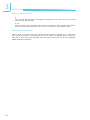
Chapter 3 - BIOS Setup .................................................................. 46
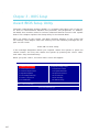
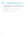
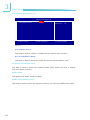
Award BIOS Setup Utility .............................................................. 46
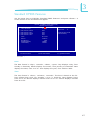
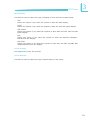
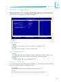
Standard CMOS Features
..........................................................47
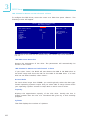
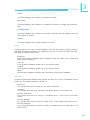
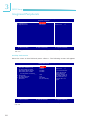
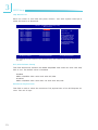
Advanced BIOS Features
........................................................... 51
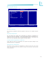
Advanced Chipset Features
........................................................ 56
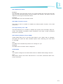
Integrated Peripherals
.............................................................. 60
Power Management Setup
......................................................... 68
PnP/PCI Configurations
............................................................. 71
PC Health Status
...................................................................... 73
Frequency/Voltage Control
........................................................ 75
Load Fail-Safe Defaults
............................................................. 76
Load Optimized Defaults
........................................................... 77
Set Supervisor Password
........................................................... 78
Set User Password
................................................................... 79
Save & Exit Setup
.................................................................... 80
Exit Without Saving
.................................................................. 81
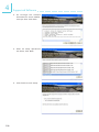
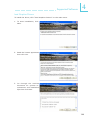
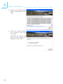
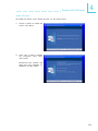
Updating the BIOS ........................................................................ 82
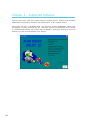
Chapter 4 - Supported Software ................................................... 84
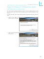
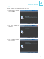
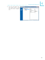
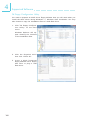
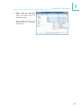
Drivers for Windows 7 / Windows Vista System................................. 85
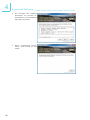
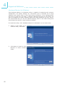
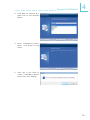
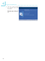
Intel Chipset Software Installation Utility
.................................... 85
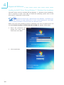
Intel Graphics Drivers
............................................................... 87
Audio Drivers
........................................................................... 90
LAN Drivers
............................................................................. 91
Hardware Monitor for Windows
.................................................. 92
Intel Matrix Storage Manager Utility
........................................... 97
F6 Floppy Configuration Utility
................................................. 100
Installing the AHCI Driver During Windows 7 / Windows Vista
Installation
............................................................................ 102
Adobe Acrobat Reader 7.0 (English Version)
.............................. 106
Drivers for Windows XP System ................................................. 107
Intel Chipset Software Installation Utility
.................................. 107
Intel Graphics Drivers
............................................................. 109
Audio Drivers
......................................................................... 111
LAN Drivers
........................................................................... 112
Hardware Monitor for Windows
................................................ 113
Intel Matrix Storage Manager Utility
......................................... 115
F6 Floppy Configuration Utility
................................................. 117

1
6
Introduction
Installing the AHCI Driver During Windows XP Installation .......... 118
Microsoft DirectX 9.0C Driver
.................................................. 119
Adobe Acrobat Reader 7.0 (English Version)
.............................. 120
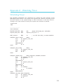
Appendix A - Watchdog Timer...................................................... 121
Appendix B - System Error Message ............................................ 124
Appendix C - Troubleshooting ...................................................... 126

1
7
Introduction
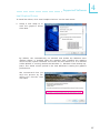
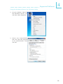
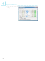
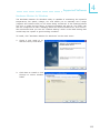
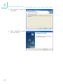
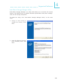
About this Manual
An electronic file of this manual is included in the CD. To view the user’s manual
in the CD, insert the CD into a CD-ROM drive. The autorun screen (Main Board
Utility CD) will appear. Click “User’s Manual” on the main menu.
Warranty
1. Warranty does not cover damages or failures that arised from misuse of the
product, inability to use the product, unauthorized replacement or alteration
of components and product specifications.
2. The warranty is void if the product has been subjected to physical abuse,
improper installation, modification, accidents or unauthorized repair of the
product.
3. Unless otherwise instructed in this user’s manual, the user may not, under
any circumstances, attempt to perform service, adjustments or repairs on the
product, whether in or out of warranty. It must be returned to the purchase
point, factory or authorized service agency for all such work.
4. We will not be liable for any indirect, special, incidental or consequencial
damages to the product that has been modified or altered.

1
8
Introduction
Static Electricity Precautions
It is quite easy to inadvertently damage your PC, system board, components
or devices even before installing them in your system unit. Static electrical dis-
charge can damage computer components without causing any signs of physical
damage. You must take extra care in handling them to ensure against electro-
static build-up.
1. To prevent electrostatic build-up, leave the system board in its anti-static bag
until you are ready to install it.
2. Wear an antistatic wrist strap.
3. Do all preparation work on a static-free surface.
4. Hold the device only by its edges. Be careful not to touch any of the compo-
nents, contacts or connections.
5. Avoid touching the pins or contacts on all modules and connectors. Hold
modules or connectors by their ends.
Important:
Electrostatic discharge (ESD) can damage your processor, disk drive and
other components. Perform the upgrade instruction procedures described
at an ESD workstation only. If such a station is not available, you can
provide some ESD protection by wearing an antistatic wrist strap and
attaching it to a metal part of the system chassis. If a wrist strap is
unavailable, establish and maintain contact with the system chassis
throughout any procedures requiring ESD protection.
Safety Measures
To avoid damage to the system:
• UsethecorrectACinputvoltagerange.
To reduce the risk of electric shock:
• Unplug the power cord before removing the system chassis cover for instal-
lation or servicing. After installation or servicing, cover the system chassis
before plugging the power cord.
Battery:
• Dangerofexplosionifbatteryincorrectlyreplaced.
• Replace only with the same or equivalent type recommend by the manufac-
turer.
• Disposeofusedbatteriesaccordingtolocalordinance.

1
9
Introduction
About the Package
The system board package contains the following items. If any of these items are
missing or damaged, please contact your dealer or sales representative for as-
sistance.
One system board
One USB cable
One Serial ATA data cable
One Serial ATA power cable
One COM port cable
One PS/2 KB/Mouse cable
One user’s manual
One CD
One QR (Quick Reference)
The system board and accessories in the package may not come similar to the
information listed above. This may differ in accordance to the sales region or
models in which it was sold. For more information about the standard package in
your region, please contact your dealer or sales representative.
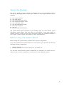
Before Using the System Board
Before using the system board, prepare basic system components.
If you are installing the system board in a new system, you will need at least the
following internal components.
• Memorymodule
• Storagedevicessuchasharddiskdrive,CD-ROM,etc.
You will also need external system peripherals you intend to use which will nor-
mally include at least a keyboard, a mouse and a video display monitor.

1
10
Introduction
Processor
Chipset
System Memory
Expansion Slots
Graphics
Audio
LAN
Serial ATA
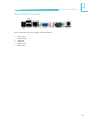
Rear Panel I/O
Ports
Chapter 1 - Introduction
•Intel
®
Atom
TM
N270 processor
•1.6GHzcorefrequency,1.10Vvoltage
•2.5Wthermaldesignpower
•512KBon-diesecondlevelcache
•533MHzFSB
•22x22mm,1.0mmballpitchand437ballsFCBGA
•Intel
®
chipset
-Intel
®
945GSEGraphicMemoryControllerHub(GMCH)
-Intel
®
ICH7MI/OControllerHub
•One200-pinSODIMMsocket(1.8V)
•SupportsDDR400/533MHz
•Supportsupto2GBsystemmemory
•1miniPCIslot
•1CompactFlashsocket
•Intel
®
GMA950
•133/166MHz internal graphics core render frequency at
1.05Vcorevoltage
•Supports18-bitdual-channelLVDS
•VGAdisplayresolutionuptoSXGA+1400x1050
•RealtekALC262HighDefinitionAudio
•Two24-bitstereoDACsandthree20-bitstereoADCs
•S/PDIFaudiointerface
•One Realtek RTL8111C PCI Express Gigabit Ethernet con-
troller
•Supports10Mbps,100Mbpsand1Gbpsdatatransmission
•IEEE 802.3 (10/100Mbps) and IEEE 802.3ab (1Gbps) com-
pliant
•One Serial ATA interface supported which is compliant with
SATA1.0specification(1.5Gbpsinterface)
•Two-mode operation supports legacy mode using I/O space
oranAHCImodeusingmemoryspace
•SATA and PATA can be used in a combined function mode
(When SATA is used with PATA, AHCI mode is not support-
ed.)
•1mini-DIN-6portforPS/2mouseandPS/2keyboardports
•1DC-in12Vjackor4-pinATX12Vpowerconnector
(optional)
•1DB-9RS232serialport
- Pins 1 and 9 functions as RS232 signal or power (select-
ableviajumper)
•1DB-15VGAport
•1RJ45LANport
•2USB2.0/1.1ports
Specifications

1
11
Introduction
I/O Connectors
BIOS
Energy Efficient
Design
Damage Free
Intelligence
Temperature
Humidity
PCB
•2connectorsfor4externalUSB2.0/1.1ports
•1connectorforanexternalRS232/422/485serialport
•1LVDSLCDpanelconnector
•1LCD/inverterpowerconnector
•18-bitDigitalI/Oconnector
•1frontaudioconnectorforline-outandmic-injacks
•1S/PDIFconnector
•1SerialATAconnector
•14-pinpowerconnectorforSATAdrive
•1frontpanelconnector
•1fanconnector
•AwardBIOS
•8MbitSPIBIOS
•ACPI2.0/1.0specification
•Wake-On-Eventsinclude:
- Wake-On-PS/2Keyboard/Mouse
- WakeupbyminiPCIcard
- Wake-On-LAN
- USBKB/MSwakeupfromS3
- Wake-On-Ring
- RTCtimertopower-onthesystem
•EnhancedIntel
®
SpeedStepTechnology
•ACpowerfailurerecovery
•MonitorsCPU/systemtemperatureandoverheatalarm
•Monitors CPU(V)/3.3V/5V/12V/VBAT(V) voltages and failure
alarm
•MonitorsCPUfanspeedandfailurealarm
•Readbackcapabilitythatdisplays temperature,voltageand
fan speed
•Watchdogtimerfunction
•0
o
Cto60
o
C
•10%to90%
•102mm(4.02”)x147mm(5.79”)

1
12
Introduction
Features
Watchdog Timer
The Watchdog Timer function allows your application to regularly “clear” the sys-
tem at the set time interval. If the system hangs or fails to function, it will reset
at the set time interval so that your system will continue to operate.
CompactFlash
The system board is equipped with the CompactFlash
TM
socket for inserting a
CompactFlash
TM
card. CompactFlash
TM
card is a small removable mass storage
device designed with flash technology - a non-volatile storage solution that does
not require a battery to retain data indefinitely. The CompactFlash
TM
technology
is widely used in products such as portable and desktop computers, digital cam-
eras, handheld data collection scanners, PDAs, Pocket PCs, handy terminals and
personal communicators.
DDR2
DDR2 is a higher performance DDR technology whose data transfer rate delivers
bandwidth of 4.3 GB per second and beyond. That is twice the speed of the con-
ventional DDR without increasing its power consumption. DDR2 SDRAM modules
work at 1.8V supply compared to 2.6V memory voltage for DDR modules. DDR2
also incorporates new innovations such as the On-Die Termination (ODT) as well
as larger 4-bit pre-fetch against DDR which fetches 2 bits per clock cycle.
Graphics
The Intel
®
945GSE Express Chipset features an integrated 32-bit 3D graphics en-
gine based on the Intel
®
Graphics Media Accelerator 950 architecture; delivering
sophisticated graphics for large display applications. Graphics interfaces such as
VGAanddual-channelLVDSsupportmultiplegraphicsdisplayoptions.
S/PDIF
S/PDIF is a standard audio file transfer format that transfers digital audio sig-
nals to a device without having to be converted first to an analog format. This
prevents the quality of the audio signal from degrading whenever it is converted
to analog. S/PDIF is usually found on digital audio equipment such as a DAT
machine or audio processing device. The S/PDIF connector on the system board
sends surround sound and 3D audio signal outputs to amplifiers and speakers
and to digital recording devices like CD recorders.
Serial ATA
Serial ATA is a storage interface that is compliant with SATA 1.0a specification.
With speed of up to 150MB/s, it improves hard drive performance faster than the
standard parallel ATA whose data transfer rate is 100MB/s.

1
13
Introduction
Gigabit LAN
The Realtek RTL8111C PCI Express Gigabit controller supports up to 1Gbps data
transmission.
USB
The system board supports USB 2.0 and USB 1.1 ports. USB 1.1 supports 12Mb/
second bandwidth while USB 2.0 supports 480Mb/second bandwidth providing a
marked improvement in device transfer speeds between your computer and a
wide range of simultaneously accessible external Plug and Play peripherals.
Wake-On-Ring
This feature allows the system that is in the Suspend mode or Soft Power Off
mode to wake-up/power-on to respond to calls coming from an external modem
or respond to calls from a modem PCI card that uses the PCI PME (Power Man-
agement Event) signal to remotely wake up the PC.
Important:
The 5V_standby power source of your power supply must support
≥720mA.
Wake-On-LAN
This feature allows the network to remotely wake up a Soft Power Down (Soft-
Off) PC. It is supported via the onboard LAN port or via a PCI LAN card that uses
the PCI PME (Power Management Event) signal. However, if your system is in the
Suspend mode, you can power-on the system only through an IRQ or DMA inter-
rupt.
Important:
The 5V_standby power source of your power supply must support
≥720mA.
Wake-On-PS/2
This function allows you to use the PS/2 keyboard or PS/2 mouse to power-on
the system.
Important:
The 5V_standby power source of your power supply must support
≥720mA.

1
14
Introduction
Wake-On-USB
This function allows you to use a USB keyboard or USB mouse to wake up a sys-
tem from the S3 (STR - Suspend To RAM) state.
Important:
If you are using the Wake-On-USB Keyboard/Mouse function for 2 USB
ports, the 5V_standby power source of your power supply must support
≥1.5A. For 3 or more USB ports, the 5V_standby power source of your
power supply must support ≥2A.
RTC Timer
The RTC installed on the system board allows your system to automatically pow-
er-on on the set date and time.
ACPI STR
The system board is designed to meet the ACPI (Advanced Configuration and
Power Interface) specification. ACPI has energy saving features that enables PCs
to implement Power Management and Plug-and-Play with operating systems that
support OS Direct Power Management. ACPI when enabled in the Power Manage-
ment Setup will allow you to use the Suspend to RAM function.
With the Suspend to RAM function enabled, you can power-off the system at
once by pressing the power button or selecting “Standby” when you shut down
Windows
®
without having to go through the sometimes tiresome process of
closing files, applications and operating system. This is because the system is
capable of storing all programs and data files during the entire operating session
into RAM (Random Access Memory) when it powers-off. The operating session will
resume exactly where you left off the next time you power-on the system.
Power Failure Recovery
When power returns after an AC power failure, you may choose to either power-
on the system manually or let the system power-on automatically.

15
2
Hardware Installation
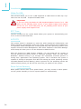
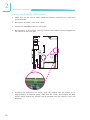
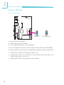
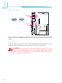
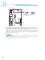
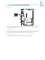
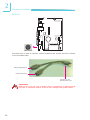
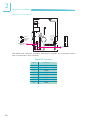
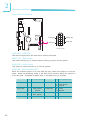
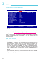
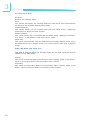
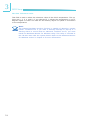
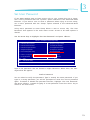
System Board Layout
Chapter 2 - Hardware Installation
1
LCD/Inverter
power
VGA
COM 1
LAN
USB 0
USB 1
DC-IN 12V
SPI Flash BIOS
1
Clear CMOS
(JP6)
1
CPU fan
CompactFlash
LVDS LCD panel
1
1
COM1power
select (JP2)
Chassis intrusion
COM 2
422/485 select (JP9)
RS232/
1
Panel power
select (J8)
USB 2-3
1
USB 2-3 power
select (JP3)
1
SATA 1
Power-on
select (JP5)
USB 0-1 power
select (JP4)
Standby LED
PS/2
Front
audio
9
10
1
2
Realtek
RTL 8111C
PS/2 power
select (JP1)
DIO power
1
S/PDIF
1
DIO
Peripheral power
1
Battery
9
3
5
1
4039
2
1
2
910
1
2
3
4
5
6
1
1
Mini PCI
COM 2
1
2
910
1
2
3
4
5
6
1
DDR2 SODIMM
8
8
7
24
6
1
1
AT X +12V power (optional)
10 9
21
1
2
12 11
Front panel
USB 4-5
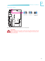
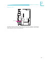
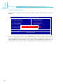
Component Side

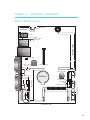
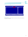
16
2
Hardware Installation
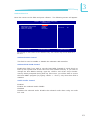
Solder Side
Realtek
ALC262
Intel
ICH7M
945GSE
Intel
Atom N270
Intel
Winbond
W83627

17
2
Hardware Installation
System Memory
Important:
Electrostatic discharge (ESD) can damage your system board, processor,
disk drives, add-in boards, and other components. Perform the upgrade
instruction procedures described at an ESD workstation only. If such a
station is not available, you can provide some ESD protection by wearing
an antistatic wrist strap and attaching it to a metal part of the system
chassis. If a wrist strap is unavailable, establish and maintain contact
with the system chassis throughout any procedures requiring ESD pro-
tection.
SODIMM
The system board is equipped with a 200-pin SODIMM socket that supports DDR2
module.
BIOS Setting
Congure the system memory in the Advanced Chipset Features submenu of the
BIOS.

18
2
Hardware Installation
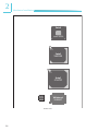
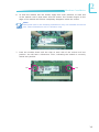
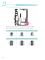
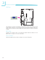
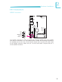
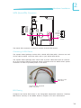
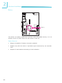
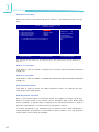
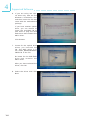
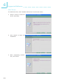
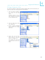
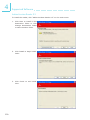
Installing the SODIMM DDR2 Module
1. Make sure the PC and all other peripheral devices connected to it has been
powered down.
2. Disconnect all power cords and cables.
3. Locate the SODIMM socket on the board.
4. Note the key on the socket. The key ensures the module can be plugged into
the socket in only one way.
5. Grasping the module by its edges, align the module into the socket at an
approximately 30 degrees angle. Note that the socket and module are both
keyed, which means the module can be plugged into the socket in only one
direction.

19
2
Hardware Installation
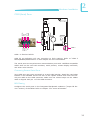
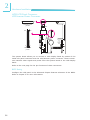
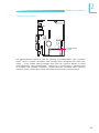
Clip
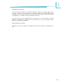
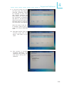
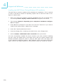
6. To seat the module into the socket, apply rm even pressure to each end
of the module until it slips down into the socket. The contact ngers on the
edge of the module will almost completely disappear inside the socket.
Note:
The board used in the following illustrations may not resemble the actual
one. These illustrations are for reference only.
7. Push the module down until the clips at each side of the socket lock into
position. You will hear a distinctive “click”, indicating the module is correctly
locked into position
Clip

20
2
Hardware Installation
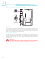
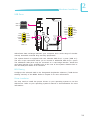
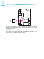
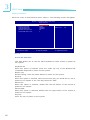
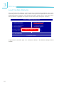
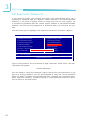
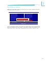
Jumper Settings
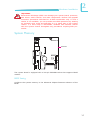
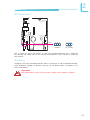
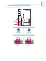
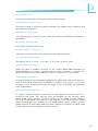
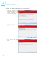
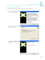
Clear CMOS Data
If you encounter the following,
a) CMOS data becomes corrupted.
b) You forgot the supervisor or user password.
you can recongure the system with the default values stored in the ROM BIOS.
To load the default values stored in the ROM BIOS, please follow the steps below.
1. Power-off the system and unplug the power cord.
2. Set JP6 pins 2 and 3 to On. Wait for a few seconds and set JP6 back to its
default setting, pins 1 and 2 On.
3. Now plug the power cord and power-on the system.
JP6
2-3 On:
Clear CMOS Data
1-2 On: Normal
(default)
3
1
2
3
1
2
Page is loading ...
Page is loading ...
Page is loading ...
Page is loading ...
Page is loading ...
Page is loading ...
Page is loading ...
Page is loading ...
Page is loading ...
Page is loading ...
Page is loading ...
Page is loading ...
Page is loading ...
Page is loading ...
Page is loading ...
Page is loading ...
Page is loading ...
Page is loading ...
Page is loading ...
Page is loading ...
Page is loading ...
Page is loading ...
Page is loading ...
Page is loading ...
Page is loading ...
Page is loading ...
Page is loading ...
Page is loading ...
Page is loading ...
Page is loading ...
Page is loading ...
Page is loading ...
Page is loading ...
Page is loading ...
Page is loading ...
Page is loading ...
Page is loading ...
Page is loading ...
Page is loading ...
Page is loading ...
Page is loading ...
Page is loading ...
Page is loading ...
Page is loading ...
Page is loading ...
Page is loading ...
Page is loading ...
Page is loading ...
Page is loading ...
Page is loading ...
Page is loading ...
Page is loading ...
Page is loading ...
Page is loading ...
Page is loading ...
Page is loading ...
Page is loading ...
Page is loading ...
Page is loading ...
Page is loading ...
Page is loading ...
Page is loading ...
Page is loading ...
Page is loading ...
Page is loading ...
Page is loading ...
Page is loading ...
Page is loading ...
Page is loading ...
Page is loading ...
Page is loading ...
Page is loading ...
Page is loading ...
Page is loading ...
Page is loading ...
Page is loading ...
Page is loading ...
Page is loading ...
Page is loading ...
Page is loading ...
Page is loading ...
Page is loading ...
Page is loading ...
Page is loading ...
Page is loading ...
Page is loading ...
Page is loading ...
Page is loading ...
Page is loading ...
Page is loading ...
Page is loading ...
Page is loading ...
Page is loading ...
Page is loading ...
Page is loading ...
Page is loading ...
Page is loading ...
Page is loading ...
Page is loading ...
Page is loading ...
Page is loading ...
Page is loading ...
Page is loading ...
Page is loading ...
Page is loading ...
Page is loading ...
Page is loading ...
Page is loading ...
Page is loading ...
-
 1
1
-
 2
2
-
 3
3
-
 4
4
-
 5
5
-
 6
6
-
 7
7
-
 8
8
-
 9
9
-
 10
10
-
 11
11
-
 12
12
-
 13
13
-
 14
14
-
 15
15
-
 16
16
-
 17
17
-
 18
18
-
 19
19
-
 20
20
-
 21
21
-
 22
22
-
 23
23
-
 24
24
-
 25
25
-
 26
26
-
 27
27
-
 28
28
-
 29
29
-
 30
30
-
 31
31
-
 32
32
-
 33
33
-
 34
34
-
 35
35
-
 36
36
-
 37
37
-
 38
38
-
 39
39
-
 40
40
-
 41
41
-
 42
42
-
 43
43
-
 44
44
-
 45
45
-
 46
46
-
 47
47
-
 48
48
-
 49
49
-
 50
50
-
 51
51
-
 52
52
-
 53
53
-
 54
54
-
 55
55
-
 56
56
-
 57
57
-
 58
58
-
 59
59
-
 60
60
-
 61
61
-
 62
62
-
 63
63
-
 64
64
-
 65
65
-
 66
66
-
 67
67
-
 68
68
-
 69
69
-
 70
70
-
 71
71
-
 72
72
-
 73
73
-
 74
74
-
 75
75
-
 76
76
-
 77
77
-
 78
78
-
 79
79
-
 80
80
-
 81
81
-
 82
82
-
 83
83
-
 84
84
-
 85
85
-
 86
86
-
 87
87
-
 88
88
-
 89
89
-
 90
90
-
 91
91
-
 92
92
-
 93
93
-
 94
94
-
 95
95
-
 96
96
-
 97
97
-
 98
98
-
 99
99
-
 100
100
-
 101
101
-
 102
102
-
 103
103
-
 104
104
-
 105
105
-
 106
106
-
 107
107
-
 108
108
-
 109
109
-
 110
110
-
 111
111
-
 112
112
-
 113
113
-
 114
114
-
 115
115
-
 116
116
-
 117
117
-
 118
118
-
 119
119
-
 120
120
-
 121
121
-
 122
122
-
 123
123
-
 124
124
-
 125
125
-
 126
126
-
 127
127
-
 128
128
-
 129
129


Ask a question and I''ll find the answer in the document
Finding information in a document is now easier with AI
Related papers
Other documents
-
DeLOCK 61860 Datasheet
-
HP Omni Pro 110 Maintenance And Service Manual
-
 IBASE Technology SI-96 Series User manual
-
-
BCM MX945GSE3 User manual
-
-
ARISTA AP-3500 User manual
-
Intel ATOM MI810 User manual
-
ATEN IC250U User manual
-
Rose electronic Vista Mini User manual
