Page is loading ...

PAD300-CD PAD300-PCD
Contents
A. Introduction E. Addressing
B. Specications F. Testing
C. Installation G. Cleaning
D. Locking Feature H. Warranty
e PAD300-CD is an intelligent addressable CO (Carbon
Monoxide) detector and PAD300-PCD is an intelligent addressable
detector with a photoelectric smoke sensor and a CO sensor. e
photo and CO sensors on the PAD300-PCD work independently and
generate a separate signal to the panel. e CO sensor utilized in both
models has a 10-year lifespan.
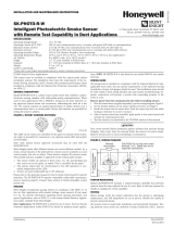
Each detector includes one (1) LED to indicate the device status.
e LED ashes momentarily in normal conditions and ashes
at a fast rate when activated. e LED can be turned o using the
programming soware.
e PAD300-PCD has a maximum spacing limitation of 30. Place
the detector as close to the center of the ceiling as possible. It may be
wall mounted within 12 inches from the ceiling. To minimize false
alarms, avoid placing in areas where excessive dust, humidity, air
movement, or extreme temperature is present. Refer to NFPA 72 for
more details regarding spacing, placement and special applications.
e PAD300-CD and PAD300-PCD communicate on a proprietary
protocol to the addressable re alarm control panel. Each detector
must be connected to either the IPA series, AFC series, or ARC re
alarm control panel for proper operation. For detector sensitivity
settings and supervision, please refer to the panel installation
instructions.
Refer to the company website for the latest revision of this manual.
A. Introduction
1609 Park 370 Pl, Hazelwood, MO 63042
www.pottersignal.com
PAD300-CD
Operating Voltage 24 VDC
Standby Current (*) 300 A
Alarm Indicator Current 1.4 mA
CO Alarm Rating 70 ppm, 150 ppm, 400 ppm
Installation Temp Range 32F to 100F
Operating Humidity Range 0% - 93% (Non-condensing)
Dimension Φ 3.93 in
Weight 2.68 oz
Height 1.22 in
*Standby current is the current the device consumes when the device
is in a non-activated condition and where no communication current
is transmitted to the re alarm control panel.
B. Specications
PAD300-PCD
Operating Voltage 24 VDC
Standby Current (*) 300 A
Alarm Indicator Current 1.4 mA
CO Alarm Rating 70 ppm, 150 ppm, 400 ppm
Smoke Sensitivity 1.1 to 3.5%/
Installation Temp Range 32F to 100F
Operating Humidity Range 0% - 93% (Non-condensing)
Dimension Φ 3.93 in
Weight 3.25 oz
Height 1.42 in
Installation must meet the requirements of the Authority Having Ju-
risdiction (AHJ). It is recommended to follow guidelines as described
in NFPA 72.
1. Before connecting a device to the SLC loop, take the following
precautions to prevent potential damage to the SLC or device.
• Use only the PAD300 series bases PAD300-4DB, PAD300-
6DB, PAD300-SB, PAD300-LFSB, PAD300-RB, and
PAD300-IB (supplied separately).
• Conrm the eld wiring to device is correctly installed on
the base. Refer to the base manual.
• Enable the locking feature if needed. Refer to section D for
details of the locking feature.
2. Set the desired address using the DIP switch located on back of
the sensor. See section E for addressing instructions.
3. Plug detector into base and turn clockwise to secure in place.
C. Installation
KEEP DUST COVER ON DETECTOR DURING
CONSTRUCTION. REMOVE DUST COVER TO ALLOW THE
DETECTOR TO DETECT SMOKE AND CO.
DETECTORS ARE NOT TO BE USED WITH DETECTOR GUARDS
UNLESS THE COMBINATION HAS BEEN EVALUATED AND
FOUND SUITABLE FOR THAT PURPOSE.
CAUTION
D. Locking Feature
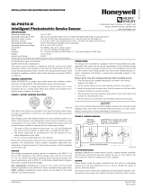
e device includes a tamperproof feature that locks the detec-
tor and does not allow removal without the use of a tool.
Break o tab (gray area in
image). e locking feature
is enabled
Insert a small
screwdriver into slot
to remove detector.

E. Addressing
Detector address can be congured using the
table below for DIP switch position settings.
Testing must meet the requirements of the Authority Having
Jurisdiction (AHJ). It is recommended to follow guidelines as
described in NFPA 72.
It is important to test the product aer installation and periodically to
ensure it functions properly.
CO Aerosol Test
Use Solo C6 CO Aerosol with SDI Solo 330 Dispenser to verify the
CO sensor. Please contact local re and safety equipment distributors
for the specied product. Units failing the aerosol test should be
immediately serviced or replaced.
Smoke Aerosol Test
Use a canned aerosol to spray directly to the side of the detector.
SmokeCheck 25S from HSI Fire and Smoke Centurion from SDi are
acceptable. Please contact local re and safety equipment distributors
to see which products are available. Units failing the aerosol test
should be immediately cleaned. If cleaning cannot restore the unit to
normal, it should be replaced.
Magnet Test
e magnet test provides a quick test to verify the connections and
the detector electronically. is test should not replace the aerosol
test, which is required as part of regular test and maintenance per
NFPA 72.
1. Hold the test magnet in the magnet test area as shown below.
2. e LED ashes rapidly to indicate the detector is in alarm.
3. Remove magnet.
4. Alarm on the re alarm panel should be reset.
5. If the unit fails the magnet test, test the unit with an aerosol
testing spray to conrm any failures.
F. Testing
NOTIFY APPROPRIATE AUTHORITY BEFORE
TESTING THE DETECTOR. PLACE FIRE PANEL IN
WALK TEST
MODE BEFORE CONDUCTING THE FOLLOWING TEST. REFER
TO THE PANEL INSTALLATION MANUAL FOR DETAIL.
CAUTION
magnet location
NOTE: Before cleaning, notify the proper authorities that the system
is undergoing maintenance. Disable the loop or system undergoing
maintenance to prevent unwanted alarms. It is recommended that
the smoke detector be removed from its mounting base for easier
cleaning and that the detector be cleaned at least once a year. Use a
vacuum cleaner to remove dust from the sensing chamber.
POTTER warrants that the equipment herein shall conform to
said descriptions as to all armation of fact and shall be free from
defects of manufacture, labeling, and packaging for a period of ve
(5) years from the invoice date to the original purchaser, provided
that representative samples are returned to POTTER for inspection.
e product warranty period is stated on the exterior of the product
package. Upon a determination by POTTER that a product is not as
warranted, POTTER shall, at its exclusive option, replace or repair
said defective product or parts thereof at its own expense, except
that Purchaser shall pay all shipping, insurance, and similar charges
incurred in connection with the replacement of the defective product
or parts thereof. is Warranty is void in the case of abuse, misuse,
abnormal usage, faulty installation, or repair by unauthorized per-
sons, or if for any other reason POTTER determines that said prod-
uct is not operating properly as a result of causes other than defective
manufacture, labeling, or packaging.
H. Warranty
G. Cleaning
Pry the elastic armelastic arm gently with a small, slotted screwdriver to
remove cage for cleaning.
Manual Number:
54035212X_B
Manual Issue Date:
01/04/2023
Pry the four (4) elastic arms
gently with a small, slotted
screwdriver to remove detector
cover.
POS DIP Switch on POS DIP Switch on POS DIP Switch on
1 1 43 1,2,4,6 85 1,3,5,7
2 2 44 3,4,6 86 2,3,5,7
3 1,2 45 1,3,4,6 87 1,2,3,5,7
4 3 46 2,3,4,6 88 4,5,7
5 1,3 47 1,2,3,4,6 89 1,4,5,7
6 2,3 48 5,6 90 2,4,5,7
7 1,2,3 49 1,5,6 91 1,2,4,5,7
8 4 50 2,5,6 92 3,4,5,7
9 1,4 51 1,2,5,6 93 1,3,4,5,7
10 2,4 52 3,5,6 94 2,3,4,5,7
11 1,2,4 53 1,3,5,6 95 1,2,3,4,5,7
12 3,4 54 2,3,5,6 96 6,7
13 1,3,4 55 1,2,3,5,6 97 1,6,7
14 2,3,4 56 4,5,6 98 2,6,7
15 1,2,3,4 57 1,4,5,6 99 1,2,6,7
16 5 58 2,4,5,6 100 3,6,7
17 1,5 59 1,2,4,5,6 101 1,3,6,7
18 2,5 60 3,4,5,6 102 2,3,6,7
19 1,2,5 61 1,3,4,5,6 103 1,2,3,6,7
20 3,5 62 2,3,4,5,6 104 4,6,7
21 1,3,5 63 1,2,3,4,5,6 105 1,4,6,7
22 2,3,5 64 7 106 2,4,6,7
23 1,2,3,5 65 1,7 107 1,2,4,6,7
24 4,5 66 2,7 108 3,4,6,7
25 1,4,5 67 1,2,7 109 1,3,4,6,7
26 2,4,5 68 3,7 110 2,3,4,6,7
27 1,2,4,5 69 1,3,7 111 1,2,3,4,6,7
28 3,4,5 70 2,3,7 112 5,6,7
29 1,3,4,5 71 1,2,3,7 113 1,5,6,7
30 2,3,4,5 72 4,7 114 2,5,6,7
31 1,2,3,4,5 73 1,4,7 115 1,2,5,6,7
32 6 74 2,4,7 116 3,5,6,7
33 1,6 75 1,2,4,7 117 1,3,5,6,7
34 2,6 76 3,4,7 118 2,3,5,6,7
35 1,2,6 77 1,3,4,7 119 1,2,3,5,6,7
36 3,6 78 2,3,4,7 120 4,5,6,7
37 1,3,6 79 1,2,3,4,7 121 1,4,5,6,7
38 2,3,6 80 5,7 122 2,4,5,6,7
39 1,2,3,6 81 1,5,7 123 1,2,4,5,6,7
40 4,6 82 2,5,7 124 3,4,5,6,7
41 1,4,6 83 1,2,5,7 125 1,3,4,5,6,7
42 2,4,6 84 3,5,7 126 2,3,4,5,6,7
127 1,2,3,4,5,6,7
/