Page is loading ...

Jurisdiction. Proper wire gauges should be used. The installation wires should
be color-coded to limit wiring mistakes and ease system troubleshooting.
Improper connections will prevent a system from responding properly in the
event of a fire.
Remove power from the communication line before installing sensors.
1. Wire the sensor base (supplied separately) per the base wiring diagram.
(See Figure 1.)
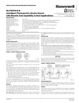
2. Set the desired address on the sensor address switches. (See Figure 2.)
3. Install the sensor into the sensor base. Push the sensor into the base while
turning it clockwise to secure it in place.
4. After all sensors have been installed, apply power to the control panel and
activate the communication line.
5. Test the sensor(s) as described in the TESTING section of this manual.
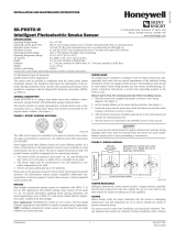
FIGURE 1. WIRING DIAGRAM
2
3
1
2
3
3
1
2
1
(–)
(+)
+-
UL LISTED COMPATIBLE
CONTROL PANEL
CLASS A OPTIONAL WIRING
REMOTE
ANNUNCIATOR
(–)
(+)
C0129-04
CAUTION
Do not loop wire under terminal 1 or 2. Break wire run to provide supervision
of connections.
FIGURE 2. ROTARY ADDRESS SWITCHES
TENS ONES
9
10
11
12
13
14
15
8
7
6
5
4
3
2
1
0
9
8
7
6
5
4
3
2
1
0
C0162-00
UL 268 listed for Open Air Protection
UL 268A listed for Duct Applications
UL 521 listed for Heat Detectors
This sensor must be installed in compliance with the control panel
system installation manual. The installation must meet the require-
ments of the Authority Having Jurisdiction (AHJ). Sensors offer maxi-
mum performance when installed in compliance with the National
Fire Protection Association (NFPA); see NFPA 72. For a complete list
of compatible bases, refer to the Base/Sensor Cross Reference Chart at
systemsensor.com.
GENERAL DESCRIPTION
Model SK-PTIR-W is a plug-in type multi-criteria smoke sensor that offers a
photoelectric sensing chamber combined with a 135°F (57.2°C) fixed tem-
perature heat detector and infrared (IR) sensors. The SK-PTIR-W transmits an
alarm signal due to heat (135°F/57.2°C) per UL 521.
All sensors transmit an analog representation of smoke density over a commu-
nication line to a control panel. Rotary dial switches are provided for setting
the sensor’s address. (See Figure 2.)
Two LEDs on the sensor are controlled by the panel to indicate sensor status.
An output is provided for connection to an optional remote LED annunciator
(P/N RA100Z).
Silent Knight panels offer different features sets across different models. As a
result, certain features of the photoelectric sensors may be available on some
control panels, but not on others.
SK-PTIR-W supports SK protocol mode. The possible features available in the
multi-criteria smoke sensors, if supported by the control unit are:
1. The sensor’s LEDs can operate in three ways—on, off, and blinking–and
they can be set to red, green, or amber. This is controlled by the panel.
2. The remote output may be synchronized to the LED operation or con-
trolled independent of the LEDs.
3. Devices are point addressable up to 159 addresses.
Please refer to the operation manual for the UL listed control panel for specific
operation. The photoelectric sensors require compatible addressable com-
munications to function properly. Connect these sensors to listed-compatible
control panels only.
SPACING
Silent Knight recommends spacing sensors in compliance with NFPA 72. In
low air flow applications with smooth ceilings, space sensors 30 feet apart
(9.1 m). For specific information regarding sensor spacing, placement, and
special applications, refer to NFPA 72 or the System Smoke Detector Applica-
tion Guide, available from Silent Knight.
WIRING GUIDE
All wiring must be installed in compliance with the National Electrical Code,
applicable local codes, and any special requirements of the Authority Having
I56-6618-000
INSTALLATION AND MAINTENANCE INSTRUCTIONS
SPECIFICATIONS
Operating Voltage Range: 15 to 32 VDC
Operating Current @ 24 VDC: 200 uA (one communication every 5 seconds with green LED blink on communication)
Maximum Alarm Current: 2 mA @ 24 VDC (one communication every 5 seconds with red LED solid on)
Maximum Current: 4.5 mA @ 24 VDC (one communication every 5 seconds with amber LED solid on)
Operating Humidity Range: 15% to 90% Relative Humidity, Non-condensing
Operating Temperature Range: 32°F to 100°F (0°C to 38°C)
Air Velocity: 0 to 300 ft./min. (0 to 91.4 m/min.)
Height: 2.0˝ (51 mm) installed in B300-6 Base
Diameter: 6.2˝ (156 mm) installed in B300-6 Base; 4.1˝ (104 mm) installed in B501 Series Base
Weight: 3.4 oz. (95 g)
Isolator Load Rating: 0.0063*
*Please refer to your isolator base/module manual for isolator calculation instructions.
SK-PTIR-W
Multi-Criteria Photoelectric,
Thermal and Infrared Sensor
12 Clintonville Road, Northford, CT 06472-1610
Phone: 203-484-7161 Fax: 203-484-7118
www.silentknight.com
1 I56-6618-000
2/21/2019

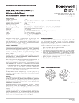
FIGURE 3. FEATURES OF THE PTIR DETECTOR
Base Alignment Notch
Infrared
Light
Pipe
Magnet Test Point
Thermistors
Infrared
Light
Pipe
LEDs
C2050-00
FIGURE 4. CLEANING THE PTIR DETECTOR
Cover
Removal
Tabs
Sensor Cover
Sensing Chamber
Cover and Screen
Infrared
Light
Pipe
Thermistors
Sensing
Chamber
}
C2044-00
CAUTION
Dust covers provide limited protection against airborne dust particles dur-
ing shipping. Dust covers must be removed before the sensors can sense CO.
Remove sensors prior to heavy remodeling or construction.
TAMPER RESISTANCE
Model SK-PTIR-W includes a tamper-resistant capability that prevents removal
from the base without the use of a tool. Refer to the base manual for details on
making use of this capability.
TESTING
Before testing, notify the proper authorities that the system is undergoing
maintenance, and will temporarily be out of service. Disable the system to
prevent unwanted alarms.
All sensors must be tested after installation and periodically thereafter. Test-
ing methods must satisfy the Authority Having Jurisdiction (AHJ). Sensors
offer maximum performance when tested and maintained in compliance with
NFPA 72. Sensitivity readings are available through the fire alarm control
panel (FACP). Refer to the manufac turer’s published instructions for proper
use.
The sensor can be tested in the following ways:
A. Functional: Magnet Test (P/N M02-04-01 or M02-09-00)
This sensor can be functionally tested with a test magnet. The test magnet
electronically simulates smoke in the sensing chamber, testing the sensor
electronics and connections to the control panel.
a. Hold the test magnet in the magnet test area as shown in Figure 3.
b. The sensor should alarm the panel.
Two LEDs on the sensor are controlled by the panel to indicate sensor
status. Coded signals, transmitted from the panel, can cause the LEDs to
blink, latch on, or latch off. Refer to the control panel technical documen-
tation for sensor LED status operation and expected delay to alarm.
NOTE: The magnet test initiates an approximately 10 minute period when
the detector's signal processing software routines are not active.
B. Smoke Entry
Canned aerosol simulated smoke (canned smoke agent) may be used for
smoke entry testing of the smoke detector.
The multi-criteria smoke sensor uses algorithms to process signals re-
ceived from multiple sensors to determine alarm conditions and reduce
false alarms. Therefore, a single burst of canned smoke will not immedi-
ately place the detector into an alarm condition because the detector al-
gorithms correctly determine a burst of canned smoke is not fire. In order
to perform functional testing of the photoelectric sensor, the device must
be placed into test mode. Test mode allows the detector to isolate the indi-
vidual sensors for testing. The device can be placed into test mode through
either of the following methods.
a. Put the device into test mode by holding a test magnet in the magnet
test area as shown in Figure 3 for 6-12 seconds.
NOTE: If the magnet is held in place for too long the fire alarm test func-
tion will be triggered. (See Magnet Test, above.) Reset the panel and pro-
ceed with testing the smoke entry portion of the device.
b. Perform smoke entry testing immediately following the magnet test. The
magnet test initiates an approximately 10 minute period when the detec-
tor’s signal processing software routines are not active.
Once in test mode, test the smoke detector using one of the tested and ap-
proved aerosol smoke products. Refer to the manufacturer’s published instruc-
tions for proper use of the canned smoke agent. When used properly, the
canned smoke agent will cause the smoke detector to go into alarm.
Tested and approved aerosol smoke products include:
Manufacturer Model
HSI Fire and Safety 25S, 30S (PURCHECK)
SDi SMOKE CENTURION , SOLO A10,
SMOKESABRE, TRUTEST, SOLO 365
No Climb TESTIFIRE 2000
CAUTION
Canned aerosol simulated smoke (canned smoke agent) formulas will vary
by manufacturer. Misuse or overuse of these products may have long term
adverse effects on the smoke detector. Consult the canned smoke agent manu-
facturer’s published instructions for any further warnings or caution statements.
C. Direct Heat Method (Hair Dryer of 1000-1500 watts)
A hair dryer of 1000-1500 watts should be used to test the thermistors. Di-
rect the heat toward the thermistor, holding the heat source approximately
12 inches (30 cm) from the detector in order to avoid damaging the plastic
housing. The detector will reset only after it has had sufficient time to
cool. Make sure both thermistors are tested individually.
D. Multi-Criteria Testing
Testifire® by SDi provides testing of the smoke and heat sensors. Consult the
manufacturer’s published instructions for complete usage instructions.
A sensor that fails any of these tests may need to be cleaned as described
under CLEANING, and retested. When testing is complete, restore the system
to normal operation and notify the proper authorities that the system is back
in operation.
CLEANING
Before removing the detector, notify the proper authorities that the smoke
detector system is undergoing maintenance and will be temporarily out of
service. Disable the zone or system undergoing maintenance to prevent un-
wanted alarms.
1. Remove the sensor to be cleaned from the system.
2. Remove the sensor cover by pressing firmly on each of the four removal
tabs that hold the cover in place.
3. Vacuum the screen carefully without removing it. If further cleaning is
required continue with Step 4, otherwise skip to Step 7.
4. Remove the chamber cover/screen assembly by pulling it straight out.
5. Use a vacuum cleaner or compressed air to remove dust and debris from
the sensing chamber.
6. Reinstall the chamber cover/screen assembly by sliding the edge over the
sensing chamber. Turn until it is firmly in place.
7. Replace the cover using the LEDs to align the cover and then gently push-
ing it until it locks into place. Make sure that the thermistors do not be-
come bent under the cover.
8. Reinstall the detector.
9. Test the detector as described in TESTING.
10. Reconnect disabled circuits.
11. Notify the proper authorities that the system is back on line.
SPECIAL NOTE REGARDING SMOKE DETECTOR GUARDS
Smoke detectors are not to be used with detector guards unless the combina-
tion has been evaluated and found suitable for that purpose.
2 I56-6618-000
2/21/2019

SPECIAL APPLICATION
When configured at the fire alarm control panel, this detector is capable of op-
erating in a special application mode such that it has a higher sensitivity than
is normally allowed by UL 268 for areas where early warning is important. In
this mode, the detector does not comply with the Cooking Nuisance Smoke
Test. Detectors (Sampling ports) set to the special application mode are not
suitable for use in areas where cooking appliances may be used. If cooking
appliances are used within the protected space, a normal application detector
or normal application mode must be used for that area.
Special application mode is not for general use and the detector may be more
prone to false alarms if used in unsuitable environments. While no list is
all-inclusive, some examples of unsuitable environments for special applica-
tion mode are areas with airborne particulate or aerosols including sawing,
drilling, and grinding operations, textile or agricultural processing, or areas
with engines that are not vented to the outside. A complete list of aerosol and
particulate sources is available in the Annex of NFPA 72.
Suitable environments for special application mode could include early warn-
ing for hospitals, museums, assisted living and other areas that do not have
airborne particulate or aerosols.
Refer to the fire alarm control panel documentation for information on how to
configure the detector for special application mode.
3 I56-6618-000
2/21/2019

FCC STATEMENT
This device complies with part 15 of the FCC Rules. Operation is subject to the following two conditions: (1) This device may not cause harmful interference,
and (2) this device must accept any interference received, including interference that may cause undesired operation.
NOTE: This equipment has been tested and found to comply with the limits for a Class B digital device, pursuant to Part 15 of the FCC Rules. These limits
are designed to provide reasonable protection against harmful interference in a residential installation. This equipment generates, uses and can radiate radio
frequency energy and, if not installed and used in accordance with the instructions, may cause harmful interference to radio communications. However, there
is no guarantee that interference will not occur in a particular installation. If this equipment does cause harmful interference to radio or television reception,
which can be determined by turning the equipment off and on, the user is encouraged to try to correct the interference by one or more of the following
measures:
– Reorient or relocate the receiving antenna.
– Increase the separation between the equipment and receiver.
– Connect the equipment into an outlet on a circuit different from that to which the receiver is connected.
– Consult the dealer or an experienced radio/TV technician for help.
Please refer to insert for the Limitations of Fire Alarm Systems
DEVICE AND SYSTEM SECURITY
Before installing this product ensure that the
tamper seal on the packaging is present and
unbroken and the product has not been tampered
with since leaving the factory. Do not install this
product if there are any indications of tampering.
If there are any signs of tampering the product
should be returned to the point of purchase.
It is the responsibility of the system owner to
ensure that all system components, i.e. devices,
panels, wiring etc., are adequately protected to
avoid tampering of the system that could result
in information disclosure, spoofing, and integrity
violation.
Silent Knight
®
is a registered trademark of Honeywell International, Inc. Testifire
®
and SOLO
®
are registered trademarks of SDi, LLC.
4 I56-6618-000
©2019 Silent Knight. 2/21/2019
/