Page is loading ...

SCHACHT
STANDARD FLOOR LOOMTM
Assembly InstructIons for DIsAssembleD looms
01.20
Find out more at schachtspindle.com
Schacht Spindle Company 6101 Ben Place Boulder, CO 80301
p. 303.442.3212 f. 303.447.9273
© 2020 Schacht Spindle Company, Inc.
BEFORE YOU BEGIN
■Read through the directions before starting to assemble your
loom.
■You’ll nd a complete labelled diagram of the Wolf loom in your
Maintenance and Warranty manual and at schachtspindle.com.
■The beater is at the front of the loom. The brake is on the right
side of loom.
■All wooden parts of the loom have been nely sanded and nished
with hand-rubbed Danish oil. If at any time you wish to apply more
nish to the loom, use a Danish oil (tung oil and polyurethane
mixture) and hand-rub the wood with a soft lint-free cloth. Be sure to
follow the nish manufacturer’s instructions.
■Unpack the loom parts carefully and compare them to the
drawings on pages 3 and 4. Do not throw away the carton or any of
the packing material until you have checked to see that all of the
parts and hardware bags have been included.
■Follow the exact order of assembly. Take care and work slowly. It
will be easier to assemble your loom with a helper. Some steps may
require two people.
■When you nish assembling the loom, go back over all of the
screws and bolts to make sure they are tight. For screws on parts that
need to pivot, tighten the screw rmly, then unscrew just enough
to allow free movement. It is a good idea to re-tighten all screws on
your loom every few months.
FL3109
FL3111
FL3113
FL3115
FL3121
FL3123
FL3125
FL3127
FL3310
FL3312
FL3314
FL3316
FL3322
FL3324
FL3326
FL3328

TOOLS NEEDED
#2 Phillips screwdriver
Slotted (at) screwdriver
7/16" or adjustable wrench
1/2" and 9/16" wrenches or 2 adjustable wrenches
HARDWARE
Hardware bags may include parts that are not needed for your
loom; there may also be extras included for some parts. Photos
and drawings of hardware are not to scale.
2X fold knobs (plastic knobs with 1" threaded shafts)
2X 1/4" nylon washers
8X 1/4-20 x 2-1/2" Phillips truss head machine screws
8X 1/4-20 barrel nuts
5X 1/2" SAE washers
2X 5/16-18 x 2-1/2" carriage bolts
8X 1/4" USS washers
2X 5/16-18 washer wing nuts
2X 5/16-18 lock nuts
2X 5/16-18 x 1-3/4" hex bolts
12X #12 x 1-1/2" Phillips truss head sheet metal screws
2X 1/4-20 lock nuts
1X 1/2" cap nut
1X 1/2" USS washers
For 8-shaft looms:
2X 3/8" x 5-7/8" jack pivot rods
2X 1/4-20 x 7" carriage bolts
22X 3/8" SAE washers
11X 8/32" hex nuts
11X rubber O-rings
For 4 Now-4 Later looms:
2X 3/8" x 5-7/8" jack pivot rods
2X 1/4-20 x 7" carriage bolts
6X 3/4" plastic spacers
18X 3/8" SAE washers
7X 8/32" hex nuts
7X rubber O-rings
For high castle looms:
12X #8 x 1-1/2" Phillips truss head sheet metal screws
2X 1/4" x 1-1/2" hex bolts
2X 1/4" USS washers
CORDS BAG
36" maple looms:
80X tie-ups
14X 33" apron cords
36" cherry looms:
80X tie-ups
2X 360" apron cords
45" maple looms:
96X tie-ups
18X 33" apron cords
45" cherry looms:
96X tie-ups
2X 480" apron cords
ACCESSORIES PACK
1000X inserted eye heddles
1X brass reed hook
1X 11" boat shuttle & 4" bobbin
1X warp beam crank handle (shown on page 4)
jack pivot rod jack spacer
COMMON HARDWARE
These drawings are not to scale and hardware is not shown in
every size listed.
■Screws and bolts are sized in inches, measured by shaft
length. Measure the shafts of screws and bolts with a metal tape
measure or the ruler on this page. First identify all the screws and
bolts in a hardware bag; then it will be easier to identify any nuts.
■Nuts attach to bolts and machine screws. They have to match
the bolt or machine screw in diameter and thread size. Match the
numbers at the beginning of the description (for instance, 10-24 or
1/4-20) to the corresponding bolt or machine screw.
■Washer sizes refer to the diameter of the hole; measure the
hole with a metal tape measure or the ruler on this page. Different
types of washers, all the same size, are shown here. SAE washers
have the smallest outside diameter, fender washers have the largest
outside diameter, and USS washers are in the middle.
For more help identifying hardware, see our guide at
www.schachtspindle.com/pdfs/schacht-hardware-guide.pdf.
barrel nut washer wing nut cap nut
slim lock nutlock nut hex nut
IDENTIFYING NUTS
IDENTIFYING SCREWS AND BOLTS
carriage bolt Phillips truss head
machine screw
Phillips truss head
sheet metal screw
hex bolt
SAE USS fender
IDENTIFYING WASHERS
0 1 2 3 4 5 6

- 3 -
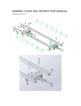
STANDARD FLOOR LOOM PARTS
left loom side: front leg, low/high castle side, upper and lower
rear leg, upper and lower side braces, back beam brace
right loom side: front leg, low/high castle side, upper and lower
rear leg, upper and lower side braces, back beam brace,
ratchet dog, beater pin and holder, brake, brake release
pedal, brake release hold
LEFT LOOM SIDE, HIGH CASTLE (INNER SIDE)
Parts drawings and illustrations for assembly steps show
a 36" low castle loom, unless otherwise indicated.
RIGHT LOOM SIDE, LOW CASTLE (OUTER SIDE)
beater pin
and holder
RIGHT LOOM SIDE, LOW CASTLE (INNER SIDE)
brake
brake
release
pedal
brake
release
hold
ratchet dog
LEFT LOOM SIDE, LOW CASTLE (OUTER SIDE)
front leg
upper
rear leg
lower
rear leg
castle side
upper side
brace
lower side
brace
back
beam
brace

- 4 -
treadle stop
apron bars & lease sticks
warp beam
cloth beam beater top
beater bottom
front castle cross brace
rear castle cross brace upper castle support, low castle loom
front & rear square beams (seen from the top)
treadle assembly, 36" loom
jack assembly
left & right beater
sides (inner sides)
shaft frame with heddle bars & heddle locks, 36" loom
treadle assembly, 45" loom
shaft frame with heddle bars & heddle locks, 45" loom
ratchet advance
lever
warp beam
crank handle
STANDARD FLOOR LOOM PARTS (CONTINUED)
treadle assembly
treadle stop
cloth beam
ratchet advance lever
front castle cross brace
left and right beater sides
beater bottom
beater top
front and rear square beams (parts are identical)
rear castle cross brace
warp beam
jack & lamm assemblies—numbered on stickers
8-shaft looms: 2X #1 jack assemblies, 2X #2 jack assemblies, 2X
#3 jack assemblies, 2X #4 jack assemblies
4 Now-4 Later looms: 2X #1 jack assemblies, 2X #2 jack
assemblies
shaft frames with heddle bars:
8-shaft looms: 8X shaft frames, 16X heddle bars
4 Now-4 Later looms: 4X shaft frames, 8X heddle bars
3X apron bars
2X lease sticks (with holes)
Cherry looms: 2X 1/4" dowels (36" or 45", not shown)
Low castle looms: upper castle support
High castle looms: high castle accessory tray
2X tray long sides
2X tray end pieces
1X tray center piece
2X tray bottoms
HIGH CASTLE ACCESSORY TRAY
end piece center piece
tray
bottoms
tray long sides
(outer & inner
sides)
end piece

- 5 -
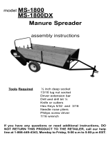
1. Unfold the rear legs.
Parts: left loom side, right loom side
Set a loom side at on the oor. Remove the fold knob and
1/4" nylon washer holding the back beam brace to the
castle side through the middle hole of the brace. Unfold
the upper rear leg so that the hole at the front end of the
back beam brace lines up with the hole in the castle side
(Figure 1). Insert the fold knob through the 1/4" nylon
washer, then screw the knob into the castle side. Repeat
this step for the remaining loom side.
To fold the back beam, insert fold knobs and washers
through the holes in the middle of the back beam braces.
FIGURE 1: UNFOLD THE REAR LEGS
fold knob & 1/4"
nylon washer
upper
rear leg
castle side
(outer side)
back
beam
brace
FIGURE 2: INSTALL THE TREADLE ASSEMBLY
1/4-20 x 2-1/2"
Phillips truss
head machine
screw
right front
leg
treadle support
1/4-20
barrel nut
2. Install the treadle assembly.
Parts: treadle assembly
Hardware: 2X 1/4-20 barrel nuts, 2X 1/4-20 x 2-1/2"
Phillips truss head machine screws
You will need a helper for this step. Stand the loom
sides up with their inner sides facing each other. Set the
treadle assembly between the sides, with the grooves in
the treadles toward the oor. (If you can see the grooves,
the treadle assembly is upside down.)
Fit the ends of the treadle support into the slots in the
bottom of the front legs (Figure 2). Insert a 1/4-20 barrel
nut into one end of the treadle support and hold it in place
with a slotted screwdriver. Insert a 1/4-20 x 2-1/2" Phillips
truss head machine screw through the front leg from its
outer side and screw it into the barrel nut. Repeat on the
other end of the treadle support.
FIGURE 3: ATTACH THE TREADLE STOP
1/4-20 x 2-1/2"
Phillips truss head
machine screw
1/4-20 barrel nut
treadle
stop
right
castle
side
3. Attach the treadle stop.
Parts: treadle stop
Hardware: 2X 1/4-20 barrel nuts, 2X 1/4-20 x 2-1/2"
Phillips truss head machine screws
You will need a helper for this step. Fit the ends of
the treadle stop into the slots in the bottom of the castle
sides (Figure 3). Insert a 1/4-20 barrel nut into one end of
the treadle stop and hold it in place with a at screwdriver.
Insert a 1/4-20 x 2-1/2" Phillips truss head machine screw
through the castle side from its outer side and screw it into
the barrel nut. Repeat on the other end of the treadle stop.

- 6 -
4. Install the cloth beam and ratchet advance lever.
Parts: cloth beam, ratchet advance lever
Hardware: 3X 1/2" SAE washers
On the right axle of the cloth beam, next to the ratchet
gear, place a 1/2" SAE washer, the ratchet advance lever
(oriented as shown in Figure 4A), and a second 1/2" SAE
washer. Insert the cloth beam in the upper side brace of
the right loom side, below the ratchet dog (Figure 4A).
Make sure the ratchet dog is positioned as shown in Figure
4A.
Place a 1/2" SAE washer on the left axle of the cloth beam
and insert the axle into the left loom side (Figure 4B).
You will have to spread apart the loom sides slightly to
complete this step.
Aratchet
gear
ratchet advance lever &
1/2" USS washers
ratchet
dog
upper side brace,
right loom side
FIGURE 4: INSTALL THE CLOTH BEAM
B
hole for left axle
FIGURE 5: ATTACH THE FRONT CASTLE CROSS BRACE
front edge of castle side
(cloth beam not shown)
front castle cross brace:
square holes at the top;
logo right side up
#12 x 1-1/2"
Phillips truss
head sheet
metal screws
5. Attach the front castle cross brace.
Parts: front castle cross brace
Hardware: 4X #12 x 1-1/2" Phillips truss head sheet metal
screws
Orient the front castle cross brace with the logo right
side up and square holes at the top, as shown in Figure 5.
Attach the brace to the front edges of the castle sides, just
below the upper side braces, with two #12 x 1-1/2" Phillips
truss head sheet metal screws at each end.

- 7 -
6. Assemble the beater.
Parts: left and right beater sides, beater bottom, beater top
Hardware: 4X 1/4-20 barrel nuts, 4X 1/4-20 x 2-1/2"
Phillips truss head machine screws, 2X 5/16-18 x 2-1/2"
carriage bolts, 2X 1/4" USS washers, 2X 5/16-18 washer
wing nuts
Attach the beater sides to the beater bottom: Orient the
left and right beater sides with their fronts facing forward,
as shown in Figure 6. Set the beater bottom between the
sides with the groove facing up and the wider side (the
shuttle race) at the front. Insert two 1/4-20 barrel nuts into
the holes at one end of the beater bottom. Insert 1/4-20
x 2-1/2" Phillips truss head machine screws through the
holes of a beater side and tighten them rmly into the
barrel nut. Repeat for the other end of the beater bottom.
Attach the beater top to the sides: If you wish, you can
put the reed in the beater at this point. Place the beater
top with its longer edge in front of the beater sides, so
that the holes in the top line up with the slots in the sides
(Figure 6). From the back of the beater top, insert a 5/16-
18 x 2-1/2" carriage bolt through each hole. Secure each
carriage bolt with a 1/4" USS washer and a 5/16-18 washer
wing nut.
FIGURE 7: INSTALL THE BEATER
B
5/16-18 x 1-3/4" hex bolt 1/4" USS washers 5/16-18 lock nut
beater support lower side brace
7. Install the beater.
Hardware: 2X 5/16-18 x 1-3/4" hex bolts, 6X 1/4" USS
washers, 2X 5/16-18 lock nuts
Orient the beater with its front side facing forward. Set it
in front of the castle sides with the beater sides and beater
supports outside of each lower side brace, as shown in
Figure 7A.
Insert a 5/16-18 x 1-3/4" hex bolt through a 1/4" USS
washer, then through the beater support, then through a
second 1/4" USS washer, then through the outer side of
the lower side brace. From the inner side of the lower side
brace, add another 1/4" USS washer to the hex bolt and
secure with a 5/16-18 lock nut (Figure 7B). Tighten the
lock nut all the way, then loosen one-half to one full turn
to allow the beater to move freely. Repeat this step for the
other beater support.
Abeater support lower side braces
FIGURE 6: ASSEMBLE THE BEATER
5/16-18 x
2-1/2" Phillips
truss head sheet
metal screws
1/4-20
barrel nuts
5/16-18 x
2-1/2" carriage
bolt
1/4" USS
washer
5/16-18
washer
wing nut
front of left
beater side
beater
bottom
beater
top

- 8 -
8. Install the front square beam.
Parts: square beam
Set one of the square beams on the pegs of the front legs,
with its rounded edge facing forward and the squared edge
facing the back of the loom (Figure 8).
FIGURE 8: INSTALL THE FRONT SQUARE BEAM
square beam, rounded edge facing forward
9. Install the jack assemblies.
Use the parts and hardware listed below for your loom. Each jack
assembly has a sticker marked with a number from 1 to 4.
8-shaft looms: 2X 3/8" x 5-7/8" jack pivot rods, 22X 3/8" SAE
washers, 2X #1 jack assemblies, 2X #2 jack assemblies, 2X #3 jack
assemblies, 2X #4 jack assemblies
4 Now-4 Later looms: 2X 3/8" x 5-7/8" jack pivot rods, 18X 3/8"
SAE washers, 6X 3/4" nylon spacers, 2X #1 jack assemblies, 2X
#2 jack assemblies
All looms: Insert the 3/8" x 5-7/8" jack pivot rods into the larger
holes of the front castle cross brace, pointing towards the rear of
the loom. Place two 3/8" SAE washers on each of the jack pivot
rods (Figure 9A).
8-Shaft looms: Place a #1 jack assembly on the rods, followed
by a washer on each rod (Figure 9B). Place the second #1
jack assembly on the rods, followed by a washer on each rod.
Continue in the following order: a #2 jack assembly, a washer
on each rod, another #2 jack assembly, a washer on each rod,
a #3 jack assembly, a washer on each rod, the second #3 jack
assembly, a washer on each rod, a #4 jack assembly, a washer on
each rod, and the second #4 jack assembly. Finish by placing two
more washers on each rod.
4 Now-4 Later looms: Place a #1 jack assembly on the rods,
followed by a washer on each rod (Figure 9B). Place the second
#1 jack assembly on the rods, followed by a washer on each rod.
Continue in the following order: a #2 jack assembly, a washer on
each rod, another #2 jack assembly, a washer on each rod. Place
three 3/4" nylon spacers on each rod. Finish by adding one or
two washers on each of the rods as needed to ll any remaining
space on the jack pivot rods.
FIGURE 9: INSTALL THE JACK ASSEMBLIES
Ajack pivot rod & two 3/8" SAE washers
front castle cross brace (seen from back of loom)
B
#1 jack assembly
3/8" SAE washer

- 9 -
10. Attach the rear castle cross brace.
Parts: rear castle cross brace
Hardware: 4X #12 x 1-1/2" Phillips truss head sheet metal
screws
Place the rear castle cross brace behind the jacks so that
the jack pivot rods t into their holes, which do not go all
the way through the brace (Figure 10). Attach the brace
to the backs of the castle sides, just below the upper side
braces, with two #12 x 1-1/2" Phillips truss head sheet
metal screws at each end.
11. Install carriage bolts on the castle cross braces.
Hardware: 2X 1/4-20 x 7" carriage bolts, 2X 1/4" USS
washers, 2X 1/4-20 lock nuts
Push the jacks down in the center. From the front of the
loom, insert the 1/4-20 x 7" carriage bolts through the
square holes in the front castle cross brace, over the jacks,
and all the way through the holes in the rear castle cross
braces (Figure 11).
From the front of the loom, turn the carriage bolts until
their square parts t into the square holes in the front
castle cross brace. At the rear castle cross brace, place
a 1/4" USS washer on each bolt and secure with a 1/4-
20 lock nut. Tighten the lock nut all the way so that the
carriage bolt fully engages in the hole. Then loosen the
lock nut slightly so that the washer remains loose.
FIGURE 10: ATTACH THE REAR CASTLE CROSS BRACE
#12 x 1-1/2" Phillips truss
head sheet metal screws
holes for jack pivot rods
rear castle cross brace
FIGURE 11: INSTALL CARRIAGE BOLTS
1/4" USS washer1/4-20 lock nut
1/4-20 x 7" carriage bolt

- 10 -
12. Install heddles on the shafts.
Use the parts and hardware listed below for your loom.
8-shaft looms: 8X shaft frames, 16X heddle bars, 1000X
inserted eye heddles
4 Now-4 Later looms: 4X shaft frames, 8X heddle bars,
1000X inserted eye heddles
Lay a shaft frame on a at surface. Push up on the slide
lock on the heddle bar hook and pull the heddle bar out
of the hook (Figure 12A). Release the slide lock. Flex the
heddle bars enough to remove one end from the slot in the
side of the frame. Remove the other end from the frame
(Figure 12B).
Keep the heddles loosely tied until the heddle bars are
installed in the shaft frame. Be sure to keep the heddles
oriented in the same direction for easier threading. Lay the
heddle bars next to the heddles. Carefully slide a group of
heddles onto the heddle bars (Figure 12C).
Replace the heddle bars in the shaft frame. Insert one
end of each heddle bar in the slot in the frame. Flex the
heddle bar and insert the other end into its slot. Divide the
heddles approximately in half and push them to either end
of the heddle bar. Push up on the slide lock and place the
heddle bar back on the hooks (Figure 12D).
Repeat this step for the other shafts. For 4 Now-4 Later
looms, you can install all the heddles on shafts or set them
aside them to install with the 4 Later kit.
FIGURE 12: INSTALL HEDDLES
slide lock
heddle bar
shaft frame
heddle bar hook
A
B
C
D
13. Install the shafts.
Hardware:
8-shaft looms: 11X 8/32" hex nuts, 11X rubber O-rings
4 Now-4 Later looms: 7X 8/32" hex nuts, 7X rubber O-rings
Working from the rear of the loom, slide a shaft frame into
the frontmost channel in the castle sides. Insert the jack
pin into the hole in the center of the bottom of the frame
(Figure 13). Secure the jack pin with an 8/32" hex nut,
then push a rubber O-ring on top of each hex nut.
Install the remaining shaft frames into channels, working
backwards from the front of the loom. The heddle bar
hooks in each shaft frame are slightly off-center. The
hooks should all line up when the shafts are installed in the
loom—if they do not, remove any misaligned shaft frames,
turn them around, and reinstall.
FIGURE 13: INSTALL THE SHAFTS
heddle bar hook
8/32 hex nut with O-ring on top
heddle bar
shaft frame (seen from the back)
jack pin (inside shaft frame)
only 1 shaft & jack
assembly shown

- 11 -
14. Attach the upper castle support (low castle looms
only).
Parts: upper castle support
Hardware: 4X #12 x 1-1/2" Phillips truss head sheet metal
screws
Orient the upper castle support so the logo faces right side
up (Figure 14). Using two #12 x 1-1/2" Phillips truss head
sheet metal screws at each end, attach the support to the
top of the castle sides.
15. Assemble the high castle accessor y tray (high
castle looms only).
Parts: 2X tray long sides, 2X tray end pieces, 1X tray center
piece, 2X tray bottoms
Hardware: 12X #8 x 1-1/2" Phillips truss head sheet metal
screws
Orient one tray long side with the grooved inner side
showing and the groove at the bottom. Place the end pieces
in position with their slots at the bottom, as shown in
Figure 15A. Using six #8 x 1-1/2" Phillips truss head sheet
metal screws, attach the two end pieces and the center
piece to the tray long side.
Slide the tray bottoms into the groove of the long side,
pushing them as close as possible to the center piece—
there will be a small gap between the bottoms and each
end piece (Figure 15B).
Fit the remaining long side, with its grooved inner side
facing inward and the groove at the bottom, on the other
side of the tray bottoms. Attach the long side to the end
pieces and center piece with six #8 x 1-1/2" Phillips truss
head sheet metal screws (Figure 15C).
A
tray long side:
groove at the bottom
end piece: slot at the bottomcenter piece
#8 x 1-1/2" Phillips truss head sheet metal screws
Btray bottom slides
into groove
FIGURE 15: ASSEMBLE THE HIGH CASTLE ACCESSORY TRAY (HIGH CASTLE
LOOMS)
Ctray long side: groove
at the bottom
#8 x 1-1/2" Phillips truss
head sheet metal screws
FIGURE 14: ATTACH THE UPPER CASTLE SUPPORT (LOW CASTLE LOOMS)
#12 x 1-1/2" Phillips truss
head sheet metal screwsupper castle support

- 12 -
16. Install the high castle accessor y tray (high castle
looms only).
Hardware: 2X 1/4" x 1-1/2" hex bolts, 2X 1/4" USS
washers
Insert a 1/4" x 1-1/2" hex bolt through a 1/4" USS washer,
then screw the hex bolt into the threaded hole at the top of
the castle side on its inner side (Figure 16A). Tighten the
hex bolt just enough to hold it in the hole. Repeat with the
remaining hex bolt, washer, and castle side.
Lower the high castle accessory tray into position between
the castle sides and washers, with slots in the end pieces
tting over the hex bolts (Figure 16B). Tighten the hex
bolts securely.
18. Install the warp beam crank handle.
Hardware: 1X warp beam crank handle, 1X 1/2" USS
washer, 1X 1/2" cap nut
On the threaded rod of the warp beam (going through the
upper right rear leg), place a 1/2" USS washer and the
warp beam crank handle, with the wooden handle facing
out. Secure with the 1/2" cap nut (Figure 18).
When you’re weaving, the crank should be pushed off
of the cap nut. To engage the crank for turning the warp
beam, pull the hexagonal hole in the crank onto the cap
nut.
FIGURE 18: INSTALL THE WARP BEAM CRANK HANDLE
17. Install the warp beam.
Parts: warp beam
Hardware: 2X 1/2" SAE washers
Place a 1/2" SAE washer on each end of the warp beam.
Slip the threaded rod (next to the brake hub) through the
hole in the upper right rear leg as far as it will go, moving
the brake cable out of the way. Fit the short rod in the
other end of the warp beam into the hole in the upper left
rear leg—this hole does not go all the way through the leg
(Figure 17). You will have to spread the right and left legs
apart to accomplish this.
FIGURE 17: INSTALL THE WARP BEAM
threaded rod goes
through right leg
short rod ts into hole
in left leg
A
castle side
1/4" USS
washer
1/4" x 1-1/2"
hex bolt
FIGURE 16: INSTALL THE HIGH CASTLE ACCESSORY TRAY (HIGH CASTLE
LOOMS)
B
slot in end piece
right rear leg
1/2" cap nut
warp beam
crank handle
threaded rod
wooden handle
1/2" USS washer

- 13 -
19. Install the brake cable.
Locate the brake bar below the warp beam. Remove the
lock nut, washer, and brake cable from the bolt holding the
brake bar in place. Uncoil the brake cable.
Hold the loose end of the brake cable and wrap it over and
around the brake hub three times. Start next to the loom
leg and wrap towards the loom center, making sure not
to overlap the cable (Figure 19). Press the brake release
pedal and replace the cable, washer, and lock nut on the
bolt. Make sure that the brake bar can pivot freely—if it
does not, slightly loosen the lock nut.
Adjust the friction action by rotating the turnbuckle to
tighten or loosen it. The brake is set properly when you
stand at the rear of the loom and cannot turn the warp
beam away from you with both hands. If the warp beam
turns, tighten the turnbuckle. When you hold the brake
release pedal down, the warp beam should turn freely in
either direction.
FIGURE 20: INSTALL THE BACK SQUARE BEAM
square beam, rounded edge facing back
20. Install the rear square beam.
Parts: square beam
Set one of the square beams on the pegs of the upper rear
legs, with its rounded edge facing back and the squared
edge facing the front of the loom (Figure 20).
FIGURE 19: INSTALL THE BRAKE CABLE
brake bar
washer lock nut
brake release pedal
brake hub & brake cable

- 14 -
21. Install the apron bars.
Parts: 2X apron bars
Cords Bag: apron cords for your loom, listed on page 2
For cherr y looms: see the special instructions for
attaching the apron bars.
For maple looms: Attach the apron cords to the cloth
and warp beams. There is one apron cord for each hole in
the beams. Insert an end of a cord through a hole in the
beam and pull the cord through. Then insert the other end
through the second hole in the end of the cord that you just
put through the beam. Pull rmly on the cord to tighten
(Figure 21A). Repeat across the cloth beam and the warp
beam.
Attach the apron cords to an apron bar: take a pinch of
the cord about 4" from the end (Figure 21B). Insert the
pinched cord through the second hole at the end of the
cord. Pull on the pinched cord until a new loop forms that
is large enough for the apron bar to slip through (Figure
21C). Slide the apron bar through the loop (Figure 21D)
and pull tight. Repeat until all cords are attached to the
apron bar. Attach the other apron bar to its beam in the
same way.
FIGURE 21: INSTALL APRON BARS
FIGURE 22: INSTALL TIE-UPS
22. Install the tie-ups.
Cords Bag: 80X tie-ups for 36" loom, 96X tie-ups for 45"
loom
Loop one end of each tie-up through a hole in the lamm
(Figure 22). For 45" looms, there is one tie-up for every
lamm hole, including the hollow pins at each end of the
lamm. For 36" looms, use only the ten middle holes of each
lamm.
Tie shafts to a treadle by slipping a tie-up cord into the slot
in a treadle (Figure 22). Work from the front lamm to the
rear lamm for each treadle.
After you have completed your tie-up, check each treadle
by pushing it all the way to the oor and releasing it,
making sure that the button of each tie-up cord rests up
against the treadle and that each cord hangs straight down
to the treadle. There is a long groove on the underside of
each treadle end to prevent the tie-ups from slipping off. •
hollow pin at
end of lamm
tie-up cord
end of treadle
(seen from rear)
button
DA B C
loop
/