Page is loading ...

- 1 -
BABY WOLF LOOMTM
Assembly InstructIons for DIsAssembleD looms
FL3001E
FL3003E
FL3011E
FL3013E
FL3021E
FL3023E
Find out more at schachtspindle.com
Schacht Spindle Company 6101 Ben Place Boulder, CO 80301
p. 303.442.3212 f. 303.447.9273
© 2020 Schacht Spindle Company, Inc.
0
1
2
3
4
5
6
BEFORE YOU BEGIN
■Read through the directions before starting to assemble your
loom.
■You’ll nd a complete labelled diagram of the Wolf loom in your
Maintenance and Warranty manual and at schachtspindle.com.
■Wolf loom legs are called out by where they cross each other.
The legs that touch the ground at the front of the loom are called
“inside” legs because they are covered by the “outside” legs when
they cross at the loom center.
■The beater is at the front of the loom. The brake is on the right
side of loom.
■All wooden parts of the loom have been nely sanded and
nished with hand-rubbed Danish oil. If at any time you wish
to apply more nish to the loom, use a Danish oil (tung oil and
polyurethane mixture) and hand-rub the wood with a soft lint-free
cloth. Be sure to follow the nish manufacturer’s instructions.
■Unpack the loom parts carefully and compare them to the
drawings on pages 4 and 5. Do not throw away the carton or any of
the packing material until you have checked to see that all of the
parts and hardware bags have been included.
■Hardware for your loom has been packed into bags for dierent
steps in the assembly process. Open each bag only when you
reach those steps, then identify the pieces included in that bag.
■Follow the exact order of assembly. Take care and work slowly. It
will be easier to assemble your loom with a helper. Some steps may
require two people.
■When you nish assembling the loom, go back over all of the
screws and bolts to make sure they are tight. For screws on parts
that need to pivot, tighten the screw rmly, then unscrew just
enough to allow free movement. It is a good idea to re-tighten all
screws on your loom every few months.
TOOLS REQUIRED
#2 Phillips screwdriver
slotted (at) screwdriver
adjustable wrench or wrenches in the following sizes:
5/16", 7/16", 3/8", 1/2"
COMMON HARDWARE
These drawings are not to scale and hardware is not shown in
every size listed.
■Screws and bolts are sized in inches, measured by shaft
length. Measure the shafts of screws and bolts with a metal tape
measure or the ruler on this page. First identify all the screws and
bolts in a bag; then it will be easier to identify any nuts.
■Nuts attach to bolts and machine screws. They have to match
the bolt or machine screw in diameter and thread size. Match
the numbers at the beginning of the description (for instance, 10-
24 or 1/4-20) to the corresponding bolt or machine screw.
■Washer sizes refer to the diameter of the hole; measure the
hole with a metal tape measure or the ruler on this page. Different
types of washers, all the same size, are shown at right. SAE
washers have the smallest outside diameter, fender washers have
the largest outside diameter, and USS washers are in the middle.
For more help identifying hardware, see our guide at
www.schachtspindle.com/pdfs/schacht-hardware-guide.
pdf.
barrel nut washer wing nut cap nut
hex nutslim lock nutlock nut
IDENTIFYING NUTS
SAE washer USS washer fender washer
IDENTIFYING WASHERS
IDENTIFYING SCREWS AND BOLTS
carriage bolt Phillips truss head
machine screw
Phillips pan head
sheet metal screw
Phillips truss head
sheet metal screw
01.21

- 2 -
Hardware bags may include parts that are not needed for your loom;
there may also be extras included for some parts. Photos are not to scale.
HARDWARE BAG A—STEPS 1–3
4X fold bars
4X 10-24 x 1-1/4" carriage bolts
8X #8 SAE washers
4X 10-24 lock nuts
2X 1/4" USS washers
2X 5/16-18 lock nuts
2X plastic T-nut slides
2X fold knobs (plastic knobs with 1" threaded shafts)
HARDWARE BAG B—STEPS 4–8
6X 1/4-20 x 2" Phillips truss head machine screws
6X 1/4-20 barrel nuts
1X ratchet advance lever
2X 3/8" USS washers
4X #8 x 1-1/2" Phillips truss head sheet metal screws
HARDWARE BAG C—STEPS 9–10
2X #8 x 1-1/2" Phillips truss head sheet metal screws
2X 1/4-20 barrel nuts
2X 1/4-20 x 2" Phillips truss head machine screws
2X 1/4-20 x 2-1/2" carriage bolts
2X 1/4" USS washers
2X 1/4-20 washer wing nuts
2X 5/16-18 slim lock nuts
HARDWARE BAG D—STEPS 11–13
4-shaft looms:
2X 4-shaft jack pivot rods
10X 3/8" SAE washers
4X #8 x 1-1/2" Phillips truss head sheet metal screws
2X 1/4" USS washers
2X 1/4-20 lock nuts
2X 1/4-20 x 4-1/2" carriage bolts
8-shaft and 4 Now-4 Later looms:
2X 8-shaft jack pivot rods
22X 3/8" SAE washers
6X 3/4" nylon jack spacers (only installed on 4 Now-4 Later looms)
4X #8 x 1-1/2" Phillips truss head sheet metal screws
2X 1/4" USS washers
2X 1/4-20 lock nuts
2X 1/4-20 x 7" carriage bolts
HARDWARE BAG E—STEPS 15–17
4-shaft looms:
7X 8/32" hex nuts (includes extras)
7X rubber O-rings (includes extras)
2X #8 x 1-1/2" Phillips truss head sheet metal screws
8-shaft and 4 Now-4 Later looms:
11X 8/32" hex nuts (includes extras)
11X rubber O-rings (includes extras)
2X #8 x 1-1/2" Phillips truss head sheet metal screws
2X #8 x 1-1/4" Phillips pan head sheet metal screws
HARDWARE BAG F—STEPS 18–22
2X 3/8" USS washers
1X brake barrel nut
1X 1/4-20 x 1" Phillips pan head machine screw
1X brake bar and cable
2X 1/4" USS washers
1X 5/16-18 slim lock nut
1X brake S-hook
1X plastic arrow peg
1X brake eye bolt
1X #12 SAE washer
1X brake spring with insert
fold bar
ratchet advance lever
jack pivot rod
jack spacer rubber O-ring
brake barrel nut brake bar and cable
plastic
T-nut slide fold knob
brake S-hook plastic arrow peg
brake eye bolt
brake spring with insert

- 3 -
HARDWARE BAG G—STEPS 23–25
1X warp beam crank handle
1X 3/8" USS washer
1X 3/8" cap nut
2X 1/4-20 barrel nuts
2X 1/4" fender washer
2X back beam knobs (plastic knobs with 2-1/4" threaded shafts)
1X beater pin and chain
1X beater pin holder
1X #6 x 5/8" Phillips pan head sheet metal screw
CORDS BAG
4-shaft looms:
1X brake cord
24X tie-ups
10X 29" apron cords
8-shaft and 4 Now-4 Later looms:
10X treadle aid tie-ups
1X brake cord
80X tie-ups
10X 29" apron cords
ACCESSORIES PACK
4-shaft looms:
1X brass reed hook
400X inserted eye heddles
8-shaft and 4 Now-4 Later looms:
1X brass reed hook
800X inserted eye heddles
beater pin holder beater pin and chain
brake cord apron cords
warp beam crank handle back beam knob
tie-up cords treadle aid cords

- 4 -
BABY WOLF PARTS
left and right pairs of legs
left and right castle sides
treadle assembly
rear leg brace
cloth beam
front castle cross brace
front beam with front beam extension
left and right beater sides
beater race
beater top
jack assemblies—numbered on yellow stickers
4-shaft looms: 2X #1 jack assemblies, 2X #3 jack
assemblies
8-shaft looms: 2X #1 jack assemblies, 2X #2 jack
assemblies, 2X #3 jack assemblies,
2X #4 jack assemblies
4 Now-4 Later looms: 2X #1 jack assemblies,
2X #2 jack assemblies
rear castle cross brace
shaft frames with heddle bars:
4-shaft looms: 4X shaft frames, 8X heddle bars
8-shaft looms: 8X shaft frames, 16X heddle bars
4 Now-4 Later looms: 4X shaft frames, 8X heddle bars
upper castle support
treadle aid bar (8-shaft and 4 Now-4 Later looms only)
treadle aid dowel (8-shaft and 4 Now-4 Later looms only)
warp beam
removable back beam
3X apron bars
2X lease sticks (with holes)
treadle assembly, 4-shaft looms treadle assembly, 8-shaft and 4 Now-4 Later looms
right pair of legs
(inner side)
left pair of legs
(inner side)
left and right beater sides
(inner sides)
left and right castle sides (inner side),
8-shaft and 4 Now-4 Later looms
left and right castle sides (inner side),
4-shaft looms

- 5 -
upper castle supportfront beam & front extension
rear leg brace (small pins on each end) cloth beam
jack assembly
sticker with
jack number
shaft frame with heddle bars and heddle hooks
removable back beam
treadle aid bar & dowel
8-shaft and 4 Now-4 Later looms only
warp beam
beater top (underside) beater bottom
apron bars lease sticks
front castle cross brace
SERIAL NUMBER
rear castle cross brace

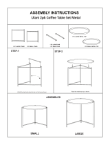
- 6 - FIGURE 2: ATTACH CASTLE SIDES TO LEGS
insert bolt
through hole in
castle sides
left legs & left castle side
(inner side)
right legs & right castle side
(inner side)
2. Attach the castle sides to the legs.
Parts: left and right castle sides
Hardware bag A: 2X 1/4" USS washers, 2X 5/16-18 lock nuts
Place one pair of legs on the oor with its inner side facing up,
so that the bolt shaft connecting the legs points upwards. Orient
the corresponding castle side as shown in Figure 2. Put the bolt
through the hole in the castle side, place a 1/4" USS washer on
the bolt, and secure with a 5/16-18 lock nut. Attach the lock nut
rmly, but not so tightly that the legs cannot fold and unfold.
Repeat this step for the remaining pair of legs and castle side.
ASSEMBLY INSTRUCTIONS
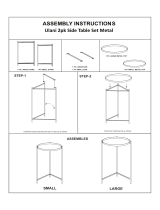
1. Attach the fold bars to the legs.
Parts: left and right pairs of legs
Hardware bag A: 4X fold bars, 4X 10-24 x 1-1/4" carriage bolts,
8X #8 SAE washers, 4X 10-24 lock nuts
NOTE: Wolf loom legs are called out by where they cross
each other. The legs that touch the ground at the front of
the loom are called “inside” legs because they are covered
by the “outside” legs when they cross at the loom center.
Lay the left pair of legs on the oor with the outside leg on top and
pointing to the right, as shown in Figure 1A. Orient the fold bars
as shown in Figure 1A, with round holes meeting between the
legs and the jogs in the bars pointing toward the oor—in other
words, the round holes should be closer to the oor than the
square holes.
On the left inside leg, identify the rst hole above the bolt where
the legs meet. Insert a 10-24" x 1-1/4" carriage bolt through the
square hole of the fold bar, then through a #8 SAE washer, then
through the hole in the inside leg from above, then through
another #8 SAE washer. Secure the carriage bolt with a 10-24 lock
nut (Figure 1B); attach the lock nut just tightly enough to allow
the fold bar to rotate.
On the left outside leg, identify the rst hole above the bolt where
the legs meet. Insert a 10-24 x 1-1/4" carriage bolt through the
square hole of the fold bar, then through a #8 SAE washer, then
through the hole in the outside leg from below, then through
another #8 SAE washer. Secure the carriage bolt with a 10-24 lock
nut (Figure 1B); attach the lock nut just tightly enough to allow
the fold bar to rotate.
Repeat this step for the right pair of legs, orienting them as
shown in Figure 1C. On the right inside leg, attach the fold bar
at the rst hole above the bolt where the legs meet. On the right
outside leg, attach the fold bar at the third hole above the bolt
where the legs meet.
A
carriage bolt &
fold bar attached
from inner side
of leg
10-24 x 1-1/4"
carriage bolt
left outside leg
10-24
lock nut
#8 SAE
washers
left inside leg
B
10-24 x 1-1/4"
carriage bolt
fold bar, end with square hole
#8 SAE washer
10-24
lock nut
#8 SAE washer
leg
FIGURE 1: ATTACH FOLD BARS TO LEGS
C
right inside
leg
right outside
leg

- 7 -
rear leg brace
FIGURE 5: INSTALL THE REAR LEG BRACE barrel nut
1/4-20 x
2" Phillips
truss head
machine
screw
5. Install the rear leg brace.
Parts: rear leg brace
Hardware Bag B: 2X 1/4-20 x 2" Phillips truss head machine
screws, 2X 1/4-20 barrel nuts
Insert a 1/4-20 barrel nut into the hole at one end of the rear leg
brace; hold it in place with masking tape or a slotted screwdriver.
Insert a 1/4-20 x 2" Phillips truss head machine screw into an
outside leg from the outside (Figure 5). Tighten the screw rmly
into the barrel nut.
Repeat this step for the other end of the rear leg brace.
3. Attach the fold bars to the castle.
Hardware bag A: 2X plastic T-nut slides, 2X fold knobs
Turn over the leg and castle side assemblies so the slot in the
castle side faces up. Slide the metal T-nut at the bottom of the slot
to the middle of the slot.
Set the plastic T-nut slide with its wide end up into the slot in the
castle side. Align the holes in the plastic T-nut slide and the metal
T-nut (Figure 3A). Place the ends of the fold bars over the T-nut
slide—rst the outside leg fold bar, then the inside leg fold bar
(Figure 3B). Insert a fold knob through the fold bars and T-nut
slide, then screw the knob into the metal T-nut. Slide the knob to
the bottom of the slot, opening the legs as far as they will go, and
tighten the knob.
Repeat this step for the other castle side.
Note: The fold bars must be stacked as shown in Figure 3B,
with the outside leg fold bar below the inside leg fold bar.
FIGURE 3: ATTACH THE FOLD BARS TO THE CASTLE SIDES
metal T-nut
FRONT OF
LOOM plastic T-nut slide
RIGHT CASTLE SIDE
A
B
outside leg
fold bar
inside leg
fold bar
fold knob
plastic T-nut slide
metal T-nut
4. Attach the treadle assembly to the legs.
Parts: treadle assembly
Hardware Bag B: 2X 1/4-20 x 2" Phillips truss head machine
screws, 2X 1/4-20 barrel nuts
Set the treadle assembly on the oor with the brake release pedal
at the right, as shown in Figure 4A. If you can see the 1/2" round
depressions on the underside of the treadles, the assembly is
upside down and must be turned over. Stand the right leg and
castle side assembly upright, leaning it against a wall or having a
helper hold it in position. Be careful—until the treadle assembly
has been attached at both ends, the leg and castle side assemblies
can fall over easily.
Remove all packing material from the ends of the treadle bar,
leaving any washers or nylon spacers in place. Line up the treadle
assembly with the holes in the leg that do not go all the way
through the legs. The treadle bar ts into the large hole and the
pin at the end of the treadle support ts into the small hole. Insert
the pin and treadle bar into their holes (Figure 4B).
From underneath the treadle support, place a barrel nut into
its hole; hold it in place with masking tape and/or a slotted
screwdriver. Insert a 1/4-20 x 2" Phillips truss head machine
screw into the right inside leg from the outside, then tighten it
rmly into the barrel nut (Figure 4C).
Repeat this step for the left leg and castle side assembly.
FIGURE 4: ATTACH THE TREADLE ASSEMBLY
brake release pedal
treadle assembly
right leg & castle
side assembly
A
B
treadle bar
treadle support
C
barrel nut
1/4-20 x 2" Phillips truss
head machine screw

- 8 -
FIGURE 7: INSTALL FRONT CASTLE CROSS BRACE
front edges of
castle sides
#8 x 1-1/2" Phillips
truss head sheet
metal screws
front castle
cross brace
cloth beam supports
(cut away; cloth beam
not shown)
7. Attach the front castle cross brace.
Parts: front castle cross brace
Hardware Bag B: 4X #8 x 1-1/2" Phillips truss head sheet metal
screws
Orient the front castle cross brace with square holes at the top,
with the logo right side up and visible from the front of the loom
(Figure 7). Attach the front castle cross brace to the front edge of
the castle sides, just below the cloth beam supports, using two #8
x 1-1/2" Phillips truss head sheet metal screws at each end of the
brace.
8. Attach the front beam.
Parts: front beam with attached front beam extension
Hardware Bag B: 2X 1/4-20 x 2" Phillips truss head machine
screws, 2X 1/4-20 barrel nuts
Orient the front beam with the extension facing the front of the
loom, with the rounded long edge of the front beam facing up;
position the front beam between the outside legs (Figure 8).
Insert a 1/4-20 barrel nut in the hole at one end of the front beam;
use masking tape and/or a slotted screwdriver to hold it in place.
Insert a 1/4-20 x 2" Phillips truss head machine screw through
the leg from the outside and tighten it rmly into the barrel nut.
Repeat for the other end of the front beam.
FIGURE 8: INSTALL FRONT BEAM WITH EXTENSION
1/4-20 x 2" Phillips truss
head machine screw
barrel nut
front beam extension
6. Install the cloth beam and ratchet advance lever.
Parts: cloth beam
Hardware Bag B: 1X ratchet advance lever, 2X 3/8" USS washers
Place the ratchet advance lever on the right axle of the cloth
beam, next to the ratchet gear, orienting the lever as shown in
Figure 6A. Place a 3/8" USS washer on each end of the cloth
beam. Insert the cloth beam in the holes in the cloth beam
supports (Figure 6B). You will have to spread apart the cloth
beam supports to complete this step.
FIGURE 6: INSTALL THE CLOTH BEAM AND RATCHET ADVANCE LEVER
B
cloth beam
support
cloth beam
cloth beam support
ratchet advance
lever
A
ratchet
advance
lever
ratchet gear
3/8" USS washer
right cloth
beam support

- 9 -
9. Assemble the beater.
Parts: left and right beater sides, beater bottom, beater top
Hardware Bag C: 2X #8 x 1-1/2" Phillips truss head sheet metal
screws, 2X 1/4-20 barrel nuts, 2X 1/4-20 x 2" Phillips truss head
machine screws, 2X 1/4-20 x 2-1/2" carriage bolts, 2X 1/4" USS
washers, 2X 1/4-20 washer wing nuts
Attach the beater sides to the beater bottom: Orient the left and
right beater sides with their fronts facing forward, as shown
in Figure 9A. Set the beater bottom between the sides with its
grooved wide side (the shuttle race) at the front. Insert a 1/4-20
barrel nut into the hole at one end of the beater bottom. Insert
a 1/4" x 2" Phillips truss head machine screw through the back
hole of a beater side and tighten it rmly into the barrel nut.
Repeat for the other end of the beater bottom. Then screw the
#8 x 1-1/2" Phillips truss head sheet metal screws into the front
holes at each end of the beater bottom.
Attach the beater top to the sides (Figure 9B): If you wish, you
can put the reed in the beater at this point. Place the beater top
with its longer edge in front of the beater sides, so that the holes
in the top line up with the slots in the sides. From the back of the
beater top, insert a 1/4" x 2-1/2" carriage bolt through each hole.
Secure each carriage bolt from the front of the beater with a 1/4"
USS washer and a 1/4-20 washer wing nut.
10. Install the beater assembly.
Hardware Bag C: 2X 5/16-18 slim lock nuts
Orient the beater with its front side facing forward. Place the
metal beater supports onto the bolts pre-installed on the inside
legs (Figure 10A). Secure the beater with a 5/16-18 slim lock nut
on each bolt (Figure 10B). Tighten the lock nuts all the way, then
loosen one-half to one full turn to allow the beater to move freely.
FIGURE 10: INSTALL THE BEATER ASSEMBLY
pre-
installed
bolt
A
5/16-18
slim lock
nut
metal
beater
support
B
FIGURE 9: ASSEMBLE THE BEATER
B
1/4-20
washer
wing nut
1/4" USS washer
beater top
slot for
carriage
bolt
1/4" x 2-1/2"
carriage bolt
A1/4-20 barrel nut
beater bottom
front of left beater side
1/4-20 x 2"
Phillips truss head
machine screw
#8 x 1-1/2"
Phillips truss head
sheet metal screw

- 10 -
11. Install the jacks and lamms.
Parts: jack assemblies listed below for your loom
Hardware Bag D: hardware listed below for your loom
4-shaft looms: 2X 3-1/2" jack pivot rods, 10X 3/8" SAE washers,
2X #1 jack assemblies, 2X #3 jack assemblies
8-shaft looms: 2X 5-5/8" jack pivot rods, 22X 3/8" SAE washers, 2X
#1 jack assemblies, 2X #2 jack assemblies, 2X #3 jack assemblies,
2X #4 jack assemblies
4 Now-4 Later looms: 2X 5-5/8" jack pivot rods, 14X 3/8" SAE
washers, 6X 3/4" nylon spacers, 2X #1 jack assemblies, 2X #2 jack
assemblies
4-shaft Looms: From the rear of the loom, insert the jack pivot
rods into the larger holes of the front castle cross brace. Place one
3/8" SAE washer on each of the rods (Figure 11A). Place a #1 jack
assembly on the jack pivot rods, followed by a 3/8" SAE washer
on each rod (Figure 11B). Place the second #1 jack assembly
on the jack pivot rods, followed by 3/8" SAE washer on each
rod. Place a #3 jack assembly on the jack pivot rods, followed by
another 3/8" SAE washer on each rod. Place the second #3 jack
assembly on the jack pivot rods, and nish with two more 3/8"
SAE washers on each rod (Figure 11C).
8-shaft looms: From the rear of the loom, insert the jack pivot
rods into the larger holes of the front castle cross brace. Place
two 3/8" SAE washers on each of the rods (Figure 11A). Place
a #1 jack assembly on the jack pivot rods, followed by a 3/8"
SAE washer on each rod (Figure 11B). Place the second #1 jack
assembly on the jack pivot rods, followed by 3/8" SAE washer on
each rod. Place a #2 jack assembly on the jack pivot rods, followed
by another 3/8" SAE washer on each rod. Place the second #2
jack assembly on the jack pivot rods, followed by another 3/8"
SAE washer on each rod. Continue with a #3 jack assembly, a 3/8"
SAE washer on each rod, the second #3 jack assembly, a 3/8" SAE
washer on each rod, a #4 jack assembly, a 3/8" SAE washer on
each rod, and the second #4 jack assembly. Finish by placing two
more 3/8" SAE washers on each rod (Figure 11C).
4 Now-4 Later looms: From the rear of the loom, insert the
jack pivot rods into the larger holes of the front castle cross brace.
Place two 3/8" SAE washers on each of the rods (Figure 11A).
Place a #1 jack assembly on the jack pivot rods, followed by a 3/8"
SAE washer on each rod (Figure 11B). Place the second #1 jack
assembly on the jack pivot rods, followed by 3/8" SAE washer
on each rod. Place a #2 jack assembly on the pivot rods, followed
by another 3/8" SAE washer on each rod. Place the second #2
jack assembly on the jack pivot rods, followed by another 3/8"
SAE washer on each rod. Finish by placing two more 3/8" SAE
washers on each rod (Figure 11C), followed by three nylon jack
spacers on each rod.
12. Install the rear castle cross brace.
Parts: rear castle cross brace
Hardware Bag D: 4X #8 x 1-1/2" Phillips truss head sheet metal
screws
Place the rear castle cross brace behind the jacks so that the jack
pivot rods t into their holes—these holes do not go all the way
through the brace (Figure 12). Using two #8 x 1-1/2" Phillips
truss head sheet metal screws at each end, attach the rear castle
cross brace to the castle.
FIGURE 12: INSTALL THE REAR CASTLE CROSS BRACE
rear castle
cross brace
#8 x 1-1/2" Phillips truss
head sheet metal screws
holes for jack pivot rods
FIGURE 11: INSTALL THE JACK ASSEMBLIES
A
back side of
front castle
cross brace
jack pivot rods,
with washer(s) on
each rod
C
two washers on
each rod
all jack
assemblies
B
#1 jack assembly
one washer
on each rod

- 11 -
13. Install carriage bolts on the castle cross braces.
Hardware Bag D: 2X 1/4" USS washers, 2X 1/4-20 lock nuts,
2X 1/4-20 x 4-1/2" carriage bolts for 4-shaft looms or 2X 1/4-20 x
7" carriage bolts for 8-shaft and 4 Now-4 Later looms
Push the jacks down in the center. From the front of the loom,
insert the carriage bolts through the square holes in the front
castle cross brace, all the way through the holes in the rear castle
cross braces (Figure 13).
From the front of the loom, turn the carriage bolts until their
square parts t into the square holes in the front castle cross
brace. At the rear castle cross brace, place a 1/4" USS washer
on each bolt and secure with a 1/4-20 lock nut. Tighten the lock
nut all the way so that the carriage bolt fully engages in the hole.
Then loosen the lock nut slightly so that the washer remains
loose. FIGURE 13: INSTALL CARRIAGE BOLTS ON CASTLE CROSS BRACE
rear castle
cross brace
carriage bolts secured with 1/4" USS washer
and 1/4-20 lock nut
front castle
cross brace
14. Install heddles on the shafts.
Parts:
4-shaft looms: 4X shaft frames, 8X heddle bars, 400X inserted eye
heddles
8-shaft looms: 8X shaft frames, 16X heddle bars, 800X inserted eye
heddles
4 Now-4 Later looms: 4X shaft frames, 8X heddle bars, 800X
inserted eye heddles
Lay a shaft frame on a at surface. Push up on the slide lock
on the heddle bar hook and pull the heddle bar out of the hook
(Figure 14A). Release the slide lock. Flex the heddle bars enough
to remove one end from the slot in the side of the frame. Remove
the other end from the frame (Figure 14B).
Keep the heddles loosely tied until the heddle bars are installed in
the shaft frame. Be sure to keep the heddles oriented in the same
direction for easier threading. Lay the heddle bars next to the
heddles. Carefully slide a group of heddles onto the heddle bars
(Figure 14C).
Replace the heddle bars in the shaft frame. Insert one end of each
heddle bar in the slot in the frame. Flex the heddle bar and insert
the other end into its slot. Divide the heddles approximately in
half and push them to either end of the heddle bar. Push up on
the slide lock and place the heddle bar back on the hooks (Figure
14D).
Repeat this step for the other shafts. For 4 Now-4 Later looms,
you can install all the heddles on shafts or set them aside them to
install with the 4 Later kit.
Note: This process is covered in the video Assembling the
Baby Wolf Loom at youtube.com/user/schachtspindle.
FIGURE 14: INSTALL HEDDLES
slide lock
heddle bar
shaft frame
heddle bar hook
A
B
C
D

- 12 -
15. Install the shafts.
Hardware Bag E:
4-shaft looms and 4 Now-4 Later looms: 7X 8/32" hex nuts,
7X rubber O-rings
8-shaft looms: 11X 8/32" hex nuts, 11X rubber O-rings
Working from the rear of the loom, slide a shaft frame into the
frontmost channel in the castle sides. Insert the jack pin into the
hole in the center of the bottom of the frame (Figure 15). Secure
the jack pin with an 8/32" hex nut, then push a rubber O-ring on
top of the hex nut.
Install the remaining shaft frames into channels, working
backwards from the front of the loom. The heddle bar hooks in
each shaft frame are slightly off-center. The hooks should all
line up when the shafts are installed in the loom—if they do not,
remove any misaligned shaft frames, turn them around, and
reinstall.
Note: This process is covered in the video Assembling the
Baby Wolf Loom at youtube.com/user/schachtspindle.
FIGURE 15: INSTALL THE SHAFTS
heddle bar hook
8/32 hex nut with O-ring on top
heddle bar
shaft frame
jack pin (inside shaft frame)
FIGURE 16: INSTALL THE UPPER CASTLE SUPPORT
upper castle support
#8 x 1-1/2" Phillips truss
head sheet metal screw
#8 x 1-1/2" Phillips truss
head sheet metal screw
16. Install the upper castle support.
Parts: upper castle support
Hardware Bag E: 2X #8 x 1-1/2" Phillips truss head sheet metal
screws
Orient the upper castle support with the logo right side up. Attach
it to the rear of the castle with a #8 x 1-1/2" Phillips truss head
sheet metal screw at each end (Figure 16).
17. Install the treadle aid (8-shaft and 4 Now-4 Later looms
only).
Parts: treadle aid bar, treadle aid dowel
Hardware Bag E: 2X #8 x 1-1/4" Phillips pan head sheet metal
screws
Cords Bag: 10X treadle aid tie-ups
Attach the treadle aid bar: from the back of the loom, attach the
treadle aid bar to the rear castle cross brace with a #8 x 1-1/4"
Phillips pan head sheet metal screw at each end (Figure 17).
Install the treadle aid tie-ups: start at one end of the treadle aid
bar and push a treadle aid tie-up up through one of the holes (an
opened paper clip can be most helpful) and then loop it over the
1/4" dowel. Install treadle aid tie-ups across the entire treadle
aid bar. You will attach the treadle aid tie-ups to the ends of the
treadles in the same manner as you will attach the tie-ups that
control the lamms (Step 26). We recommend using a treadle aid
tie-up on all of the treadles.
only 1 shaft & jack assembly
shown for clarity
FIGURE 17: INSTALL THE TREADLE AID
rear castle
cross brace
treadle aid
bar
holes in treadle
aid bar
treadle aid tie-up
1/4" dowel
#8 x 1-1/4" Phillips pan
head sheet metal screw
left castle
side

- 13 -
FIGURE 18: INSTALL THE WARP BEAM
threaded rod goes through
hole in right leg
short rod ts into hole in
left leg
18. Install the warp beam.
Parts: warp beam
Hardware Bag F: 2X 3/8" USS washers
Place a 3/8" USS washer on each end of the warp beam. Slip the
threaded rod through the hole in the inside right leg as far as
it will go. Fit the short rod in the other end into the hole in the
inside left leg—this hole does not go all the way through the leg
(Figure 18). You will have to spread the right and left inside legs
apart to accomplish this.
20. Install the brake bar and brake cable.
Hardware Bag F: 1X brake bar and cable, 2X 1/4" USS washers,
1X 5/16-18 slim lock nut
Remove all packing material from the pre-installed screw on the
inside right leg, just above the roll pin (Figure 20A). Place the
brake bar and a 1/4" USS washer on this screw, orienting the
brake bar and cable as shown in Figure 20B.
Take the loose end of the brake cable and wrap it under and
around the brake hub three times. Start next to the loom leg and
wrap with loops moving towards the loom center, making sure not
to overlap the cable (Figure 20C). Place the loop end of the cable
on the pre-installed screw over the brake bar and place a 1/4"
USS washer over the cable. Secure everything with a 5/16-20 slim
lock nut (Figure 20C). Make sure that the brake bar can pivot
freely—if it does not, slightly loosen the lock nut.
FIGURE 20: INSTALL BRAKE BAR AND BRAKE CABLE
B
brake bar &
1/4" USS washer
on screw
brake
cable
A
pre-installed screw
with packing material
roll pin
C
brake hub &
brake cable
loop end of brake cable,
1/4" USS washer,
5/16-20 slim lock nut
19. Install the brake barrel nut.
Hardware Bag F: 1X brake barrel nut, 1X 1/4-20 x 1" Phillips pan
head machine screw
Place the brake barrel nut in the groove on the inner side of the
right inside leg. From the outer side of the right inside leg, insert
the 1" Phillips pan head machine screw into the brake barrel nut
and fasten securely (Figure 19).
FIGURE 19: INSTALL THE BRAKE BARREL NUT
brake barrel nut
1/4-20 x 1"
Phillips pan head
machine screw
right inside leg
(inner side)

- 14 -
23. Install the warp beam crank handle.
Hardware Bag G: 1X warp beam crank handle, 1X 3/8" USS
washer, 1X 3/8" cap nut
Locate the threaded rod on the right end of the warp beam. Place
the 3/8" USS washer and then the metal crank handle on the rod,
with the wooden handle facing out. Secure with the the 3/8" cap
nut (Figure 23).
When you’re weaving, the crank should be pushed off of the cap
nut. To engage the crank for turning the warp beam, pull the
hexagonal hole in the crank onto the cap nut.
21. Install the brake cord.
Hardware Bag F: 1X brake S-hook, 1X plastic arrow peg
Cords Bag: 1X brake cord
Hang the brake S-hook in the hole on the rear of the brake bar
(Figure 21). Insert the other end of the S-hook through the
loop in the brake cord. Slip the remaining end of the brake cord
through the hole at the end of the brake release pedal. From
underneath the brake release pedal, insert the plastic arrow peg
into the fth or sixth loop from the end of the brake cord.
FIGURE 21: INSTALL BRAKE CORD
brake cord
S-hook
A
plastic arrow peg
brake release pedal
B
22. Install the brake eye bolt and brake spring.
Hardware Bag F: 1X brake eye bolt, 1X #12 SAE washer, 1X brake
spring with insert
Hook the brake spring to the brake bar in the same hole as the
brake cable (Figure 22). Insert the eye bolt through the #12 SAE
washer, then through the hole in the brake barrel nut, and screw
it into the spring insert.
Tighten the eye bolt until, when you stand at the rear of the loom,
you cannot turn the warp beam away from you with both hands.
When you hold the brake release pedal down, the warp beam
should turn freely in either direction.
You can increase or decrease the tension on the friction brake by
tightening or loosening the eye bolt. There should be small gaps
between the coils of the brake spring once the proper tension is
reached.
FIGURE 22: INSTALL BRAKE EYE BOLT AND BRAKE SPRING
brake spring
brake eye bolt
#12 SAE washer
FIGURE 23: INSTALL THE WARP BEAM CRANK HANDLE
3/8" cap nut
wooden
handle
metal
handle
3/8" USS washer
threaded rod

- 15 -
24. Install the removable back beam.
Parts: back beam
Hardware Bag G: 2X 1/4-20 barrel nuts, 2X 1/4" fender washers,
2X back beam knobs
Slide the back beam into the slots cut in the top of the inside legs.
Insert a 1/4-20 barrel nut into the holes on each end of the back
beam.
Place a 1/4" fender washer on a back beam knob and insert the
knob through the inside leg into the back beam. Tighten the knob
into the barrel nut (Figure 24). Repeat for the other end of the
back beam.
25. Install the beater pin.
Hardware Bag G: 1X beater pin and chain, 1X beater pin holder,
1X #6 x 5/8" Phillips pan head sheet metal screw
Insert the #6 x 5/8" Phillips pan head sheet metal screw through
the hole in the end of the beater pin chain and through the hole
in the beater pin holder (Figure 25A). Fasten the screw into the
small pilot hole in the outside right leg (Figure 25B).
The beater pin holds the beater upright during warping. Hold the
beater upright so the slot in its side aligns with the hole above the
beater pin holder. Push the beater pin through this hole and into
the slot in the beater side (Figure 25C).
FIGURE 25: INSTALL THE BEATER PIN HOLDER
slot in right
beater side
hole in outside
right leg
C
A
beater pin
beater pin
chain
beater pin
holder
#6 x 5/8" Phillips pan
head sheet metal screw
Bhole for using
beater pin
hole for beater
pin holder
outside
right leg slot in right
beater side
FIGURE 24: INSTALL THE REMOVABLE BACK BEAM
1/4" fender washer
back beam knob
1/4-20
barrel nut
back beam

- 16 -
UNFOLDING THE LOOM
■Slightly loosen the fold knobs on each side of the loom.
Generally, a single turn will do.
Loosening the knobs all the way or removing them can
cause the loom to collapse, which could result in injury.
■Stand at the side of the loom. Push the front and removable
back beams together slightly. Pull the slide lock bars out toward
the back of the loom.
■Continue holding onto the front and back beams and allow
the loom to unfold all the way. If there is a warp on the loom, you
may need to hold down the brake release pedal with your foot to
loosen the warp as you unfold the loom.
■When the loom has completely opened, push the fold knobs
down to the bottom of the slots in the castle. Tighten the fold
knobs.
FOLDING THE LOOM
■To prevent treadles from dragging on the oor when the loom
is folded, attach every treadle to at least one tie-up cord.
■Pull out the slide lock bars towards the back of the loom.
■Start folding the loom: loosen the fold knobs one full turn and
pull them up in their slots.
■With one hand on the removable back beam and one hand on
the front beam, push the loom together as far as it will go.
■Tighten the fold knobs. Push in the slide lock bars towards the
front of the loom.
FIGURE 26: INSTALL TIE-UPS
lamm
tie-up cord
end of treadle (seen
from rear)
button
26. Install the tie-ups.
Cords Bag:
4-shaft looms: 24X tie-ups
8-shaft and 4 Now-4 Later looms: 80X tie-ups
Loop one end of each tie-up through a hole in the lamm (Figure
26). For 8-shaft and 4 Now-4 Later looms, there is one tie-up for
every lamm hole. For 4-shaft looms, use only the six middle holes
of each lamm.
Tie shafts to a treadle by slipping a tie-up into the slot in a treadle
(Figure 26). Work from the front lamm to the rear lamm for each
treadle. For 8-shaft and 4 Now-4 Later looms, attach treadle aid
tie-ups to the treadles in the same way.
After you have completed your tie-up, check each treadle by
pushing it all the way to the oor and releasing it, making sure
that the button of each tie-up rests up against the treadle and that
each tie-up hangs straight down to the treadle.
There is a 1/2" round depression on the underside of each treadle
end to prevent the tie-ups from slipping off.
Note: This process is covered in the video Assembling the
Baby Wolf Loom at youtube.com/user/schachtspindle.
27. Attach the apron bars.
Parts: 2X apron bars
Cords Bag: 10X 29" apron cords
For cherry Wolf looms, see the special instructions for attaching
apron bars.
Attach the apron cords to the cloth and warp beams: there is one
apron cord for each hole in the beams. Insert one end of a cord
through a hole in the beam and pull the cord through. Then insert
the other end through the second hole in the end of the cord that
you just put through the beam. Pull rmly on the cord to tighten
(Figure 27A). Repeat across the cloth beam and the warp beam.
Attach the apron cords to an apron bar: take a pinch of the cord
about 4" from the end (Figure 27B). Insert the pinched cord
through the second hole at the end of the cord. Pull on the
pinched cord until a new loop forms that is large enough for
the apron bar to slip through (Figure 27C). Slide the apron bar
through the loop (Figure 27D) and pull tight. Repeat until all
cords are attached to the apron bar. Attach the other apron bar to
its beam in the same way. •
Note: This process is covered in the video Assembling the
Baby Wolf Loom at youtube.com/user/schachtspindle.
FIGURE 27: ATTACH APRON BARS
DA B C
slide lock bar
back beam
fold knob
front beam
/