Page is loading ...

Reference Manual R FR 5010 Version1.4
Page 2
Information in this document is subject to change without
notice. No part of this document may be reproduced or
transmitted in any form or by any means, electronic or
mechanical for any purpose, without express written permission
of LYNX Technik AG.
LYNX Technik AG may have patents, patent applications,
trademarks, copyrights or other intellectual property rights
covering the subject matter in this document. Except as
expressly written by LYNX Technik AG, the furnishing of this
document does not give you any license to patents,
trademarks, copyrights or other intellectual property of LYNX
Technik AG or any of its affiliates.
© LYNX Technik AG 2002-2005 all rights reserved

Reference Manual R FR 5010 Version1.4
Page 3
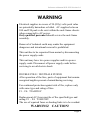
WARNING
Electrical supplies in excess of 50 (fifty) volts peak value
are potentially hazardous or lethal. AC supplies between
100 and 250 peak volts exist within the rack frame chassis
when connected to AC power.
Only qualified personnel should service the rack frame
assembly.
Removal of technical earth may render the equipment
dangerous and intentional removal is prohibited.
This unit has to be separated from mains by disconnecting
the power supply cords.
This unit may have two power supplies and two power
supply cords. Disconnect all power supply cords before
servicing to avoid electric shock.
DOUBLE POLE / NEUTRALE FUSING
After operation of the fuse, parts of equipment that remain
energized might represent a hazard during servicing.
For continued protection against risk of fire, replace only
with same type and rating of fuse.
F1 .. F4: T2AH250V
Replacement AC fuses must be of the specified type and
rating: F1 .. F4: T2AH250V
The use of repaired fuses or shorting links is to be avoided.
WARNING! CAUTION!
Page is loading ...

Reference Manual R FR 5010 Version1.4
Page 5
This Page is intentionally left blank

Reference Manual R FR 5010 Version1.4
Page 6
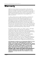
Warranty
LYNX Technik AG warrants that the product will be free from
defects in materials and workmanship for a period of two (2)
years from the date of shipment. If this product proves defective
during the warranty period, LYNX Technik AG at its option will
either repair the defective product without charge for parts and
labor, or will provide a replacement in exchange for the
defective product.
In order to obtain service under this warranty, customer must
notify LYNX Technik of the defect before expiration of the
warranty period and make suitable arrangements for the
performance of service. Customer shall be responsible for
packaging and shipping the defective product to the service
center designated by LYNX Technik, with shipping charges
prepaid. LYNX Technik shall pay for the return of the product to
the customer if the shipment is within the country which the LYNX
Technik service center is located. Customer shall be responsible
for payment of all shipping charges, duties, taxes and any other
charges for products returned to any other locations.
This warranty shall not apply to any defect, failure, or damage
caused by improper use or improper or inadequate
maintenance and care. LYNX Technik shall not be obligated to
furnish service under this warranty a) to repair damage resulting
from attempts by personnel other than LYNX Technik
representatives to install, repair or service the product; b) to
repair damage resulting from improper use or connection to
incompatible equipment; c) to repair any damage or
malfunction caused by the use of non LYNX Technik supplies; or
d) to service a product which has been modified or integrated
with other products when the effect of such modification or
integration increases the time or difficulty servicing the product.
THIS WARRANTY IS GIVEN BY LYNX TECHNIK WITH RESPECT TO THIS
PRODUCT IN LIEU OF ANY OTHER WARRANTIES, EXPRESS OR
IMPLIED. LYNX TECHNIK AND ITS VENDORS DISCLAIM ANY IMPLIED
WARRANTIES OF MERCHANTABILITY OR FITNESS FOR A PARTICULAR
PURPOSE. LYNX TECHNIK`S RESPONISIBILITY TO REPAIR AND
REPLACE DEFECTIVE PRODUCTS IS THE SOLE AND EXCLUSIVE
REMEDY PROVIDED TO THE CUSTOMER FOR BREACH OF THIS
WARRANTY. LYNX TECHNIK AND ITS VENDORS WILL NOT BE LIABLE
FOR ANY INDIRECT, SPECIAL, INCIDENTAL, OR CONSEQUENTAL
DAMAGES IRRESPECTIVE OF WHETHER LYNX TECHNIK OR THE
VENDOR HAS ADVANCE NOTICE OF THE POSSIBILITY OF SUCH
DAMAGES.

Reference Manual R FR 5010 Version1.4
Page 7
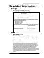
Regulatory information
Europe
Declaration of Conformity
USA
FCC 47 Part 15
This device complies with part 15 of the FCC Rules. Operation is
subject to the following two conditions: (1) This device may not
cause harmful interference, and (2) this device must accept any
interference received, including interference that may cause
undesired operation.
Note: This equipment has been tested and found to comply with the
limits for a Class A digital device, pursuant to the part 15 of the FCC
Rules. These limits are designed to provide reasonable protection
against harmful interference when the equipment is operated in a
commercial environment. This equipment generates, uses, and can
radiate radio frequency energy and, if not installed and used in
accordance with the instruction manual, may cause harmful
interference to radio communications. Operation of this equipment in
a residential area is likely to cause harmful interference in which case
the user will be required to correct the interference at his own
expense
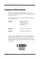
We LYNX Technik AG
Brunnenweg 3
D-64331 Weiterstadt
Germany
Declare under our sole responsibility that the product
TYPE: R FR 5010 / R FR 5011
To which this declaration relates is in conformity with the following
standards (Environments E1-E3):
EN 55103-1 /1996
EN 55103-2 /1996
EN 60950 /2001
following the provisions of 89/336/EEC and 73/23/EEC directives.
Winfried Deckelmann
Weiterstadt, January 2004
Place and date of issue Legal Signature

Reference Manual R FR 5010 Version1.4
Page 8
Contents
Warranty................................................................................... 6
Regulatory information ........................................................... 7
Europe .............................................................................................. 7
Declaration of Conformity........................................................... 7
USA.................................................................................................. 7
FCC 47 Part 15 ............................................................................ 7
Contents................................................................................... 8
Getting Started ...................................................................... 10
Packaging ....................................................................................... 10
Product Description........................................................................ 10
Rack Layout ................................................................................... 12
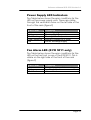
Power Supply ......................................................................... 14
Rear Termination Panel ......................................................... 16
Rack Connections........................................................................... 16
Power Connection ..................................................................... 16
Alarm Connection ..................................................................... 17
Alarm Function.......................................................................... 18
Extend Connection .................................................................... 19
Control Connection ................................................................... 20
LAN Connection ....................................................................... 21
External Sync Connection ......................................................... 21
Alarm/LED Status Indicators ................................................. 22
Power Supply LED Indicators................................................... 23
Fan Alarm LED (R FR 5011 only) ............................................ 23
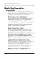
Rack Configuration ............................................................... 24
Assembly........................................................................................ 24
Rack Layout Considerations...................................................... 24
Rear Connection Plates.............................................................. 24
Redundant Power Supply .......................................................... 25
Remote Controller ..................................................................... 25
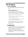
Hot Swapping ........................................................................ 27
Power Supplies............................................................................... 27
Power Supply Failure ................................................................ 27
CardModules ................................................................ 27
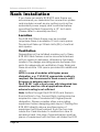
Rack Installation .................................................................... 28
Location..................................................................................... 28
Ventilation................................................................................. 28
Mechanical Installation ............................................................. 29
Front Panel Removal R FR 5010............................................... 29
Front Panel Removal R FR 5011............................................... 29

Reference Manual R FR 5010 Version1.4
Page 9
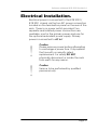
Electrical Installation. ............................................................31
Installation Instructions..........................................................32
Installations-Anweisung ........................................................33
Settings and Control ..............................................................34
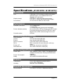
Specifications (R FR 5010 / R FR 5011)..................................35
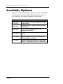
Available Options..................................................................36
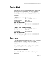
Parts List ..................................................................................37
Service....................................................................................37
Contact Information ..............................................................38

Reference Manual R FR 5010 Version1.4
Page 10
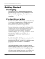
Getting Started
Packaging
The shipping carton and packaging materials
provide protection for the module during transit.
Please retain the shipping cartons in case
subsequent shipping of the product becomes
necessary.
Product Description
The R FR 5010 / R FR 5011 is a high quality 2 RU high
19 inch rack frame enclosure for the LYNX Series
5000 CardModules, designed primarily for
broadcast and professional applications.
The rack frame can accept up to 10 Series 5000
CardModules plus an optional controller card. All
modules are installed from the front. Module
connection plates are supplied with each
CardModule and are mounted on the rear of the
rack to align CardModule installed. All
CardModules and power supplies are hot
swappable.
The R FR 5010 / R FR 5011 features connections for
remote alarming, serial control and a local
extension port. A LAN connection is also provided
for use with the optional R CT 5030 Master
Controller.
Optional redundant power capability can be
installed and two separate AC power connections
are provided for maximum isolation. The power
supplies have sophisticated power filtering with
microprocessor control for power monitoring and
communication with the control system. An on

Reference Manual R FR 5010 Version1.4
Page 11
board multifunction LED has various states to
indicate different alarm conditions and a separate
GPO alarm output is provided for connection to an
external monitoring system.
The system is convection cooled plus forced air-
cooling (low noise fans) so it can be used in areas
where noise level is critical. Power supplies have a
small temperature controlled DC micro fan, which
is only used when needed and is also low-noise
when operating.
The R FR 5011 rack frame has a front cover with
integrated fans for applications, where no external
forced cooling is available or if modules with high
power dissipation are used in this rack frame.
All electrical contacts inside the R FR 5010 / R FR
5011, the CardModules and power supplies are
gold plated ensuring maximum reliability and
protection from corrosion.
The R FR 5010 is the primary building block in the
LYNX Series 5000 CardModule system that provides
high quality, modularity and flexibility in a very small
form factor.

Reference Manual R FR 5010 Version1.4
Page 12
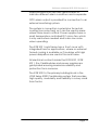
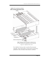
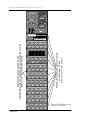
Rack Layout
Figure 2 and 3 shows exploded views of the R FR
5010 / R FR 5011. The Front cover is removed and
not shown.
CardModule
Mid Rack Vertical
Support
Mounting rails on rear of
rack for connection panels
Caution :
Do not obstruct ventialtion
holes on top and bottom sides of rack.
Refer to mounting instructions for more
details.
Figure 2. Exploded rack view

Reference Manual R FR 5010 Version1.4
Page 13
Figure 3 – Exploded rack view
For clarity (to show rack construction) power
supplies, rear termination panel and connection
panels for the modules have been omitted.
Caution :
Do not obstruct ventilation
holes on top and bottom sides of rack.
Refer to mounting instructions for more
details.
Mid Rack Vertical
Support
CardModule
Controller
Rack mounting Screws
Note
. Exploded views are shown for reference only
It is not necessary to disassemble the rack as shown

Reference Manual R FR 5010 Version1.4
Page 14
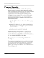
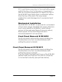
Power Supply
The R FR 5010 / R FR 5011 includes the primary
power supply. A second identical power supply
can be added for redundancy. The Power supply is
a sophisticated design designed for critical
applications and includes power filtering and
integral microprocessor. This monitors the supply
operation and reports into the control system.
Should a fault develop, the errors are alarmed in
the following ways:
• Via the LED located on the front of the supply
(Figure 4).
• Via a GPO alarm via the alarm connector on
the termination panel (figure 5), if a controller
option is fitted
• Via the control system (if installed)
If the redundant power supply is installed, the
system will switch supplies automatically in the
event of primary supply failure, with no interruption
to the normal operation of the rack.
The supply has a noiseless integral DC fan for
cooling.
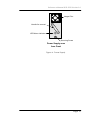
The supply is installed and removed from the front
of the rack. Removing the rack front cover plate
provides access. The supply is secured firmly in
place with a screw located at the bottom front of
the unit (figure 4).

Reference Manual R FR 5010 Version1.4
Page 15
Power Supply seen
from Front
Securing Screw
Integral Fan
Handle for removal
LED Alarm indicator
Figure 4: Power Supply

Reference Manual R FR 5010 Version1.4
Page 16
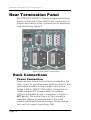
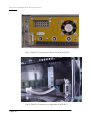
Rear Termination Panel
The R FR 5010/ R FR 5011 has an integral termination
panel on the rear of the rack for the connection of
power and various other connections for expansion
and interfacing. Figure 5
Figure 5 Rear Panel Connections
Rack Connections
Power Connection
There are two power connections provided for the
rack. One is for primary power and the other for the
optional redundant power supply. Input power
range is 100 to 240VAC 50 to 60Hz. Connection is
made using an IEC power cable. For systems
without redundant power connection is made to
AC1 in only. The power fuse is in the connector
assembly (Figure 5) and removal of this small
module will enable fuse exchange. Please ensure
you use the correct fuse rating. (2A).

Reference Manual R FR 5010 Version1.4
Page 17
!
!
A stud is provided on the termination panel for the
connection of an external ground. (Figure 5)
Note: the chassis is permanently grounded via the
AC connections.
Caution
Service to be performed by qualified
personnel only
Caution
Please remove power before attempting to
exchange a power fuse. Only replace the
fuse with a correctly rated replacement. For
safety DO NOT physically disconnect or
isolate the rack from earth for any reason.
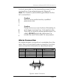
Alarm Connection
An external alarm connection is available from the
rack. This is a 9 pin SubD male connector. Function
and connection information is described below.
Figure 6. Alarm Connector
Pin
Number
Connection
Pin
Number
Connection
1 GND Shield 6 N/C
2 Alarm Major 7 GPI in A
3 Alarm Minor 8 GPI in B
4 Alarm Common 9 GND Shield
5 GND
5
9 6
1

Reference Manual R FR 5010 Version1.4
Page 18
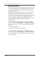
Alarm Function
This function requires the controller option. The user
can assign triggers for the preferred Major / Minor
and No Alarm conditions using the controller and
supplied software.
The alarm connector provides GPO contacts for 2
alarm levels and a GPI input for future use. This
allows for the connection of an external monitoring
system. Alarm conditions are triggered by the
optional control system and will vary depending on
the configuration of the system and user
preferences.
For critical failures in the rack a contact can be
closed between Alarm Minor and Alarm Common.
Some examples of “critical” type failures are listed
below*:
• Over temperature
• Redundant Power Supply Failure
For major failures in the rack a contact can be
closed between Alarm Major and Alarm Common.
Some examples of “major” failures in the rack are:
• Loss of Power

Reference Manual R FR 5010 Version1.4
Page 19
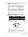
Extend Connection
Bus Extension. This connection is used to interface
racks together when using the optional LYNX
control system. This is a simple (and inexpensive)
way to extend the reach of the host RCT 5020
controller into several more racks fitted with RCT
5010 bus expanders. It uses a proprietary LYNX
control interface and this connection is physically
daisy chained between all connected racks.
Connection details can be seen in the table below.
The connection is a 9 pin SubD female connector.
Function and connection information is described
below.
Connector wiring detail when used for the Bus
Extension
Note the “prop” term refers to proprietary for the
LYNX interface.
Figure 7. Extend Connector
Note. When using this interface all connected racks
must be mounted close together, (preferably with
no space in-between racks), as the distance of this
interface is restricted. Please refer to the R CT 5010
Rack Bus Expander reference manual for more
details on this interface and the cables required.
Pin
Number
Connection
Pin
Number
Connection
1 Prop CLK A 6 Prop CLK B
2 Prop TX A 7 Prop TX B
3 Prop RX B 8 Prop RX A
4 GND 9 Prop SEL 2
5 Prop SEL 1
15
6 9

Reference Manual R FR 5010 Version1.4
Page 20
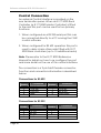
Control Connection
An external Control Interface is provided on the
rear termination panel. When an R CT 5020 Rack
Controller (or R CT 5030 Master Controller) is fitted
to the rack this port can be used for two primary
functions:
1. When configured as a RS 232 serial port this can
be connected directly to a PC running the LYNX
control software.
2. When configured for RS 422 operation this port is
used to daisy chain other racks fitted with R CT
5020 Rack controllers (up to 15 additional racks)
Note. Please refer to the R CT 5020 Reference
Manual for details on how to re-configure the port
and more detail on the use of this control interface.
The connection is a 9 pin SubD female connector.
Function and connection information is described
below.
Connections for RS 422
Connections for RS 232
Pin
Number
Connection
Pin
Number
Connection
1 GND Shield 6 GND
2 TX A 422 7 TX B 422
3 RX B 422 8 RX A 422
4 GND 9 GND Shield
5 GND
Pin
Number
Connection
Pin
Number
Connection
1 GND Shield 6 GND
2 TX 232 7
3 RX 232 8
4 GND 9 GND Shield
5 GND

Reference Manual R FR 5010 Version1.4
Page 21
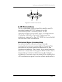
LAN Connection
This is a standard RJ48 connection and is used to
provide standard TCP/IP network control
connectivity into a control system. To be
operational this port requires the R CT 5030 Master
Controller is fitted to the rack. Please see the
reference manual for the R CT 5030 for more details
on the use of this connection
External Sync Connection
An external sync reference (loop through
connection) can be connected for the rack. This
provides a common genlock reference for the
modules installed in the chassis. Sync signal can be
black or composite analog sync NTSC or PAL. This is
to provide a common reference to all modules
installed in the rack and can simplify the distribution
of the reference signal in some system applications.
15
6 9
Fi
g
ure 8. Control Connector

Reference Manual R FR 5010 Version1.4
Page 22
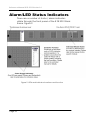
Alarm/LED Status Indicators
There are a number of status / alarm indicators
visible through the front panel of the R FR 5010 Rack
frame. Figure 9.
Figure 9. LEDs and indicator locations and function
Page is loading ...
Page is loading ...
Page is loading ...
Page is loading ...
Page is loading ...
Page is loading ...
Page is loading ...
Page is loading ...
Page is loading ...
Page is loading ...
Page is loading ...
Page is loading ...
Page is loading ...
Page is loading ...
Page is loading ...
Page is loading ...
Page is loading ...
-
 1
1
-
 2
2
-
 3
3
-
 4
4
-
 5
5
-
 6
6
-
 7
7
-
 8
8
-
 9
9
-
 10
10
-
 11
11
-
 12
12
-
 13
13
-
 14
14
-
 15
15
-
 16
16
-
 17
17
-
 18
18
-
 19
19
-
 20
20
-
 21
21
-
 22
22
-
 23
23
-
 24
24
-
 25
25
-
 26
26
-
 27
27
-
 28
28
-
 29
29
-
 30
30
-
 31
31
-
 32
32
-
 33
33
-
 34
34
-
 35
35
-
 36
36
-
 37
37
-
 38
38
-
 39
39


Lynx R FR 5011 User manual
- Type
- User manual
- This manual is also suitable for
Ask a question and I''ll find the answer in the document
Finding information in a document is now easier with AI
Related papers
Other documents
-
Victron energy Lynx Power In Owner's manual
-
Marshall electronic MLYNX15 User manual
-
Intelligent Motion Systems Modular LYNX System User manual
-
 Riverbed SteelConnect SDI-5030 Hardware Installation Manual
-
-
-
Atari LYNX II Quick Manual
-
Marshall Electronics Lynx LCD Universal Monitor User manual
-
 Riverbed SteelConnect SDI-2030 Hardware Installation Manual
-
 PowerRiv HST-PR-5-PRO Operating Instructions Manual


