CIGWELD ProPlus+® Digital Auto-Darkening Welding Helmet User manual
- Category
- Bicycle accessories
- Type
- User manual

Art # A-11920
Operating Manual
Revision: AA Issue Date: March 19, 2013 Manual No.: 0-5276
DIGITAL AUTO-DARKENING
WELDING HELMET
ProPlus+
®

WE APPRECIATE YOUR BUSINESS!
Congratulations on your new Cigweld product. We are proud to
have you as our customer and will strive to provide you with the
best service and reliability in the industry. This product is backed
by our extensive warranty and world-wide service network. To lo-
cate your nearest distributor or accredited service provider call
+1300 654 674, or visit us on the web at www.cigweld.com.au
This Operating Manual has been designed to instruct you on the correct
use and operation of your CIGWELD product. Your satisfaction with this
product and its safe operation is our ultimate concern. Therefore please
take the time to read the entire manual, especially the Safety Precau-
tions. They will help you to avoid potential hazards that may exist when
working with this product.
We have made every effort to provide you with accurate instructions,
drawings, and photographs of the product(s) while writing this manual.
However errors do occur and we apologise if there are any contained
in this manual.
Due to our constant effort to bring you the best products, we may make
an improvement that does not get reflected in the manual. If you are ever
in doubt about what you see or read in this manual with the product you
received, then check for a newer version of the manual on our website
or contact our customer support for assistance.
YOU ARE IN GOOD COMPANY!
The Brand of Choice for Contractors and Fabricators Worldwide.
CIGWELD is the Market Leading Brand of Arc Welding Products for
Victor Technologies International, Inc. We are a mainline supplier to
major welding industry sectors in the Asia Pacific and emerging global
markets including; Manufacturing, Construction, Mining, Automotive,
Engineering, Rural and DIY.
We distinguish ourselves from our competition through market-leading,
dependable products that have stood the test of time. We pride ourselves
on technical innovation, competitive prices, excellent delivery, superior
customer service and technical support, together with excellence in sales
and marketing expertise.
Above all, we are committed to develop technologically advanced prod-
ucts to achieve a safer working environment for industry operators.

!
WARNINGS
Read and understand this entire Manual and your employer’s safety practices before installing,
operating, or servicing the equipment.
While the information contained in this Manual represents the Manufacturer’s best judgement, the
Manufacturer assumes no liability for its use.
Auto-Darkening Welding Helmet
Instruction Manual Number 0-5276 for:
ProPlus Digital Auto Darkening Welding Helmet (Blue) Part Number 454350
ProPlus Digital Auto Darkening Welding Helmet (Web) Part Number 454351
ProPlus Digital Auto Darkening Welding Helmet (Barbed Wire) Part Number 454352
ProPlus Digital Auto Darkening Welding Helmet (Pro Racer) Part Number 454353
Published by:
CIGWELD Pty. Ltd
71 Gower Street
Preston, Victoria, Australia, 3072
www.cigweld.com.au
Copyright 2013 by
CIGWELD
All rights reserved.
A reproduction of this work, in whole or in part, without written permission of the publisher
is prohibited.
The publisher does not assume and hereby disclaims any liability to any party for any loss
or damage caused by any error or omission in this Manual, whether such error results from
negligence, accident, or any other cause.
Publication Date: March 19, 2013
Revision Date:
Record the following information for Warranty purposes:
Where Purchased: ____________________________________
Purchase Date: ____________________________________

Table of Contents
SECTION 1: ARC WELDING SAFETY INSTRUCTIONS AND WARNINGS ................................ 5
1.01 Safety Instructions .................................................................................................... 5
1.02 Declaration of Conformity .........................................................................................7
1.03 Limited Warranty ......................................................................................................7
SECTION 2: INTRODUCTION ............................................................................... 11
2.01 How to Use This Manual .........................................................................................11
2.02 Equipment Identification .........................................................................................11
2.03 Receipt of Equipment ..............................................................................................11
SECTION 3: GENERAL INFORMATION .................................................................... 11
3.01 ProPlus Digital Auto-Darkening Welding Helmet ....................................................11
3.02 User Responsibility .................................................................................................11
SECTION 4: PERSONAL PROTECTION .................................................................... 12
SECTION 5: SPECIFICATIONS .............................................................................. 14
5.01 ProPlus Digital Auto-Darkening Filter Lens .............................................................14
5.02 Contents .................................................................................................................14
SECTION 6: HARNESS ADJUSTMENT .................................................................... 15
SECTION 7: INSTALLATION OF MAGNIFICATION LENS (OPTIONAL) ................................. 16
SECTION 8: CHANGING OF COVER LENSES AND FILTER LENS....................................... 17
SECTION 9: PROPLUS DIGITAL AUTO-DARKENING FILTER LENS CONTROLS ..................... 18
SECTION 10: SPARE PARTS ................................................................................ 22
SECTION 11: BASIC TROUBLESHOOTING ................................................................ 23

ProPlus Auto-Darkening Welding Helmets
Manual 0-5276 5
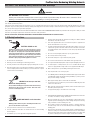
SECTION 1: Arc Welding Safety Instructions and Warnings
!
WARNING
ARC WELDING can be hazardous.
Protect yourself and others from possible serious injury or death. Keep children away. Do not lose these instructions. Read
operating / instruction manual before installing, operating or servicing this product.
Welding products and welding processes can cause serious injury or death, or damage to other equipment or property, if the operator does not strictly observe all safety
rules and take precautionary actions.
Safe practices have developed from past experience in the use of welding and cutting. These practices must be learned through study and training before using this
equipment. Anyone not having extensive training in welding and cutting practices should not attempt to weld. Certain practices apply to equipment connected to power
lines; other practices apply to engine driven equipment.
Safe practices are outlined in the American National Standard Z49.1 entitled: SAFETY IN WELDING AND CUTTING. This publication and other guides to what you should
learn before operating this equipment are listed at the end of these safety precautions.
HAVE ALL INSTALLATION, OPERATION, MAINTENANCE, AND REPAIR WORK PERFORMED ONLY BY QUALIFIED PEOPLE.
1.01 Safety Instructions
ELECTRIC SHOCK can kill.
Touching live electrical parts can cause fatal shocks or severe
burns. The electrode and work circuit is electrically live whenever
the output is on. The input power circuit and machine internal cir-
cuits are also live when power is on. In semiautomatic or automatic
wire welding, the wire, wire reel, drive roll housing, and all metal
parts touching the welding wire are electrically live. Incorrectly
installed or improperly grounded equipment is a hazard.
1. Do not touch live electrical parts.
2. Wear dry, hole-free insulating gloves and body protection.
3. Insulate yourself from work and ground using dry insulating mats or covers.
4. Disconnect input power or stop engine before installing or servicing this equip-
ment. Lock input power disconnect switch open, or remove line fuses so power
cannot be turned on accidentally.
5. Properly install and ground this equipment according to its Owner’s Manual
and national, state, and local codes.
6. Turn off all equipment when not in use. Disconnect power to equipment if it
will be left unattended or out of service.
7. Use fully insulated electrode holders. Never dip holder in water to cool it or lay
it down on the ground or the work surface. Do not touch holders connected to
two welding machines at the same time or touch other people with the holder
or electrode.
8. Do not use worn, damaged, undersized, or poorly spliced cables.
9. Do not wrap cables around your body.
10. Ground the workpiece to a good electrical (earth) ground.
11. Do not touch electrode while in contact with the work (ground) circuit.
12. Use only well-maintained equipment. Repair or replace damaged parts at once.
13. In confined spaces or damp locations, do not use a welder with AC output
unless it is equipped with a voltage reducer. Use equipment with DC output.
14. Wear a safety harness to prevent falling if working above floor level.
15. Keep all panels and covers securely in place.
ARC RAYS can burn eyes and skin;
NOISE can damage hearing.
Arc rays from the welding process produce intense heat and strong
ultraviolet rays that can burn eyes and skin. Noise from some
processes can damage hearing.
1. Use a Welding Helmet or Welding Faceshield fitted with a proper shade of filter
(see ANSI Z49.1 and AS 1674 listed in Safety Standards) to protect your face
and eyes when welding or watching.
2. Wear approved safety glasses. Side shields recommended.
3. Use protective screens or barriers to protect others from flash and glare; warn
others not to watch the arc.
4. Wear protective clothing made from durable, flame-resistant material (wool
and leather) and foot protection.
5. Use approved ear plugs or ear muffs if noise level is high.
FUMES AND GASES can be hazardous
to your health.
Welding produces fumes and gases. Breathing these fumes and
gases can be hazardous to your health.
1. Keep your head out of the fumes. Do not breathe the fumes.
2. If inside, ventilate the area and/or use exhaust at the arc to remove welding
fumes and gases.
3. If ventilation is poor, use an approved air-supplied respirator.
4. Read the Material Safety Data Sheets (MSDS) and the manufacturer’s instruction
for metals, consumables, coatings, and cleaners.
5. Work in a confined space only if it is well ventilated, or while wearing an air-
supplied respirator. Shielding gases used for welding can displace air causing
injury or death. Be sure the breathing air is safe.
6. Do not weld in locations near degreasing, cleaning, or spraying operations.
The heat and rays of the arc can react with vapours to form highly toxic and
irritating gases.
7. Do not weld on coated metals, such as galvanised lead, or cadmium plated steel,
unless the coating is re moved from the weld area, the area is well ventilated,
and if necessary, while wearing an air supplied respirator. The coatings and
any metals containing these elements can give off toxic fumes if welded.

ProPlus Auto-Darkening Welding Helmets
6 Manual 0-5276
WELDING can cause fire or explosion.
Sparks and spatter fly off from the welding arc. The flying sparks
and hot metal, weld spatter, hot work piece, and hot equipment
can cause fires and burns. Accidental contact of electrode or weld-
ing wire to metal objects can cause sparks, over heating, or fire.
1. Protect yourself and others from flying sparks and hot metal.
2. Do not weld where flying sparks can strike flammable material. Remove all
flammables within 35ft (10.7 m) of the welding arc. If this is not possible,
tightly cover them with approved covers.
3. Be alert that welding sparks and hot materials from welding can easily go
through small cracks and openings to adjacent areas.
4. Watch for fire, and keep a fire extinguisher nearby.
5. Be aware that welding on a ceiling, floor, bulkhead, or partition can cause fire
on the hidden side.
6. Do not weld on closed containers such as tanks or drums.
7. Connect work cable to the work as close to the welding area as practical to
prevent welding current from travelling long, possibly unknown paths and
causing electric shock and fire hazards.
8. Do not use welder to thaw frozen pipes.
9. Remove stick electrode from holder or cut off welding wire at contact tip when
not in use.
Flying sparks and hot metal can cause
Injury.
Chipping and grinding cause flying metal. As welds cool, they
can throw off slag.
1. Wear approved face shield or safety goggles. Side shields recommended.
2. Wear proper body protection to protect skin.
CYLINDERS can explode if damaged.
Shielding gas cylinders contain gas under high pressure. If damaged,
a cylinder can explode. Since gas cylinders are normally part of the
welding process, be sure to treat them carefuIIy.
1. Protect compressed gas cylinders from excessive heat, mechanical shocks,
and arcs.
2. Install and secure cylinders in an upright position by chaining them to a station-
ary support or equipment cylinder rack to prevent falling or tipping.
3. Keep cylinders away from any welding or other electrical circuits.
4. Never allow a welding electrode to touch any cylinder.
5. Use only correct shielding gas cylinders, regulators, hoses and fittings designed
for the specific application; maintain them and associated parts in good condi-
tion.
6. Turn face away from valve outlet when opening cylinder valve.
7. Keep protective cap in place over valve except when cylinder is in use or con-
nected for use.
8. Read and follow instructions on compressed gas cylinders, associated equip-
ment, and CGA publication P-1 listed in Safety Standards.

ProPlus Auto-Darkening Welding Helmets
Manual 0-5276 7
1.02 Declaration of Conformity
Manufacturer: CIGWELD
Address: 71 Gower St, Preston
Victoria 3072
Australia
Description of equipment: Safety Equipment. CIGWELD ProPlus Digital Auto-Darkening Welding Helmet.
National Standard and Technical Specifications
The product is designed and manufactured to a number of standards and technical requirements among them are:
a. AS/NZS 1337.1 Section 4 - Eye Protectors for industrial applications.
b. AS/NZS 1338.1 Filters for Eye Protectors.
* Extensive product design verification is conducted at the manufacturing facility as part of the routine design and manufacturing
process, to ensure the product is safe and performs as specified. Rigorous testing is incorporated into the manufacturing process to
ensure the manufactured product meets or exceeds all design specifications.
CIGWELD has been manufacturing and merchandising an extensive equipment range with superior performance, ultra safe operation
and world class quality for more than 30 years and will continue to achieve excellence.
1.03 Limited Warranty
LIMITED WARRANTY: CIGWELD, A Victor Technologies Company, hereafter, “CIGWELD” warrants to customers of its authorised dis-
tributors hereafter “Purchaser” that its products will be free of defects in workmanship or material. Should any failure to conform to this
warranty appear within the time period applicable to the CIGWELD products as stated below, CIGWELD shall, upon notification thereof
and substantiation that the product has been stored, installed, operated, and maintained in accordance with CIGWELD’s specifications,
instructions, recommendations and recognised standard industry practice, and not subject to misuse, repair, neglect, alteration, or ac-
cident, correct such defects by suitable repair or replacement, at CIGWELD’s sole option, of any components or parts of the product
determined by CIGWELD to be defective.
CIGWELD MAKES NO OTHER WARRANTY, EXPRESS OR IMPLIED. THIS WARRANTY IS EXCLUSIVE AND IN LIEU OF ALL OTHERS,
INCLUDING, BUT NOT LIMITED TO ANY WARRANTY OF MERCHANTABILITY OR FITNESS FOR ANY PARTICULAR PURPOSE.
LIMITATION OF LIABILITY: CIGWELD SHALL NOT UNDER ANY CIRCUMSTANCES BE LIABLE FOR SPECIAL, INDIRECT OR CONSEQUEN-
TIAL DAMAGES, SUCH AS, BUT NOT LIMITED TO, LOST PROFITS AND BUSINESS INTERRUPTION. The remedies of the Purchaser
set forth herein are exclusive and the liability of CIGWELD with respect to any contract, or anything done in connection therewith such
as the performance or breach thereof, or from the manufacture, sale, delivery, resale, or use of any goods covered by or furnished by
CIGWELD whether arising out of contract, negligence, strict tort, or under any warranty, or otherwise, shall not, except as expressly
provided herein, exceed the price of the goods upon which such liability is based. No employee, agent, or representative of CIGWELD
is authorised to change this warranty in any way or grant any other warranty.
PURCHASER’S RIGHTS UNDER THIS WARRANTY ARE VOID IF REPLACEMENT PARTS OR ACCESSORIES ARE USED WHICH IN
CIGWELD’S SOLE JUDGEMENT MAY IMPAIR THE SAFETY OR PERFORMANCE OF ANY CIGWELD PRODUCT. PURCHASER’S RIGHTS
UNDER THIS WARRANTY ARE VOID IF THE PRODUCT IS SOLD TO PURCHASER BY NON-AUTHORISED PERSONS.
The warranty is effective for the time stated below beginning on the date that the authorised distributor delivers the products to the
Purchaser. Notwithstanding the foregoing, in no event shall the warranty period extend more than the time stated plus one year from
the date CIGWELD delivered the product to the authorised distributor.

ProPlus Auto-Darkening Welding Helmets
8 Manual 0-5276
Terms of Warranty – July 2007
1. The Trade Practices Act 1974 (Commonwealth) and similar State Territory legislation relating to the supply of goods and services,
protects consumers’ interests by ensuring that consumers are entitled in certain situations to the benefit of various conditions,
warranties, guarantees, rights and remedies (including warranties as to merchantability and fitness for purpose) associated
with the supply of goods and services. A consumer should seek legal advice as to the nature and extent of these protected
interests. In some circumstances, the supplier of goods and services may legally stipulate that the said conditions, warranties,
guarantees, rights and remedies are limited or entirely excluded. The warranties set out in Clause 2 shall be additional to any
non-excludable warranties to which the Customer may be entitled pursuant to any statute.
2. Subject to Clause 3. CIGWELD gives the following warranties to the Customer:
Insofar as they are manufactured or imported by CIGWELD, goods will upon delivery be of merchantable quality and reasonably
fit for the purpose for which they are supplied by CIGWELD.
CIGWELD will repair or, at its option, replace those of the goods which, upon examination, are found by CIGWELD to be defec-
tive in workmanship and/or materials.
CIGWELD reserves the right to request documented evidence of date of purchase.
3. The Warranty in Clause 2;
Is conditional upon:
The Customer notifying CIGWELD or our Accredited Distributor in writing of its claim within seven (7) days of becoming aware
of the basis thereof, and at its own expense returning the goods which are the subject of the claim to CIGWELD or nominated
Accredited Distributor/Accredited Service Provider.
The goods being used in accordance with the Manufacturer’s Operating Manuals, and under competent supervision.
Does not apply to:
Obsolete goods sold at auction, second-hand goods and prototype goods.
Breakdown or malfunction caused by accident, misuse or normal wear and tear.
Repairs or replacement made other than by CIGWELD or Accredited Service Providers, unless by prior arrangement with CIG-
WELD.
Replacement parts or accessories which may affect product safety or performance and which are not manufactured, distributed
or approved by CIGWELD.
4. CIGWELD declares that, to the extent permitted by law, it hereby limits its liability in respect of the supply of goods which are
not of a kind ordinarily acquired for personal, domestic or household use or consumption to any one or more of the following
(the choice of which shall be at the option of CIGWELD).
The replacement of the goods or the supply of equivalent goods.
The repair of goods.
The payment of cost of replacing the goods or acquiring equivalent goods.
The payment of the cost of having goods repaired.
5. Except as provided in Clauses 2 to 4 above, to the extent permitted by statute, CIGWELD hereby excludes all liability for any
loss, damage, death or injury of any kind whatsoever occasioned to the Customer in respect of the supply of goods including
direct, indirect, consequential or incidental loss, damage or injury of any kind.

ProPlus Auto-Darkening Welding Helmets
Manual 0-5276 9
Warranty Schedule
These warranty periods relate to the warranty conditions in clause 2. All warranty periods are from date of sale from the Ac-
credited Distributor of the equipment. Notwithstanding the foregoing, in no event shall the warranty period extend more than the
time stated plus one year from the date CIGWELD delivered the product to the Accredited Distributor. Unless otherwise stated
the warranty period includes parts and labour.
CIGWELD reserves the right to request documented evidence of date of purchase.
CIGWELD SAFETY EQUIPMENT WARRANTY PERIOD
ProPlus Digital Auto-Darkening Welding Helmet ......................................................... ..............2 years
ACCESSORIES
Cover Lenses ............................................................................................................... ............1 month
Sweat Band ................................................................................................................. .............1 month
Welding Helmet Bag .................................................................................................... ............3 months
Please note that the information detailed in this statement supersedes any prior published data produced by CIGWELD.
!
WARNING
For the purpose of safety and performance and to protect your CIGWELD Equipment Warranty always use genuine CIGWELD
replacement parts and accessories.

ProPlus Auto-Darkening Welding Helmets
10 Manual 0-5276
CIGWELD Pty Ltd
ABN: 56 007 226 815
A Victor Technologies Company
71 Gower Street
Preston VIC 3072 Australia
T: +61 3 9474 7400
F: +61 3 9474 7391
enquiries@cigweld.com.au
www.cigweld.com.au
CIGWELD Terms of Warranty - 2013
warranty) supplied with goods or services must comply with the mandatory requirements in
the new Australian Consumer Law and the Trade Practices (Australian Consumer Law)
Amendment Regulations (2010) (No.1).
This Warranty Statement should be read in conjunction with the Warranty Schedule contained
in the operating instructions of the product. This schedule contains the warranty period
applicable to the product
Any claim under this warranty must be made within the warranty period which commences on
the date of purchase of the product. To make a claim under the warranty, take the product
(with proof of purchase from a Cigweld Accredited Seller) to the store where you purchased
the product or contact Cigweld Customer Care 1300 654 674 for advice on your nearest
Service Provider.
All costs associated with lodging the warranty claim including the return of goods to Cigweld
or our Nominated Accredited Distributor / Accredited Service Provider are the responsibility of
the consumer.
This warranty is given.
Cigweld Pty Ltd
A.B.N. 56007226815
71 Gower Street, Preston
Victoria, Australia, 3072
Phone: 1300 654 674
Email: enquiries@cigweld.com.au
Website: www.cigweld.com.au
This warranty is provided in addition to other rights and remedies you have under law:
Our goods come with guarantees which cannot be excluded under the Australian Consumer
Law. You are entitled to replacement or refund for a major failure and to compensation for
other reasonably foreseeable loss or damage. You are also entitled to have the goods
repaired or replaced if the goods fail to be of acceptable quality and the failure does not
amount to a major failure.
Failures due to incorrect use are not covered by this warranty and consumers are reminded to
only use the product in accordance with the Operating Instruction supplied with the product.
Additional copies of Operating Instructions are available from Cigweld Customer Care
1300 654 674 or the Website.

ProPlus Auto-Darkening Welding Helmets
Manual 0-5276 11
SECTION 2: Introduction
2.01 How to Use This Manual
This Owner’s Manual usually applies to just the underlined speci-
fication or part numbers listed. If none are underlined, they are all
covered by this manual.
To ensure safe operation, read the entire manual, including the
chapter on safety instructions and warnings.
Throughout this manual, the word WARNING, CAUTION and NOTE
may appear. Pay particular attention to the in formation provided
under these headings. These special annotations are easily recog-
nised as follows:
!
WARNING
Gives information regarding possible personal injury.
Warnings will be enclosed in a box such as this.
CAUTION
Refers to possible equipment damage. Cautions will
be shown in bold type.
NOTE
Offers helpful information concerning certain operating
procedures. Notes will be shown in italics.
2.02 Equipment Identification
The product identification number is printed on the outer shipping
carton. Record this number for future reference.
2.03 Receipt of Equipment
When you receive the equipment, check it against the invoice to
make sure it is complete and inspect the equipment for possible
damage due to shipping. If there is any damage, notify the carrier
immediately to file a claim. Furnish complete information concerning
damage claims or shipping errors to:
CIGWELD, Customer Care Department, 71 Gower St, Preston,
Victoria, Australia, 3072.
Include all equipment identification numbers as described above
along with a full description of the parts in error.
Additional copies of this manual may be purchased by contacting
CIGWELD, Customer Care Department, at the address given above.
Include the Owner’s Manual number and equipment identification
numbers.
SECTION 3: General Information
3.01 ProPlus Digital Auto-Darkening Welding Helmet
ProPlus Digital Auto-Darkening welding helmets are designed to protect the eye and face from sparks, spatter and harmful radiation
under normal welding conditions. After pressing the “ON/ MODE” button, Auto-Darkening filter is ready to use and automatically changes
from a light state to a dark state when an arc is struck, and it returns to the light state when welding stops. The welding helmet will
automatically off after half an hour not use.
The only thing you need to do before your welding is to press the “ON/ MODE” button, adjust the position of the headband and select
the application mode, the correct shade number, the sensitivity, delay for your application.
To ensure your complete satisfaction with your new ProPlus Digital Auto-Darkening Welding Helmet and to realise a safer work environ-
ment, we ask that you read the following Operating Manual thoroughly before use.
3.02 User Responsibility
This product will perform as per the information contained herein when installed, operated, maintained and repaired in accordance
with the instructions provided. This equipment must be checked periodically. Defective equipment should not be used. Parts that are
broken, missing, plainly worn, distorted or contaminated, should be replaced immediately. Should such repairs or replacements become
necessary, it is recommended that such repairs be carried out by appropriately qualified persons approved by CIGWELD. Advice in this
regard can be obtained by contacting an accredited CIGWELD Distributor.
This product or any of its parts should not be altered from standard specification without prior written approval of CIGWELD. The
user of this product shall have the sole responsibility for any malfunction which results from improper use or unauthorised modifica-
tion from standard specification, faulty maintenance, damage or improper repair by anyone other than appropriately qualified persons
approved by CIGWELD.

ProPlus Auto-Darkening Welding Helmets
12 Manual 0-5276
SECTION 4: Personal Protection
!
WARNING
Prior to welding check operation of the filter lens, if the lens does not darken DO NOT COMMENCE WELDING. If during
welding the filter does not darken IMMEDIATELY STOP WELDING.
The radiation from an electric arc during the welding process can seriously harm eyes and skin. It is essential that the following
precautions be taken:
When electric arc welding, it is a requirement to use a welding helmet or welding handshield that complies to a relevant standard.
Protective filter lenses are provided to reduce the intensity of radiation entering the eye thus filtering out harmful infra-red, ultra-
violet radiation and a percentage of the visible light. Such filter lenses are incorporated into this Welding Helmet. To prevent
damage to the filter lenses from molten or hard particles an additional hard clear glass or special plastic external cover lens is
provided. This cover lens should always be kept in place and replaced before the damage impairs your vision while welding.
!
WARNING
For machine disc cutting, scaling, grinding and machining of metals and the like, additional eyeshields or faceshields with
appropriate impact rating should be used. Refer to AS/NZS1336 for full details of the appropriate protection for industrial
applications.
!
WARNING
The indicated filter lens shade numbers are minimum. If any discomfort is felt, higher shade numbers should be selected.
Recognised standards for recommended practices for occupational eye protection include AS/NZS 1336 and EN 175.
Gloves should be flameproof gauntlet type to protect hands and wrists from heat burns and harmful radiations. They should
be kept dry and in good repair.
Protective clothing must protect the operator from burns, spatter and harmful radiation. Woollen clothing is preferable to cot-
ton because of its greater flame resistance. Clothing should be free from oil or grease. Wear leggings and spats to protect the
lower portion of the legs and to prevent slag and molten metal from falling into boots or shoes.

ProPlus Auto-Darkening Welding Helmets
Manual 0-5276 13
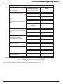
Recommended Protective Filters for Electric Welding
Description of Process
Approximate Range of
Welding Current in Amps
Minimum Shade Number of
Filter(s)
Air - Arc Gouging Less than or equal to 400 12
Flux-cored Arc Welding (FCAW)
-with or without shielding gas
Less than or equal to 300 11
300 to 400 12
400 to 500 13
Greater than 500 14
Gas Metal Arc Welding (GMAW)
(MIG)
-Aluminium and Stainless Steel
- other than Aluminium and Stainless
Steel
Less than or equal to 250 12
250 to 350 13
Less than or equal to 150 10
150 to 250 11
250 to 300 12
300 to 400 13
400 14
Gas Tungsten Arc Welding (GTAW)
(TIG)
Less than or equal to 100 10
100 to 200 11
200 to 250 12
250 to 350 13
Greater than 350 14
Manual Metal Arc Welding
- covered electrodes (MMAW)
Less than or equal to 100 8
100 to 200 10
200 to 300 11
300 to 400 12
Greater than 400 13
Plasma - Arc Cutting
50 to 100 10
100 to 400 12
400 to 800 14
Plasma - Arc Spraying — 15
Plasma - Arc Welding
Less than or equal to 20 8
20 to 100 10
100 to 400 12
400 to 800 14
Resistance Welding
— Safety Spectacles or eye
shield
Submerged - Arc Welding — 2(5) *
* A shade 5 filter is recommended for watching molten pool in electroslag welding.
Table 4-1 Recommended Protective Filters for Electric Welding
Refer to standard AS/NZS 1338.1:2012 for comprehensive information regarding Table 4-1.

ProPlus Auto-Darkening Welding Helmets
14 Manual 0-5276
SECTION 5: Specifications
5.01 ProPlus Digital Auto-Darkening Filter Lens
Description Auto-Darkening Filter Lens
Optical Class: 1/1/1/2
Viewing Area: 97x62mm
Cartridge Size: 133x114x9mm
Number of Sensors: 4 Optical Sensors
Modes: Welding, Cutting, Grinding
Light State: Shade No. 4
Grind State: Shade No. 4
Cutting Mode Shades:
(Oxy/Fuel Welding And Cutting)
Shade No. from 5 to 8
Welding Mode Shades:
(MIG, TIG, Stick Arc Welding)
(Plasma Cutting & Plasma
Welding)
Shade No. from 8 to 13
Shade Control: Internal, Variable Shade, Digitally Controlled
Power On/Off: Manual-On, Auto-Off
Sensitivity Control: Low — High, Digitally Controlled
UV/IR Protection: All shades provide continuous UV/IR protection
Power Supplies: Replaceable 2 x CR2450 Lithium Batteries plus Solar Cell
Switching Time (Light to Dark): 0.00004 (1/25,000) Seconds
Delay Time: 0.1 ~ 1.0s
Low Amperage TIG Rated: ≥ 2 amps DC; ≥ 2 amps AC
Operating Temperature: -10°C ~ +55°C
Storing Temperature: -20°C ~ +70°C
Helmet Material: High Impact Resistant Nylon
Total Weight: 500g
Application range:
MIG (GMAW/FCAW), Stick (MMAW),TIG (GTAW), Plasma Arc Cutting (PAC), Plasma Arc
Welding (PAW), Air Carbon Arc Cutting (CAC-A), Oxyfuel Gas Welding (OFW), Oxygen
Cutting (OC), Grinding; DO NOT USE for Laser Welding
Table 5-1 Specifications
NOTE
Due to variations that can occur in manufactured products, claimed performance, voltages, ratings, all capacities, measure-
ments, dimensions and weights quoted are approximate only. Achievable capacities and ratings in use and operation will
depend upon correct installation, use, applications, maintenance and service.
5.02 Contents
CONTENTS - PROPLUS DIGITAL AUTO-DARKENING WELDING HELMET
Description Quantity
ProPlus Digital Auto-Darkening Welding Helmet 1
Welding Helmet Bag 1
Front Cover Lens 3
Rear Cover Lens 2
Sweat Band 1
Operating Manual 1
Table 5-2 Packing List

ProPlus Auto-Darkening Welding Helmets
Manual 0-5276 15
SECTION 6: Harness Adjustment
!
WARNING
The helmet comes ready assembled, but before it can be used it must be adjusted to fit the user properly and set up for
delay time, sensitivity and shade level.
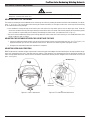
ADJUSTING THE FIT OF THE HELMET
The overall circumference of the headband can be made larger or smaller by rotating the knob on the back of the headband. (See adjust-
ment “Y” in Fig. 6-1). This can be done whilst wearing the helmet and allows just the right tension to be set to keep the helmet firmly
on the head without it being too tight.
• If the headband is sitting too high or too low on your head, adjust the strap which passes over the top of your head. To do this
release the end of the band by pushing the locking stud out of the hole in the band. Slide the two portions of the band to a greater
or lesser width as required and push the locking stud through the nearest hole. (See adjustment “W” in Fig. 6-1).
• Test the t of the headband by lifting up and closing down the helmet a few times while wearing it. If the headband moves while
tilting, re-adjust it until it is stable.
ADJUSTING THE DISTANCE BETWEEN THE HELMET AND THE FACE
1. Loosen the adjustment knob on both sides of the helmet and slide it closer or further from your face. (See T in Fig. 6-1). It is
important that both eyes are the same distance from the lens. Otherwise the darkening effect may appear uneven.
2. Re-tighten the adjustment knob when adjustment is complete.
ADJUSTING VIEW ANGLE POSITION
TILT: Tilt adjustment is located on right side of helmet. Loosen the right side headgear tension knob and push the top end of the adjust-
ment lever outward until the lever’s Stop Tab clears the notches. Then rotate the lever forward or back to the desired tilt position. To
adjust the horizontal adjustment slide the harness forward or backward to desired position. Retighten the tension knob to secure into
place. (see Fig. 6-2)
Top
Art # A-11793
Tilt Adjustment
Horizontal
Adjustment
Art # A-11794
Figure 6-1 Harness Adjustment Figure 6-2 Tilt and Horizontal Adjustment

ProPlus Auto-Darkening Welding Helmets
16 Manual 0-5276
SECTION 7: Installation of Magnification Lens (Optional)
CIGWELD magnification lenses magnify the work area substantially to assist the welder in maintaining the high standard required.
!
WARNING
Before installing the magnification lens, ensure that the rear cover lens is in place.
1. Magnification Lens Frame
Magnification lens frame shown on left without magnification lens installed.
2. Installing Magnification Lens
To install magnification lens, slide the magnification lens from the top of the magnification
lens frame and slide it down until it comes in contact with the last set of tabs on the
magnification lens frame. Ensure that the lens fits firmly in between the tabs.
3. Magnification Lens installed
Once the lens is installed it should sit firmly in place as shown in the picture on the left.
4. Removing Magnification Lens
To remove the magnification lens slide the magnification lens from the bottom edge in
an upwards motion until the magnification lens becomes free from the magnification
lens frame.
Magnification lens ordering information (optional):
Description Part Number
1.50 diopter 454012
2.00 diopter 454010
2.25 diopter 454014
2.50 diopter 454011
Table 7-1 Magnification Lens Ordering Information

ProPlus Auto-Darkening Welding Helmets
Manual 0-5276 17
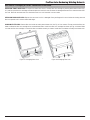
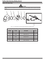
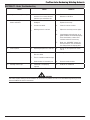
SECTION 8: Changing of Cover Lenses and Filter Lens
REPLACING FRONT COVER LENS: To replace the front cover lenses, remove filter lens cartridge by moving locks toward centre (Fig.
8-1) and lift up the filter lens cartridge to remove/replace the front lens cover. Remove the damaged front cover lens from the front cover
lens seal. Reinstall new front cover lens into front cover lens seal. Assemble in reverse order.
REPLACING REAR COVER LENS: Replace the rear cover lens if it is damaged. Place your fingernail in recess below the viewing area and
flex lens upwards until it releases from both edges.
CHANGING FILTER LENS: Remove filter lens holder assembly from helmet shell. See Fig. 8-1 for removal. Flex top end of the filter lens
holder to allow for filter lens cartridge to be removed from frame. Install new filter lens cartridge into frame per Fig. 8-2 below. Make
sure that the filter lens cartridge is inserted in filter lens holder correctly as shown. Install filter lens holder assembly into helmet shell.
Art # A-11795
Art # A-11796
Figure 8-1 Changing Cover Lens
Figure 8-2 Changing Filter Lens

ProPlus Auto-Darkening Welding Helmets
18 Manual 0-5276
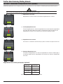
SECTION 9: ProPlus Digital Auto-Darkening Filter Lens Controls
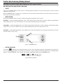
ON/ MODE BUTTON AND BATTERY INDICATOR
• ON-OFF
Shortly press ON/MODE button to check if the lens is working properly and begin to set up lens shade number, sensitivity, and delay
adjustments (See Fig. 9-1A).
When the ON/MODE button is long pressed (3 seconds), the lens will power off, and return to the clear state. Do not use the helmet if
the lens does not function as described.
• MODECONTROL
Shortly press ON/MODE button to select the mode for the appropriate application (See Fig. 9-1A):
Weld Mode − used for most welding applications. Push “FUNC” button to adjust shade number, sensitivity, and delay settings properly
before welding (See Fig. 9-1C).In this mode the lens turns to dark immediately when you start welding.
Cutting Mode − used for cutting applications. Push “FUNC” button to adjust shade number, sensitivity, and delay settings properly before
cutting (See Fig. 9-1C).In this mode the lens turns to dark immediately when you start cutting (See Fig. 9-1C).
Grind Mode − used for grinding applications. In this mode the lens shade is fixed shade No. 4. Can not adjust shade number, sensitivity,
and delay settings (See Fig. 9-1C).
Art # A-11797
Figure 9-1 ON/MODE Button
• BATTERYINDICATOR
The symbol “ “ shows the current state of the battery (See Fig. 9-1B). The capacity of batteries is displayed by three bars(See Fig.
9-2). The symbol “ “ appears on the display screen before 1−2 days of battery life remaining. Replace with 2 x CR2450 Lithium
batteries. The Battery Indicator is not in real-time, but should be updated after shortly pressing ON/MODE button.
6
Art # A-11798
Figure 9-2 Battery Indicator

ProPlus Auto-Darkening Welding Helmets
Manual 0-5276 19
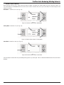
• VARIABLESHADECONTROL
After turning on the lens, press “FUNC” button to choose “SHADE”, and adjust lens shade number (See Fig. 9-3/9-4/9-5: A&B). Use
the shade control UP and DOWN buttons to select the lens shade in the dark state (See Fig. 9-3/9-4: C&D). The shade range for each
mode are as below:
Weld Mode − Shade No. 8-13 (See Fig. 9-3)
7a
Art # A-11799
Figure 9-3 Variable Shade Control- Weld Mode
Cutting Mode −Shade No. 5-8 (See Fig. 9-4)
7b
Art # A-11800
Figure 9-4 Variable Shade Control- Cutting Mode
Grind Mode −Shade No. 4 only (See Fig. 9-5)
Art # A-11801
Figure 9-5 Variable Shade Control- Grind Mode
Select the proper shade number for your welding/cutting process, by referring to “Table 4-1 Recommended Protective Filters for Electric
Welding”.

ProPlus Auto-Darkening Welding Helmets
20 Manual 0-5276
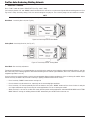
• SENSITIVITYCONTROL
Press “FUNC” button to choose “SENSITIVITY”(See Fig. 9-6/9-7: A&B).
Use Sensitivity Control “UP” and “DOWN” buttons to make the lens more or less sensitive to arc light of different welding processes (See
Fig. 9-6/9-7: C&D). Sensitivity setting 5-10 is the normal setting for everyday use. The sensitivity ranges for each mode are as below:
NOTE
A lens sensitivity of 10 turns the lens permanently dark.
Weld Mode − Sensitivity No. 0-10 (See Fig. 9-6)
8a
Art # A-11802
Figure 9-6 Sensitivity Control- Weld Mode
Cutting Mode −Sensitivity No. 0-10 (See Fig. 9-7)
8b
Art # A-11803
Figure 9-7 Sensitivity Control- Cutting Mode
Grind Mode −No sensitivity adjustment
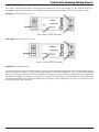
For optimum performance, it is recommended to set sensitivity to the maximum at the beginning and then gradually reduce it, until the
filter reacts only to the welding light flash and without flickering due to ambient light conditions (direct sun, intensive artificial light,
neighbouring welder’s arcs etc.).
It may be necessary to adjust helmet sensitivity to accommodate different lighting conditions or if lens is flashing On and Off. Adjust
helmet sensitivity as follows: Adjust helmet sensitivity in lighting conditions helmet will be used in.
• Press Sensitivity “DOWN” button to lower setting to 0.
• Face the helmet in the direction of use, exposing it to the surrounding light conditions.
• Press Sensitivity “UP” button repeatedly until the lens darkens, then press “DOWN” button until lens clears. Helmet is ready for
use. Slight readjustment may be necessary for certain applications or if lens is flashing on and off.
• When sensitivity is set level 10, the lter will remain dark for special welding application under both WELD MODE and CUTTING
MODE. With this setting, the welding helmet will NOT automatically turn off after half an hour not use.
Page is loading ...
Page is loading ...
Page is loading ...
Page is loading ...
-
 1
1
-
 2
2
-
 3
3
-
 4
4
-
 5
5
-
 6
6
-
 7
7
-
 8
8
-
 9
9
-
 10
10
-
 11
11
-
 12
12
-
 13
13
-
 14
14
-
 15
15
-
 16
16
-
 17
17
-
 18
18
-
 19
19
-
 20
20
-
 21
21
-
 22
22
-
 23
23
-
 24
24


CIGWELD ProPlus+® Digital Auto-Darkening Welding Helmet User manual
- Category
- Bicycle accessories
- Type
- User manual
Ask a question and I''ll find the answer in the document
Finding information in a document is now easier with AI
Related papers
-
ESAB ProLite® Auto-Darkening Welding Helmet User manual
-
-
-
-
CIGWELD WeldSkill 205ACDC Operating instructions
-
-
CIGWELD WeldSkill 155 Operating instructions
-
-
-
CIGWELD Proguard Operating instructions
Other documents
-
 Antra Digital Diamond Series User manual
-
Performax AntFi X60-2 User manual
-
 ATD Tools ATD-3721 User manual
-
Lincoln Electric VIKING 2450D Operating instructions
-
METAL MAN ATEC8735SGC User manual
-
 Antra AH7-X30P User manual
-
Miller ULTRA HDV AUTO-DARKENING HELMET Owner's manual
-
-
-
 METAL MAN ABB8700SGC User manual


