Page is loading ...

2014
Made in China
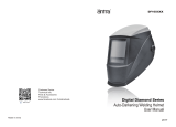
Auto-Darkening Welding Helmet
FOR SKU#:2421487
User's Manual

USER INSTRUCTION MANUAL
AUTO-DARKENING WELDING HELMET
2014
WARNING
Please read all instructions before using this Auto-Darkening Welding Helmet.
GENERAL INFORMATION
This Auto-Darkening Welding Helmets DOES NOT protect against severe
impact hazards, such as broken grinding wheels or abrasive discs, explosive
devices or corrosive liquids. Machine guards or eye splash protection must
be used when these hazards ate present.
The auto-darkening welding filter is suitable for all Arc welding processes
such as MIG, MAG, TIG, SMAW, Plasma Arc, and Carbon Arc.
This auto-darkening welding helmet is NOT recommended for “Overhead”
welding applications, Laser welding or Laser cutting applications.
In the event of electronic failure, the welder remains protected against UV
and IR radiation according to shade 16.
The auto-darkening welding filter should always be used with original inner
and outer cover lenses.
We are not responsible for any failure due to modifications of the welding.
Protection can be seriously impaired if unapproved modifications are made.
-1-
TECHNICAL SPECIFICATIONS
-2-
ADF Model
UV/IR Protection
Light State
Dark State
Shade Control
Sensors
Grinding
Sensitivity Control
Reaction Time
Dark to Light
Solar Cell
Battery Measurement
Power On/Off
Argon Arc Welding Current Level
Inner Cover Lens
Operation Temp
Storage Temp
Weight
0.1-1.0 Seconds Continuously Adjustable
2 x CR 2032 ( Replaceable)
Yes
> 5Amp
99.3 x 45.4 x 1.0mm
-20°C to +70°C (-4° F to 158° F)
508g
AntFi X60-2
98mm x 42mm/3.86" x1.65"
110 x 90 x9mm /4.33" x 3.54" x 0.35"
External
Fully Automatic
-10°C to +55°C (14° F to 131° F)
Knob Adjustable
0.00004 Sec (1/25,000)
Yes
Battery Type
Permanent Shade DIN 16
Shade DIN 4
Shade DIN 4
4
Viewing Area
Cartridge Size
Standards EN379 CE , ANSI Z87.1
2 Ranges: 4/5-9 and 4/9-13
Note: When stored in extremely cold temperature, the helmet should be
warmed up to ambient temperature before welding.
DO
Ensure the front cover lens is mounted before using and the protective film on
the lens cover is removed.
Ensure that the lens is clean and there is no dirt or spatter covering the 4
sensors at the front of the filter cartridge.
Inspect all parts for signs of wear or damage. Any scratched or cracked parts
should be replaced prior to use.
DON’T
NEVER place the helmet on a hot surface.
NEVER open or tamper with the filter cartridge.

Two ranges of shade numbers, 5-9 and 9-13 are available in the dark
state.(Fig.1)
2. ON/OFF
The solar unit automatically switches ON when exposed to light.
3.SELECT THE SHADE NUMBER
ATTENTION!!
MAKE SURE that the Shade Adjustment Knob is on the ''5(9)-9(13)'' position,
NOT on ''GRIND'' position, before starting to weld.
-3-
Shade Adjustment Knob
(Fig.1)
Shade Range Select Switch
1
The ranges can be selected by the Shade Range Select Switch as shown on
Fig.1.
If the Shade Selection Switch is on the ''5-9'' position, then the shade selection
on the Shade Adjustment Knob is from 5-9 (MIN-MAX).
If the Shade Selection Switch is on the ''9-13'' position, then the shade
selection on the Shade Adjustment Knob is from 9-13(MIN-MAX).
Once the Shade Range is selected, the shade number can be adjusted by
turning the Shade Adjustment Knob. The arrow of the knob indicates the shade
setting.
Set the Adjustment Knob to ''GRIND'' position for grinding applications. the
filter will stay at Shade Number 4 and will not react to any welding arcs.
MAKE SURE TO RESET the knob back to ''“5-9/9-13” position (NON-GRIND
mode) after grinding.
-4-
RECOMMENDED SETTINGS
9
876 10
Shade 8
Shade 5
Shade 9 Shade 10
Shade 11 Shade 12 Shade 13 Shade 14 Shade 15
Shade 11 Shade 12 Shade 13 Shade 14
Shade 12 Shade 14
Shade 15
Shade 11
Shade 13Shade 12Shade 11Shade 10 Shade 14
REFERENCE ANSI Z49.1-2005
OPERATION
1.ADJUST THE WELDING HELMER ACCORDING TO YOUR INDIVIDUAL
REQUIREMENTS
The headband should be adjusted both in circumference and height.
The angle between face and helmet should also be adjusted and recommended
to be 10°-12°.

4. DELAY TIME (Fig.2)
This Welding Helmet is featured with continuously adjustable delay time
control. The lens will lighten in 0.1 to 1.0 seconds upon ambient temperature
and shade setting. By turning the DELAY knob (on the rear of the cartridge)
clockwise, the delay time will increase from 0.1 seconds to 1.0 seconds.
Turn Knob counterclockwise for tack welding or production welding with short
welds. Turn Knob clockwise for welding at high amperage where there is an
after glow from the welding.
-5-
5. SELECT SENSITIVITY (Fig.3)
This welding helmet features continuously adjustable sensitivity control.
Sensitivity control knob is used to adjust how sensitive the auto darkening filter
reacts to the welding arc:
Turn the knob (on the back of the cartridge) clockwise when used for low
amperage welding (or stable ARC like DC-TIG), and the filter will become more
sensitive to welding arc.
Turn the knob counter-clockwise when used in brighter conditions except
for welding process that has very stable ARC like DC TIG, and the filter will
become less sensitive to welding arc.
NOTE: For DC-TIG applications, close to MAX positions of SENSITIVITY and
DELAY may be required according to your TIG amperage and welding
environment.
(Fig.2)
2
6.MEASUREMENT(Fig.4)
Battery Measurement
Press the button “Batt.”. If the LED does not light, you need to replace the
batteries.
Note: Do Not Use the helmet under condition of fault(or defective).
The lenses will turn dark when you press the button “Batt.” in Welding
Mode.
-6-
(Fig.4)
LED “Batt.” Buttion
(Fig.3)
3

-8-
Make sure that the protective film is removed from the new cover lens. Place the
new cover lens in the recess at the front of the helmet. (Fig.7)
(Fig.7)
Replacement of inner cover lens:
To remove the inner cover lens, pulling out the top edge. (Fig.8)
(Fig.8)
Take out the old cover lens. (Fig.6)
(Fig.6)
-7-
PARTS LIST
1
Helmet Shell
2
Adjustable Knob
3
Front Cover Lens
4
Cartridge
5
Inside Cover Lens
6
Lens Retaining Frame
8
Adjustable Headband
7
Lock Switch
MAINTENANCE
Remove the front lens by pulling out the retaining frame by move the lock
switch from the helmet. (Fig.5)
(Fig.5)
Note: Do Not Use the helmet without the cover lens in place.

Insert tabs of the back lens retaining frame under the two slots of the helmet.
Push the lock switch until it snaps into right place. (Fig.12)
(Fig.12)
WARNING! Do not use the helmet and lens unless they are fully assembled.
Install
Insert tabs of the front lens retaining frame under the two slots of the back lens
retaining frame. Push the two corners on front lens retaining frame until it
snaps into place. (Fig.11)
(Fig.11)
-10-
The new inner cover lens is assembled after the protective film is removed.
Locate one of the sides inserting the edge under the hook at the side and bend
the lens in the middle part and locate the lens under the hook at the other side.
(Fig.9)
-9-
(Fig.9)
Replacement of batteries:
Carefully open battery compartments. Always replace both batteries at the
same time. The compartments snap close. (Fig.10)
(Fig.10)
+
+

OPERATION
Adjust headband per personal preference. (Fig.13)
Adjust helmet/headband stop to get desired viewing angle. (Fig.14)
(Fig.13) (Fig.14)
-11 -
Insert the magnifying lens. (Fig.15)
(Fig.15)
-12-
INSPECTION
1. Carefully inspect your Auto-Darkening Welding Filter regularly.
2. Cracked, pitted or scratched filter glass or cover lenses reduce vision will
seriously impair protection.
3. These should be replaced immediately to avoid injury to the eyes.
4. Inspect the helmet frequently and replace worn or damaged parts.
CLEANING
Clean the helmet with mild soap and lukewarm water.
Clean the welding filter with a clean lint-free tissue or cloth,
Do not immerse in water.
Do not use solvents.
TROUBLE SHOOTING
IRREGULAR DARKENING
Headband has been set unevenly so the distance between the eyes and the
lens is different from the left to the right side.
AUTO DARKENING FILTER DOES NOT DARKEN OR FLICKERS
Make sure that the adjustment knob is on "5-9/9-13" position.
Front cover lens is soiled, clean or replace it.
Photo sensors are dirty, wipe them clean with a soft lint-free cloth.
Welding current is too low, select the slow position on the filter and ensure the
view of the weld is unobstructed.
Change to high sensitivity.
Replace the two Lithium Batteries.
POOR VISION
Ensure the cover lens and the filter cartridge is clean.
Ensure the shade number is correct and adjust accordingly.
Ensure ambient light is not too low.

-13 -
WARRANTY
The passive welding helmets are warranted against defects in materials and
workmanship for a period of two (2) year from date of purchase.
This warranty is limited to the repair or replacement of items which are not in
compliance with this warranty. This warranty does not extend to any item
subject to unauthorized repair, alteration, tampering, improper storage or
operation, inadequate maintenance, accident, misuse, abuse or negligent
handling. This warranty is not transferrable from the original purchaser to any
subsequent purchaser.
Seller shall in no event be liable or responsible for any injury, damage or loss
resulting either directly or indirectly from, the use or misuse of this product.
This limited warranty is the exclusive remedy of purchaser and the sole
obligation of Seller in connection with any claim, whether in contract,
negligence, strict liability, tort or otherwise.
Do not use these items unless you are trained and experienced in the proper
use and maintenance. Please read the instruction manual carefully to avoid
certain situations which may void this limited warranty.
/