Page is loading ...

• Sales and Service through Subsidiaries and Distributors Worldwide •
Cleveland, Ohio 44117-1199 U.S.A. TEL: 216.481.8100 FAX: 216.486.1751 WEB SITE: www.lincolnelectric.com
• World's Leader in Welding and Cutting Products •
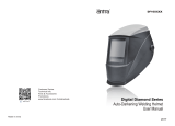
VIKING™
2450D SERIES
AUTO-DARKENING HELMETS
4.50
x
5.25 STANDARD REPLACEMENT LENS
OPERATOR’S MANUAL
IM10131
October 2013
Copyright © Lincoln Global Inc.
TABLE OF CONTENTS Page
SAFETY WARNINGS – READ BEFORE USING 1
HELMET INFORMATION 2
SPECIFICATIONS 3
OPERATING INSTRUCTIONS 4
CARTRIDGE OPERATIONS/FEATURES 5 thru 7
HELMET CARE AND MAINTENANCE 8
SHADE GUIDE SETTINGS 8
CARTRIDGE AND LENS REPLACEMENT 9
TROUBLESHOOTING 10
WARRANTY INFORMATION 11
REPLACEMENT PARTS 11
GRAPHICS MAY VARY

• Sales and Service through Subsidiaries and Distributors Worldwide •
Cleveland, Ohio 44117-1199 U.S.A. TEL: 216.481.8100 FAX: 216.486.1751 WEB SITE: www.lincolnelectric.com
• World's Leader in Welding and Cutting Products •
VIKING™
2450D SERIES
AUTO-DARKENING HELMETS
4.50
x
5.25 STANDARD REPLACEMENT LENS
OPERATOR’S MANUAL
IM10131
October 2013
Copyright © Lincoln Global Inc.
TABLE OF CONTENTS Page
SAFETY WARNINGS – READ BEFORE USING 1
HELMET INFORMATION 2
SPECIFICATIONS 3
OPERATING INSTRUCTIONS 4
CARTRIDGE OPERATIONS/FEATURES 5 thru 7
HELMET CARE AND MAINTENANCE 8
SHADE GUIDE SETTINGS 8
CARTRIDGE AND LENS REPLACEMENT 9
TROUBLESHOOTING 10
WARRANTY INFORMATION 11
REPLACEMENT PARTS 11
GRAPHICS MAY VARY

HELMET INFORMATION
This Auto-Darkening Welding Helmet will change from a light state (shade 4)
to a dark state (Shade 5-13) when arc welding starts.
The filter automatically returns to a light state when the arc stops.
Match your welding application to the shade indicated on the shade chart.
(See Page 8)
• Operating temperature: 14°F ~ 131°F (-10°C ~ 55°C).
• Do not use or open the auto-darkening filter if damaged by shock, vibra-
tion or pressure.
• Keep the sensors and solar cell clean. Clean the filter cartridge using a
soapy water solution and soft cloth which should be damp but not saturat-
ed.
This Auto-Darkening Welding Helmet is designed for use with GMAW, GTAW,
MMAW welding, or Plasma Arc and air carbon arc cutting. This helmet also
has cutting and grinding modes.
The cartridge provides protection from harmful UV and IR radiation, in both
dark and light states.
The cartridge contains four sensors to detect the light from the welding arc,
resulting in the lens darkening to a selected welding shade.
• Do not use solvents or abrasive cleaning detergent.
• If cover lens is spattered or covered with dirt, it should be replaced imme-
diately.
• Use only replacement parts specified in this manual.
• Do not use the helmet without inside and outside cover lenses properly
installed.
• Do not use helmet if lens does not function as described.
2
SAFETY WARNINGS – READ BEFORE USING
ARC Rays can injure eyes and burn skin
• Before welding, always inspect helmet and filter lens to be sure they are fitted
properly, in good condition and not damaged.
• Check to see that the clear lens is clean and securely attached to the helmet.
• Always wear safety glasses or goggles under the welding helmet and protective
clothing to protect your skin from radiation, burns and spatter.
• Ensure that optical radiation from other welderʼs arcs in the immediate area
does not enter in from behind the helmet and auto-darkening filter.
Note:
Auto-darkening filters in Lincoln helmets are designed to protect the user against harmful
ultra-violet and infrared rays both in the dark and light states. No matter what shade the filter is
set to, the UV/IR protection is always present.
FUMES AND GASES can be dangerous to your health.
• Keep your head out of fumes.
• Use enough ventilation or exhaust at the arc or both to keep fumes and gases
from your breathing zone and general area.
• When welding with electrodes which require special ventilation such as
stainless or hard facing (see instructions on container or MSDS) or on
lead or cadmium plated steel and other metals or coatings which pro-
duce highly toxic fumes, keep exposure as low as possible and within
applicable OSHA PEL and ACGIH TLV limits using local exhaust or
mechanical ventilation. In confined spaces or in some circumstances,
outdoors, a respirator may be required. Additional precautions are also
required when welding on galvanized steel.
1
WARNING
Refer to http://www.lincolnelectric.com/safety
for additional safety information.

SPECIFICATIONS
1)
Headgear compliance with ANSI Z87.1 is without sweatband installed.
3
OPERATING INSTRUCTIONS
Headgear Adjustment
HEAD SIZE ADJUSTMENT: HEADGEAR TIGHTNESS is adjusted by push-
ing in the Ratchet Knob and turning to adjust for the desired head size. This
knob is located at the back of the helmet. HEADGEAR CROWN ADJUST-
MENT is made by adjusting for comfort and snapping the pins into the holes
to lock securely in place.
TILT: Tilt adjustment is located on the right side of the helmet. Loosen the
right headgear tension knob and push the top end of the adjustment lever
outward until the leverʼs Stop Tab clears the notches. Then rotate the lever
forward or back to the desired tilt position. The Stop will automatically
engage again when released locking the helmet into position.
FORE / AFT ADJUSTMENT: Adjusts the distance between the userʼs face
and lens. To adjust, loosen the outside tension knobs and slide forward or
back to desired position and retighten. NOTE: Make sure both sides are
equally positioned for proper operation.
4
Crown
Adjustment
Ratchet
Knob
Fore-Aft
Adjustment
Tilt
Adjustment
Optical Class
LCD Viewing Area
Cartridge Size
Arc Sensor
Light State
Grind State
Cutting Shades
Variable Welding Shades
Shade Control
Power On/Off
Sensitivity Control
UV/IR Protection:
Power Supply:
Battery
Light to Dark Switching Time
Dark to Light Switching Time
Oxyfuel Gas Welding
Oxygen Cutting
Grinding:
TIG Rating
Operating Temperature
Storage Temperature
Compliance¹
1/1/1/1
97 x 62mm (3.82 x 2.44in.)
114 x 133mm (4.50 x 5.25in.)
4
DIN 4
DIN 4
5 to 8
9 to 13
Variable Shade, Digital Display Control
Auto-ON, Auto-OFF
Variable 0 to 10, Digital Display Control
Up to Shade DIN16 at all times
Solar cell with battery assist
2×CR2450 lithium batteries
0.00004 sec. (1/25,000sec.)
Variable 0 to 10, Digital Display Control
(0.1 sec. to 1.0 sec.)
Yes
Yes
Yes
DC ≥ 2 amps AC ≥ 2 amps
14°F ~ 131° F (-10°C ~ +55°C)
-4°F ~ 158° F (-20°C ~ +70°C)
ANSI Z87.1-2010/CSA Z94.3/CE EN379

CARTRIDGE OPERATION/FEATURES
ON/MODE BUTTON AND BATTERY INDICATOR (See Fig-1 and Fig-2)
• ON-OFF (Lens will automatically darken when arc is present)
The Shade Cartridge will automatically turn on, the digital display control will activate and
helmet will be ready for use. It is recommended that the user review helmet settings
prior to use. The welding helmet will automatically turn off after one half hour of no use.
• MODE CONTROL
Short press of the ON/MODE button to select the mode appropriate for the work activity
(See Item A):
Weld Mode − used for most welding applications. Push "FUNC" button to adjust shade
number, sensitivity, and delay settings before welding (See Item C).In this mode, the lens
turns to dark immediately when you start welding.
Cutting Mode − used for cutting applications. Push "FUNC" button to adjust shade
number, sensitivity, and delay settings before cutting (See Item C).In this mode the lens
turns to dark immediately when you start cutting (See Item C).
Grind Mode − used for grinding applications. In this mode the lens shade is fixed shade
No. 4. Shade number, sensitivity, and delay settings cannot be adjusted when in grind
mode (See Item C).
• BATTERY INDICATOR
The symbol " " shows the current state of the battery (See Item B). The volume
of batteries has four level symbols (See Fig-2). The symbol " " appears on the
display screen before 1 to 2 days of battery life remains, CR2450 lithium batteries
should be replaced at this time. The symbol of the Battery Indicator is not real-time
and is updated shortly after pushing the ON/MODE button.
• VARIABLE SHADE CONTROL
After turning on the lens, press the "FUNC" button to choose “SHADE”, adjust lens
shade number (See Fig-3,-4,-5, Items A and B). Use the shade control UP and
DOWN buttons to select the lens darkened state (See Fig-3,-4,-5, Items C and D).
The shade range for each mode is as follows:
5
A
B
FIG-1
FIG-2C
Weld Mode − No. 9 ~ No. 13 (See Fig-3)
Cutting Mode − No. 5 ~ No. 8 (See Fig-4)
Grind Mode - No. 4 only (See Fig-5)
• SENSITIVITY CONTROL
Press "FUNC" button to choose "SENSITIVITY" (See Fig-6,-7, Items A and B). Use
Sensitivity Control "UP" and "DOWN" buttons to make the lens more or less sensitive to
arc light for different welding processes (See Fig-6,-7, Items C and D). Sensitivity set-
tings 5 through 9 are the normal settings for everyday use. The sensitivity ranges for
each mode are as follows:
Weld Mode − No.0 ~ No. 10 (See Fig-6)
Cutting Mode - No.0 ~ No. 10 (See Fig-7)
Grind Mode − No sensitivity adjustment
6
A
B
C
FIG-3
D
A
B
C
FIG-4
D
A
B
C
FIG-5
D
A
B
C
FIG-6
D
A
B
C
FIG-7
D

HELMET CARE AND MAINTENANCE
Cleaning: Clean helmet by wiping with a soft cloth. Clean cartridge surfaces
regularly. Do not use strong cleaning solutions. Clean sensors and solar cells
with soapy water solution and a clean cloth and wipe dry with a lint-free cloth.
Do NOT submerge shade cartridge in water or other solution.
Storage: Store in a clean, dry location.
SHADE GUIDE SETTINGS
If your helmet does not include any one of the shades referenced above, it is
recommended you use the next darker shade.
8
NT 1
GUIDE FOR SHADE NUMBERS
OPERATION ELECTRODE SIZE ARC MINIMUM SUGGESTED
(
1
)
1/32 in. (mm) CURRENT (A) PROTECTIVE SHADE NO.
SHADE (COMFORT)
Shielded metal arc Less than 3 (2.5) Less than 60 7 –
welding 3-5 (2.5–4) 60-160 8 10
5-8 (4–6.4) 160-250 10 12
More than 8 (6.4) 250-550 11 14
Gas metal arc Less than 60 7 –
welding and flux 60-160 10 11
cored arc welding 160-250 10 12
250-500 10 14
Gas tungsten arc Less than 50 8 10
welding 50-150 8 12
150-500 10 14
Air carbon (Light) Less than 500 10 12
Arc cutting (Heavy) 500-1000 11 14
Plasma arc welding Less than 20 6 6 to 8
20-100 8 10
100-400 10 12
400-800 11 14
Plasma arc cutting (Light
)
(2)
(2)
(2)
Less than 300 8 9
(Medium) 300-400 9 12
(Heavy) 400-800 10 14
Torch brazing – – 3 or 4
Torch soldering – – 2
Carbon arc welding – – 14
PLATE THICKNESS
in. mm
Gas
welding
Light Under
1/8 Under 3.2 4 or 5
Medium 1/8 to 1/2 3.2 to 12.7 5 or 6
Heavy Over 1/2 Over 12.7 6 or 8
Oxygen cutting
Light Under 1 Under 25 3 or 4
Medium 1 to 6 25 to 150 4 or 5
Heavy Over 6 Over 150 5 or 6
(1)
As
a
rule
of thumb, start with a shade that is too dark, then go to a lighter shade which gives sufficient view of the weld zone without going
below the
minimum. In oxyfuel gas welding or cutting where the torch produces a high yellow light, it is desirable to use a filter lens that absorbs
the
yellow or
sodium line the visible light of the (spectrum) operation
(2)
These values apply where the actual arc is clearly seen. Experience has shown that lighter filters may be used when the arc is hidden by the
workpiece.
.
Data from ANSI Z49.1-2005
It may be necessary to adjust helmet sensitivity to accommodate different lighting condi-
tions or if lens is flashing On and Off. Adjust helmet sensitivity in lighting conditions hel-
met will be used in. Adjust helmet sensitivity as follows:
• Press the “DOWN” button to lower setting to 0.
• Face the helmet in the direction of use, exposing it to the surrounding light conditions.
• Press the “UP” button repeatedly until the lens darkens, then press the “DOWN” but-
ton until lens clears. Helmet is ready for use. Slight readjustment may be necessary
for certain applications or if lens is flashing on and off.
• DELAY CONTROL
Press "FUNC" button to choose "DELAY", begin lens delay adjustments (See Fig-8,
-9, Items A and B). Use the Lens Delay Control "UP" and "DOWN" buttons to adjust
the time for the lens to switch to the clear state after welding or cutting. (See Fig-8,-9,
Items C and D).
Weld Mode − No.0 ~ No. 10 (See Fig-8)
Cutting Mode - No.0 ~ No. 10 (See Fig-9)
Grind Mode − No delay adjustment
The delay is particularly useful in eliminating bright after-rays present in higher amper-
age applications where the molten puddle remains bright momentarily after welding. Use
the Lens Delay Control buttons to adjust delay from 0 to 10 (0.1 to 1.0 second). When
welding ceases, the viewing window automatically changes from the darkened state
back to light state but with a pre-set delay to compensate for any bright afterglow on the
work piece. The delay time/response can be set from Level 0 to level 10. It is recom-
mended to use a shorter delay with spot welding applications and a longer delay with
applications using higher currents. Longer delays can also be used for low current TIG
welding in order to avoid the filter opening when the light path to the sensors is tem-
porarily obstructed by a hand, torch, etc.
7
A
B
C
FIG-8
D
A
B
C
FIG-9
D

CARTRIDGE AND LENS REPLACEMENT
Replacing Front Clear Cover Lens: Replace the front cover lens if it is dam-
aged. Remove ADF holder assembly per Figure 1. Remove front cover lens from
helmet assembly. Carefully remove gasket from cover lens. Install new cover
lens into gasket and assemble to helmet shell. Make sure to assemble cover
lens and gasket into helmet shell the same way as it was removed.
Replacing Inside Clear Lens: Replace the inside clear lens if it is damaged.
Place your fingernail in recess below cartridge view window and flex lens
upwards until it releases from edges of cartridge view window.
Change the Shade Cartridge: Remove ADF holder assembly from helmet shell.
See figure 1 for removal. Flex top end of the ADF holder to allow for ADF car-
tridge to be removed from frame. Install new ADF cartridge into frame per figure
2 below. Make sure that the ADF cartridge is inserted in ADF holder correctly as
shown. Install ADF holder assembly into helmet shell.
INSTALLING AN AFTERMARKET MAGNIFYING LENS:
Simply slide the magnifying lens into the short rail located on the sides of ADF
holder per Figure 3.
9
Figure 3
Figure 1 Figure 2
SOLUTION
Clean or replace front cover lens.
Clean the Auto-Darkening car-
tridge with soapy water solution
and soft cloth.
Adjust sensitivity to required level.
Clean or replace front cover lens.
Check for cracked or pitted front
cover lens and replace as
required.
Make sure you are not blocking the
sensors or solar panels with your arm
or other obstacle while welding.
Adjust your position so that the sen-
sors can see the weld arc.
Make sure proper shade is selected.
Adjust sensitivity to required
level.
Adjust delay time to required
level.
Replace front cover lens
as needed.
POSSIBLE CAUSE
Front cover lens dirty.
Cartridge dirty.
Sensitivity is set too low.
Front cover lens dirty.
Front cover lens is damaged.
Sensors are blocked or Solar
panel is blocked.
Grind Mode Selected
Sensitivity set too high.
Delay time set too high.
Missing, damaged,
broken, cracked or
distorted front cover
lens.
TROUBLESHOOTING GUIDE
T
est your shade cartridge prior to welding by directing the front of the cartridge
toward a bright source of light. Then, using your fingers, rapidly cover and uncov-
er the sensors. The cartridge should darken momentarily as the sensor is
exposed. A torch striker can also be used.
10
PROBLEM
Difficult to see through filter.
Filter does not darken when
arc is struck.
Filter darkening without arc
being struck.
Filter remains dark after
completing a weld.
ADF is
cracked.
Weld spatter
is damaging
the filter.
WARNING
Cease (STOP) using this product if this prob-
lem exists. UV/IR protection may be compro-
mised resulting in burns to the eyes and skin.

WARRANTY INFORMATION
WARRANTY INFORMATION: Reference IMWS1 included in Literature.
SPATTER DAMAGE IS NOT COVERED BY WARRANTY:
Do not use this product without the correct protective clear lenses installed properly
on both sides of the Auto-Darkening Filter cartridge (ADF). The clear lenses supplied
with this helmet are properly sized to work with this product and substitutions from
other suppliers should be avoided.
REPLACEMENT PARTS
*Not illustrated
11
3
2
7
1
8
6
4
ITEM
1
2
3
4
5*
6
7
8
QTY
1
1
1
1
1
1
1
1
PART NO.
KP2898-1
KP3243-2
KP2931-1
KP3908-1
KP2930-1
S27978-31
S27978-32
S27978-33
DESCRIPTION
OUTSIDE CLEAR LENS
(PKG. QTY: 5)
ADF CARTRIDGE
INSIDE CLEAR LENS
(PKG. QTY: 5)
HEADGEAR ASSEMBLY
(INCLUDING SWEATBAND)
SWEATBAND (PKG. QTY: 2)
REPLACEMENT SHELL
OUTSIDE CLEAR LENS SEAL
ADF HOLDER
• Sales and Service through Subsidiaries and Distributors Worldwide •
Cleveland, Ohio 44117-1199 U.S.A. TEL: 216.481.8100 FAX: 216.486.1751 WEB SITE: www.lincolnelectric.com
• World's Leader in Welding and Cutting Products •
QTY
1
1
1
1
1
1
1
1
PART NO.
KP3046-100
KP3046-125
KP3046-150
KP3046-175
KP3046-200
KP3046-225
KP3046-250
KP3047-1
DESCRIPTION
CHEATER LENS 1.00 MAGNIFICATION
CHEATER LENS 1.25 MAGNIFICATION
CHEATER LENS 1.50 MAGNIFICATION
CHEATER LENS 1.75 MAGNIFICATION
CHEATER LENS 2.00 MAGNIFICATION
CHEATER LENS 2.25 MAGNIFICATION
CHEATER LENS 2.50 MAGNIFICATION
HARD HAT ADAPTER
OPTIONAL ACCESSORIES
/