
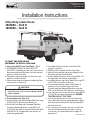
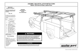
1
Installation Instructions
Utility Body Ladder Racks
1501250 – 13.5 ft
1501260 – 14.5 ft
—continued inside
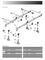
1. Verify Rack Will Fit Your Truck Body – Fig. 1
A. DETERMINE WHERE THE RACK WILL BE
MOUNTED. Depending on your truck, the rack may
be mounted on top of the boxes, on front and rear
panels, or another location
B. Position the mounting angles on the truck in the
position it will be mounted
C. Measure the distance between the Mounting Feet
and record it as distance X.
AT LEAST TWO PEOPLE ARE
NECESSARY TO INSTALL THIS RACK
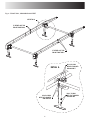
C. Assemble the Rear Crossbar to the Rear Rails
using the Latch Pins
D. Slide the Front Crossbar onto the Front Rails
E. Join the Front and Rear halves by sliding the Rear
Side Rails into the Front Side Rails
F. Install the Side Connector Plates using (6)M16 x 35
Carriage Bolts with washers and locknuts
G. Assemble the four Legs to the Side Rails using M12
x 55 HHCS with washers & locknuts
H. Lift and rotate the legs inward so the Rack can
stand by itself. Attach the Legs to the Front
Crossbar and Rear Mounting Brackets using the
M16 x 85 HHCS with (2) flat washers, and lock nuts
I. Insert the Feet into the Legs and attach using (8)M12
x 75 HHCS with washers and locknuts (FINGER
TIGHTEN ONLY AT THIS TIME)
J. If the distance between the Front and Rear Legs
(when adjusted to shortest point/position) is longer
than the measured distance X the Front Side Rails
will need to be cut
K. If it is necessary to shorten the rack, cut the Front
Rails by the determined amount now. If cutting
is necessary, you should paint the cut edges to
prevent rust.
www.buyersproducts.com
Phone (440) 974-8888
Fax 800-841-8003
CAUTION
CHECK TO ENSURE THAT THE MOUNTING LOCATIONS
CHOSEN ARE CLEAR OF ALL TAIL LIGHTS, WIRING, AND BOX
HANDLE HARDWARE
2. Preassemble Rack (Figs. 2-6)
A. Install the Rear Legs onto the Rear Side Rails using
M12x55 HHCS, flat washers and lock nuts.
B. Install the Driver Side and Passenger Side Rear
Crossbar Mounting Brackets using (2)M10 x 25
HHCS with lock washers to attach to the Rear Rails
and (2)M10 x 25 Carriage Bolts with locknuts to
attach the grab handle

2
WARNING
LADDER RACK IS RATED AT 1,000 LBS. DO NOT EXCEED
THIS LIMIT FOR ANY REASON AND NEVER EXCEED THE
GROSS VEHICLE WEIGHT RATING(GVWR) OR GROSS
AXLE WEIGHT RATING(GAWR) AS SET BY THE VEHICLE
MANUFACTURER.
WARNING
ALL PAYLOADS MUST BE SECURELY FASTENED FOR
TRANSPORTATION
WARNING
DO NOT CUT REAR SIDE RAILS FOR ANY REASON.
WARNING
NEVER USE THE LADDER RACK WITH THE REAR CROSS BAR
REMOVED. THIS WILL AFFECT THE STRUCTURAL INTEGRITY
OF THE RACK.
WARNING
USE CAUTION CARRYING A PAYLOAD ON THE LADDER RACK.
ALWAYS LOAD THE LADDER RACK AS LOW AND EVEN AS
POSSIBLE. ANY PAYLOAD CARRIED ABOVE THE FLOOR OF
THE TRUCK’S BED WILL INCREASE THE TENDENCY OF THE
VEHICLE TO ROLLOVER.
CAUTION
DOUBLE CHECK THAT THE HOLES ARE CLEAR OF ALL TAIL
LIGHTS, WIRING, BOX HANDLE HARDWARE AND THERE IS
ROOM TO MOUNT THE ANGLES
L. Set the preassembled rack onto the truck to verify
fit
M. After fit is verified, use predrilled holes in the Feet
to mark the places where mounting holes will need
to be drilled.
N. Remove rack and drill all necessary holes (For 1/2"
diameter hardware)
3. Final Installation – Fig. 4 and 6
NOTE: Silicone is provided to seal all joints and
prevent water from entering toolboxes and/or the
rack
A. Separate the Front and Rear halves of the rack,
apply silicone around the entire swaged surfaces of
the Rear Rails, and reconnect the halves.
B. Install the Connector Plates and (4)M16 x 35
Carriage Bolts with washers and locknuts.
C. Install the Front Hoop
a. Apply silicone to the swaged surfaces of the
Front Rails then slide the Front Hoop into position.
b. Use (2)M10 x 70 Carriage Bolts with washers &
locknuts to secure.
D. Install the Center Crossmember using (2)M12 x 75
HHCS with washers and locknuts
E. Position the Rack on the truck and attach using the
Angles and (8)M12 x 45 HHCS with washers and
locknuts
NOTE: The bottom of the feet have drain holes so if
any gasket tape is used between the bottom of the
Feet and the body of the truck the installer should
ensure that these drain holes remain uncovered
4. ALIGNING, MAINTENANCE, & WARNING
A. Aligning – Stand in front of the vehicle. Note the
alignment of the cab hoop in relation to the roof of
the truck cab. Have an assistant adjust the rack
to the left or right until the front hoop is centered
over the truck cab. The hardware that connects
the mounting foot to the leg can now be tightened.
Recheck alignment and adjust if necessary. All
hardware can now be fully tightened, starting with
the gusset points at the top of each leg.
B. Maintenance – Your Buyers ladder rack has a
powder coat finish and can be kept clean by using
a soft sponge or cloth with mild soap and water.

3
Fig. 1
Fig. 2 - REAR RAIL, CROSSBAR AND FEET
Distance "X"
M10 X 25 HHCS
WITH LOCK WASHER
M10 X 25 CARRIAGE
WITH LOCK NUT
M16 X 85 HHCS
WITH FLAT WASHERS
AND LOCK NUT
M12 X 75 HHCS
WITH FLAT WASHERS
AND LOCK NUT
M12 X 55 HHCS
WITH FLAT WASHER
AND LOCK NUT
LATCH PIN

4
Fig. 3 - FRONT RAIL, CROSSBAR AND FEET
SEE DETAIL A
DETAIL A
IF NEEDED, CUT THIS
END OF FRONT RAILS
IF NEEDED, CUT THIS
END OF FRONT RAILS
M12 X 75 HHCS
WITH FLAT WASHERS
AND LOCK NUT
M16 X 85 HHCS
WITH FLAT WASHERS
AND LOCK NUT
M12 X 55 HHCS
WITH FLAT WASHER
AND LOCK NUT

5
Fig. 4 - FRONT HOOP, SIDE CONNECTORS, MIDDLE CROSSBAR AND ANGLE MOUNTS
M16 X 35 CARRIAGE
WITH FLAT WASHER
AND LOCK NUT
M10 X 70 CARRIAGE
WITH FLAT WASHER
AND LOCK NUT
M12 X 45 HHCS
WITH FLAT WASHERS
AND LOCK NUT
M12 X 75 HHCS
WITH FLAT WASHER
AND LOCK NUT

6
Fig. 5 - PARTS
1
2
2
3
4
6
5
7
8
9
10
11
12
13
3
12
13
12
13
11
10
7
12
13
ITEM PART NO. QT Y. DESCRIPTION
1 3040866 1 FRONT HOOP
2 3040867 2 RAIL, SIDE, FRONT
3
3040868 2 RAIL, SIDE, REAR (for 1501250)
3040879 2 RAIL, SIDE, REAR (for 1501260)
4 3040869 1 CROSSBAR, FRONT
5 3040870 1 CROSSBAR, REAR
6 3040871 1 CROSSBAR,CENTER
7 3040523 4 PLATE, CONNECTOR, SIDE RAIL
Bills of Material
ITEM PART NO. QT Y. DESCRIPTION
8 3040524 1 BRACKET, CROSSBAR MOUNT, REAR DS
9 3040525 1 BRACKET, CROSSBAR MOUNT, REAR PS
10 3040872 2 LEG, PS
11 3040873 2 LEG, DS
12 3040874 4 FOOT ASSEMBLY
13 3040875 4 ANGLE, MOUNT, SUPPORT
- 3040876 1 HARDWARE KIT
- 3015981 1 SILICONE TUBE

7
Fig. 6 - ASSEMBLED RACK
Underneath View of Hardware and BracketOptional Mount Position

8
3040880_A
www.buyersproducts.com
Phone (440) 974-8888
Fax 800-841-8003
WARRANTY
Buyers Products Co. warrants all truck/trailer hardware
manufactured or distributed by it, to be free from defects in material
and workmanship for a period of one year from date of shipment.
Parts must be properly installed and used under normal conditions.
Any product which has been altered, including modification, misuse,
accident or lack of maintenance will not be considered under
warranty. Normal wear is excluded. The sole responsibility of
Buyers Products Co. under this warranty is limited to repairing
or replacing any part or parts which are returned, prepaid, and
are found to be defective by Buyers Products Co. Authorization
from Buyers Products Co. must be obtained before returning any
part. No charges for transportation or labor performed on Buyers’
products will be allowed under this warranty.
-
 1
1
-
 2
2
-
 3
3
-
 4
4
-
 5
5
-
 6
6
-
 7
7
-
 8
8


Buyers Products Company 1501250 User manual
- Type
- User manual
- This manual is also suitable for
Ask a question and I''ll find the answer in the document
Finding information in a document is now easier with AI
Related papers
-
Buyers Products Company 1701565 Installation guide
-
-
 Buyer's Products 1701005B Operating instructions
-
-
Buyers Products Company LT35 Owner's manual
-
-
-

Other documents
-
 Buyers Products 5562001 Owner's manual
-
Panasonic TX-43D302B 43 Inch Full HD Smart TV User manual
-
 Little Giant Ladders 15270-001 User guide
-
 Buyers Products Class 5 Hitch Receiver Owner's manual
-
PRO-SERIES 807240 User manual
-
 WEATHER GUARD 1225 Installation guide
-
 Great Day RR100LB Operating instructions
-
 Buyers Products 8591000 Installation guide
-
Rockville RCS52 Owner's manual
-


