Page is loading ...

1
READ THROUGH THIS MANUAL
BEFORE STARTING CONSTRUCTION.
IT CONTAINS IMPORTANT INSTRUCTIONS
AND WARNINGS CONCERNING THE
ASSEMBLY AND USE OF THIS MODEL.
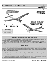
WEIGHT
30 –34 oz [850–964g]
WING LOADING
15.3 –17.2 oz/ft
2
[46.7–52.5 g/dm
2
]
RADIO
4-Channel minimum required
5–6 if optional aps/retracts are used
Tower
Hobbies
®
guarantees
this kit to be
free from defects
in both material and
workmanship at the
date of purchase. This
warranty does not cover any
component parts damaged by
use or modication. In no case shall
Tower Hobbies’ liability exceed the
original cost of the purchased kit. Further,
Tower Hobbies reserves the right to change
or modify this warranty without notice.
In that Tower Hobbies has no control over the nal
assembly or material used for nal assembly, no
liability shall be assumed nor accepted for any damage
resulting from the use by the user of the nal user-assembled
product. By the act of using the user-assembled product, the
user accepts all resulting liability.
If the buyer is not prepared to accept the liability associated with the
use of this product, the buyer is advised to return this kit immediately in
new and unused condition to the place of purchase.
To make a warranty claim send the defective part or item to Hobby Services at
the address below:
Hobby Services • 3002 N. Apollo Dr. Suite 1 • Champaign IL 61822 • USA
Include a letter stating your name, return shipping address, as much contact information as
possible (daytime telephone number, fax number, e-mail address), a detailed description of
the problem and a photocopy of the purchase receipt. Upon receipt of the package the problem
will be evaluated as quickly as possible.
WARRANTY
v1.1© 2016 Tower Hob bies .
®
A subsidiary of Hobbico, Inc.
®
®
TOWER HOBBIES
Champaign, Illinois
(217) 398-8970 ext. 6
WINGSPAN
40 in [1016 mm]
WING AREA
282 sq in [18.2 dm
2
]
LENGTH
34 in [ 864mm]
airsupport@hobbico.com
MKII EP Rx-R

2
As a new owner of an unmanned aircraft system (UAS), you
are responsible for the operation of this vehicle and the safety
of those around you. Please contact your local authorities
to nd out the latest rules and regulations.
In the United States, please visit:
knowbeforeyou y.org faa.gov/uas
AMA
We urge you to join the AMA (Academy of Model Aeronautics)
and a local R/C club. The AMA is the governing body of model
aviation and membership is required to y at AMA clubs.
Though joining the AMA provides many bene ts, one of the
primary reasons to join is liability protection. Coverage is not
limited to ying at contests or on the club eld. It even applies
to ying at public demonstrations and air shows. Failure to
comply with the Safety Code (excerpts printed in the back of
the manual) may endanger insurance coverage. Additionally,
training programs and instructors are available at AMA club
sites to help you get started the right way. There are over
2,500 AMA chartered clubs across the country. Contact the
AMA at the address or toll-free phone number below.
Academy of Model Aeronautics
5151 East Memorial Drive
Muncie, IN 47302-9252
Tele. (800) 435-9262
Fax (765) 741-0057
Or via the Internet at: www.modelaircraft.org
IMPORTANT: Two of the most important things you can do
to preserve the radio controlled aircraft hobby are to avoid
ying near full-scale aircraft and avoid ying near or over
groups of people.
SAFETY PRECAUTIONS
Protect Your Model, Yourself & Others…
Follow These Important Safety Precautions
1. Your Mustang should not be considered a toy, but rather a
sophisticated, working model that functions very much like
a full-size airplane. Because of its performance capabilities,
this model, if not assembled and operated correctly, could
possibly cause injury to yourself or spectators and damage
to property.
2. You must assemble the model according to the instructions.
Do not alter or modify the model, as doing so may result
in an unsafe or un yable model. In a few cases the
instructions may differ slightly from the photos. In those
instances the written instructions should be considered
as correct.
3. You must take time to build straight, true and strong.
4. You must use an R/C radio system that is in rst-class
condition.
5. You must correctly install all R/C and other components
so that the model operates correctly on the ground and
in the air.
6. You must check the operation of the model before every
ight to insure that all equipment is operating and that
the model has remained structurally sound. Be sure to
check clevises or other connectors often and replace
them if they show any signs of wear or fatigue.
7. If you are not an experienced pilot or have not own this
type of model before, we recommend that you get the
assistance of an experienced pilot in your R/C club for
your rst ights. If you’re not a member of a club, your
local hobby shop has information about clubs in your area
whose membership includes experienced pilots.
TABLE OF CONTENTS
AMA . . . . . . . . . . . . . . . . . . . . . . . . . . . . . . . . . . . . . . . . . . 2
SAFETY PRECAUTIONS . . . . . . . . . . . . . . . . . . . . . . . . . 2
REQUIRED ITEMS . . . . . . . . . . . . . . . . . . . . . . . . . . . . . . 3
Radio Components . . . . . . . . . . . . . . . . . . . . . . . . . . . 3
Battery and Charger . . . . . . . . . . . . . . . . . . . . . . . . . . 3
Optional Flaps . . . . . . . . . . . . . . . . . . . . . . . . . . . . . . . 3
Optional Retracts. . . . . . . . . . . . . . . . . . . . . . . . . . . . . 3
Required Tools. . . . . . . . . . . . . . . . . . . . . . . . . . . . . . . 3
Adhesives . . . . . . . . . . . . . . . . . . . . . . . . . . . . . . . . . . 3
ORDERING REPLACEMENT PARTS . . . . . . . . . . . . . . . 3
KIT INSPECTION . . . . . . . . . . . . . . . . . . . . . . . . . . . . . . . 3
CONTENTS . . . . . . . . . . . . . . . . . . . . . . . . . . . . . . . . . . . . 4
BEFORE ASSEMBLY . . . . . . . . . . . . . . . . . . . . . . . . . . . . 5
ASSEMBLE THE FUSELAGE. . . . . . . . . . . . . . . . . . . . . . 5
RADIO SETUP. . . . . . . . . . . . . . . . . . . . . . . . . . . . . . . . . . 6
OPTIONAL FLAP INSTALLATION . . . . . . . . . . . . . . . . . . 7
INSTALL THE FIXED LANDING GEAR (Optional) . . . . . 9
OPTIONAL RETRACT INSTALLATION . . . . . . . . . . . . . . 9
GET THE MODEL READY TO FLY. . . . . . . . . . . . . . . . . 10
Check the Controls & Control Direction . . . . . . . . . . 10
Check the Control Throws. . . . . . . . . . . . . . . . . . . . . 11
Install the Propeller & Spinner . . . . . . . . . . . . . . . . . . 11
Balance the Model (C.G.). . . . . . . . . . . . . . . . . . . . . . 12
APPLY THE DECALS . . . . . . . . . . . . . . . . . . . . . . . . . . . 12
PREFLIGHT . . . . . . . . . . . . . . . . . . . . . . . . . . . . . . . . . . . 13
Identify Your Model . . . . . . . . . . . . . . . . . . . . . . . . . . 13
Charge the Battery . . . . . . . . . . . . . . . . . . . . . . . . . . 13
MOTOR SAFETY PRECAUTIONS . . . . . . . . . . . . . . . . . 13
FLYING THE P-51 MUSTANG . . . . . . . . . . . . . . . . . . . . 13
Find a Suitable Flying Site . . . . . . . . . . . . . . . . . . . . . 13
Perform a Range Check . . . . . . . . . . . . . . . . . . . . . . 14
Monitor Your Flight Time . . . . . . . . . . . . . . . . . . . . . . 14
Take Off . . . . . . . . . . . . . . . . . . . . . . . . . . . . . . . . . . . 14
ROG Take Off. . . . . . . . . . . . . . . . . . . . . . . . . . . . . . . 14
Flying . . . . . . . . . . . . . . . . . . . . . . . . . . . . . . . . . . . . . 14
Landing . . . . . . . . . . . . . . . . . . . . . . . . . . . . . . . . . . . 15
AFTER EACH FLIGHT . . . . . . . . . . . . . . . . . . . . . . . . . . 15
REPAIRING YOUR MODEL . . . . . . . . . . . . . . . . . . . . . . 15

3
8. While this kit has been ight tested to exceed normal use,
if the plane will be used for extremely high stress ying,
such as racing, or if a motor larger than the one included
is used, the modeler is responsible for taking steps
to reinforce the high stress points and/or substituting
hardware more suitable for the increased stress.
We, as the kit manufacturer, provide you with a top quality,
thoroughly tested kit and instructions, but ultimately the
quality and yability of your nished model depends on how
you build it; therefore, we cannot in any way guarantee the
performance of your completed model, and no representa-
tions are expressed or implied as to the performance or
safety of your completed model.
REMEMBER: Take your time and follow the instructions to
end up with a well-built model that is straight and true.
REQUIRED ITEMS
Radio Components
A transmitter and receiver with 4-channels minimum
(6-channel for optional retracts and aps) is required. The
Tactic TTX650 6-channel or Futaba 6J 6-channel radio system
are great low-cost radio systems perfect for the P-51 Mustang
EP Series ARF.
❍ TACJ2650 Tactic TTX650 6-channel SLT Computer
Transmitter
OR
❍ FUTK6000 Futaba 6J 6-channel S-FHSS System
Battery and Charger
A 3S 1800mAh – 2200mAh LiPo battery is required to power
the P-51 Mustang ARF.
❍ ElectriFly 3S 1800mAh 30C (GPMP0855)
❍ ElectriFly 3S 2200mAh 30C (GPMP0861)
❍ FlightPower 3S 1800mAh 50C (FPWP5183)
❍ FlightPower 3S 2200mAh 30C (FPWP3223)
❍ FlightPower 3S 2200mAh 50C (FPWP5223)
Most modelers may already have a suitable LiPo charger,
but for those that do not, the Duratrax Onyx 235 AC/DC
Advanced Peak Charger (DTXP4235) is one of the suitable
chargers recommended. The Onyx charger is perfect for
3S batteries used with the P-51 Mustang ARF and may be
powered either by an external DC power source (such as
a 12V battery), or a 110V AC outlet. The Onyx also has an
adjustable charge rate to charge your batteries in as little
as a half-hour or less (depending on the condition of your
batteries and the manufacturer’s speci ed charge rate). The
Onyx can also charge large batteries and batteries other than
LiPo. So it is a versatile charger you can grow into. The 235
also has an LCD digital display screen, so you can see how
much capacity it took to recharge the battery (required for
monitoring the condition of your batteries and calculating
how long your plane can y).
Optional Flaps
❍ (2) TOWM5500 Tower Hobbies servo (for optional
aps)
❍ (1) TOWA6116 Y-Harness
Optional Retracts
❍ (1-set) Electric Retracts (FLZA6603)
❍ (1-set) Retract Gear Covers (See included parts list.)
❍ (1) TOWA6116 Y-Harness
Required Tools
❍ #1 Phillip Screwdriver ❍ CG Machine (GPMR2400)
❍ Scissors ❍ String
❍ Pliers, ❍ Adjustable Wrench
regular and ❍ #11 Knife Blades
needle-nose
❍ Hobby Knife
Adhesives
❍ Pro Threadlocker (GPMR6060)
❍ 2 oz. Build-It CA+ Medium (TOWR3801)
ORDERING REPLACEMENT PARTS
Replacement parts are available from Tower Hobbies for
your P-51. Our order assistance representatives are ready
to answer your questions or to place your order. Call us at
(800) 637-6050.
Please see the included parts list for your speci c P-51.
Order No. Description
Propeller 10x7
Prop Adapter (3mm)
Motor 30-35-1000
Servo
30amp ESC
Fixed Landing Gear
Wing Bolt
Y-Harness
Fixed Landing Gear Mount
GPMA3177
FLZA6214
TOWG2000
TOWM5500
FLZA6218
TOWA6075
TOWA6115
TOWA6116
TOWA6117
KIT INSPECTION
If any parts are missing or damaged, consult Tower Hobbies
Order Assistance. (See phone numbers below.)
Note: All parts are one per kit unless otherwise stated.
Toll Free Order Assistance . . . . .800 637-6050
Fax Ordering . . . . . . . . . . . . . . . .217 398-7721
E-mail: airsupport@towerhobbies.com

4
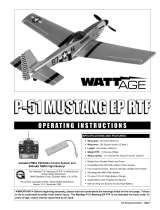
CONTENTS
1. Fuselage
2. Canopy Hatch
3. Spinner
4. Propeller
5. Propeller Adapter
6. Fixed Landing Gear w/ Covers
7. Horizontal Stabilizer
8. Foam Plugs
9. Tail Wheel
10. Wing
11. Cowl
1
4
7
2
5
8
3
6
9
10
11

5
BEFORE ASSEMBLY
❏
1. Read the Motor Safety Precautions section on page
13 of this manual. Charge the battery pack following the
instructions that came with your charger.
❏
2. Remove all of the components from the plastic packaging
and lay them out on your work surface. Set the wing aside
and begin the fuselage assembly.
ASSEMBLE THE FUSELAGE
❏
1. Remove the canopy hatch. This is held on by three
small magnets under the base of the canopy and a molded
tab at the front edge. To remove the hatch, pull up the rear
of the hatch.
❏
2. At the back of the fuselage you will see the opening
for the stabilizer. Look closely and you will see alignment
notches that help locate the stab position.
❏
3. On the bottom of the stabilizer you will nd the raised
alignment keys. These match up with the alignment notches.
❏
4. Slide the stabilizer into the opening in the fuselage.
When you install the stabilizer, slide the right side of the
stabilizer into the left side of the fuselage. Be sure to key the
stab to the slots in the fuselage. Position the stab so that it
is centered and the holes in the bottom of the fuselage are
aligned with the holes in the stabilizer.
❏
5. Partially install the two foam plugs into the holes in the
bottom of the fuselage. When you do this be sure the painted
end of the plug is outside of the fuselage. These two plugs
lock the stab to the fuselage. Once they are installed, the
tail cannot be removed without risk of breaking them, so be
sure you follow these instructions carefully. You will notice
that each of the plugs has an end that is angled. When the
plug is positioned properly the angle will be in line with the
bottom of the fuselage.
❏
6. When you are satis ed that you have the plugs positioned
properly, insert them into the fuselage and through the
stabilizer, locking the stabilizer in place.

6
❏
7. Remove the nylon Faslink from the end of the elevator
pushrod by rotating the Faslink until it unsnaps from the long
part of the pushrod and rotates around the L-bend. Install the
pushrod wire into the outermost hole in the elevator control
horn and secure it with the Faslink as shown.
RADIO SETUP
❏
1. Cut a 1” (25mm) piece of adhesive-backed hook and
loop material and stick the loop side (fuzzy side) to the
back of the receiver. Stick the hook side of the material just
behind the servo lead opening. Route the included aileron
Y-harness through the fuselage and plug it into the aileron
channel of the receiver or use separate channels for each
servo if preferred. Also, plug the rudder, elevator and ESC
into the receiver. Install the receiver in fuselage and tape
the receiver antennas in position as recommended by the
radio manufacturer.
❏
2. Separate the hook side from the loop side of the
remaining adhesive-backed hook and loop material. Stick
the hook side to the fuselage and the loop side to the back
of your battery pack. To prepare your other battery packs,
you may purchase more Great Planes hook and loop material
(GPMQ4480) from Tower Hobbies.
❏
3. Attach the wing to the fuselage with a 4mm x 50 mm
machine screw.
WARNING: Make sure the propeller is not installed. Always
switch on the transmitter rst with the throttle stick in the
low position before plugging in the LiPo battery. Always
unplug the LiPo battery before switching off the transmitter.
❏
4. Using your radio, center the elevator and rudder servos,
and trims on your transmitter. Make sure that the elevator
and rudder servo arms are 90° to the servo case when they
are centered. If they are not centered, remove the servo arm
retaining screw and reposition the arm on the splined shaft.
Reinstall the servo arm and the retaining screw.

7
❏
5. With the servos centered, check to make sure that the
control surfaces are centered. If they need to be adjusted,
loosen the locking screw on the pushrod connector and
adjust the ight control until it is centered. When you are
satis ed, tighten the locking screw to hold the pushrod wires
in position. For added security, we recommend removing the
locking screws, applying a drop of thread locking compound
to the threads and re-installing the locking screws.
❏
6. Using your radio, center the aileron servos. Check to see
that the ailerons are also centered. If they need adjustment,
loosen the locking screw and adjust the ailerons until they
are centered at zero de ection. Tighten the set screw of the
screw lock pushrod connector. Again, use threadlocker on
the threads.
OPTIONAL FLAP INSTALLATION
❏
1. Using a sharp hobby knife cut the end of the aps loose
from the wing.
❏
2. Cut a slot in the center of the ap control horn recess on
the bottom of the wing. Do not cut through the top of the ap.

8
❏
3. Use CA to glue the control horn in the slot with the quick
connector towards the wing root.
❏
4. Use a sharp hobby knife to cut the ap servo opening.
The foam over the opening is approximately ¼” (6mm) thick.
❏
5. To assist in pulling the ap servo leads through the
wing, tie a small nut (not included) to a string.
❏
6. Insert the nut in the opening in the ap servo recess.
Gently shake the wing to guide the nut and string to the
opening in the top center of the wing.
❏
7. Attach the ap servo lead to the string and carefully
pull it through the wing and out of the opening. Tip: Tie the
string to the retract cable and use a piece of masking tape
to position the string at the end of the connector.
❏
8. Connect a Y-harness to the ap servo lead.
❏
9. Plug the ap servo into the ap channel on the receiver.
Switch on the transmitter and then receiver. Check that the
servo arm is as shown with the ap control on the transmitter
set to aps up.

9
❏
10. Use CA, Canopy glue or thin double-sided tape (not
included) to secure the ap servo in the wing.
❏
11. Insert the z-bend of the ap pushrod in the outer hole
of the ap servo arm. Move the ap and insert the other
end of the ap pushrod in the quick connector on the ap
control horn.
❏
12. With the radio system on, set the ap control on the
transmitter to the ap up position. Position the ap so that
it is aligned with the trailing edge of the wing and tighten
the screw in the quick connector against the ap pushrod.
Repeat for the other ap servo and linkage.
❏
13. Operate the aps to make sure nothing binds and that
they both have the correct amount of throw.
INSTALL THE FIXED LANDING
GEAR (Optional)
This airplane is supplied with xed landing gear but this should
only be used if you have an asphalt or concrete runway. Any
length of grass will be too much resistance for the wheels to
roll on. Landing gear is not necessary for take off or landing.
The airplane is easily hand launched and lands very well on
its belly in grass.
❏
1. Install the main landing gear legs by tting them
into the slots in the bottom of the wing so that the wheel
faces inboard.
❏
2. Use the included hex wrench to remove the lower set
screw. Insert the tail gear wire, apply a drop of threadlocker
to the set screw and reinstall it, tightening it against the at
spot on the tail gear wire.
OPTIONAL RETRACT INSTALLATION
❏
1. To assist in pulling the retract lead wires through the
wing, tie a small nut (not included) to a string.

10
❏
2. Insert the nut in the opening in the retract recess. Gently
shake the wing to guide the nut and string to the opening in
the top center of the wing.
❏
3. Attach the retract lead to the string and carefully pull it
through the wing and out of the opening. Tip: Tie the string to
the retract cable and use a piece of masking tape to position
the string at the end of the connector.
❏
4. Remove the xed landing gear mount and attach the
retract with the four 2.5 x 8mm at head screws.
❏
5. Connect the two retract cables with a Y-harness and
plug it into the retract channel on the receiver. Check that
the retracts operate smoothly.
❏
6. Snap the optional retract landing gear covers onto the
landing gear wires.
GET THE MODEL READY TO FLY
Check the Controls & Control Direction
WARNING: Do not install the propeller!
❏
1. Turn on the transmitter, center the trims, and move the
throttle stick all the way down. Attach a charged battery.
❏
2. With the transmitter and receiver still on, check to make
sure that all of the control surfaces are correctly centered
so that they are at zero de ection. Check to see that the
locking screws on the pushrod connectors are tight and
that the servo arm locking screws are installed. Make sure
that the nylon Faslinks are also installed properly and are
holding the pushrods securely.
FULL THROTTLE
RUDDER
MOVES RIGHT
ELEVATOR MOVES DOWN
RIGHT AILERON MOVES UP
LEFT AILERON MOVES DOWN
❏
3. Make certain that the control surfaces and the throttle
respond in the correct direction as shown in the diagram.
If any of the controls respond in the wrong direction, use
the servo reversing in the transmitter to reverse the servos
connected to those controls. Be certain the control surfaces
have remained centered. Adjust if necessary. To arm the
motor, move the throttle stick to full, listen for the beeps,
then move it back to OFF. If the motor turns clockwise
when viewed from the front of the plane, remove the cowl
and switch any two wires going from the ESC to the motor.
Then, reinstall the cowl.

11
Check the Control Throws
The control throws are limited by the travel of the servos and
the mechanical set up of the pushrods. You can change the
control throw using the end-points or ATV feature of your
radio, or you can change the mechanical linkage to increase
or decrease the amount of control movement in relation to
the amount of servo movement. Keep in mind that changing
the throws mechanically is preferred to changing them using
your radio’s end-point adjustment. End points should be
used to “ ne-tune” to get the proper throws.
Hold a ruler up to the control surface while it is at zero throw
(neutral). Move the transmitter stick to the limit and measure
the amount of linear control throw. If your radio does not have
dual rates, we recommend setting the throws at the HIGH
rate setting. NOTE: The throws are measured at the widest
part of the elevators, rudder and ailerons.
If the control throws are too high, you can move the pushrod
connectors on the servo arms inward (toward the output
shaft) to decrease total travel.
These are the recommended control surface throws:
ELEVATOR
HIGH RATE LOW RATE
1/4"
[6 mm]
12 °
Up
1/4"
[6 mm]
12 °
Down
1/8"
[3mm]
6°
Up
1/8"
[3mm]
6°
Down
1/2"
[13 mm]
23°
Up
1/2"
[13 mm]
23°
Down
3/8"
[10 mm]
18°
Up
3/8"
[10 mm]
18°
Down
11/16"
[17 mm]
18°
Right
11/16"
[17 mm]
18°
Left
1/2"
[13 mm]
14°
Right
1/2"
[13 mm]
14°
Left
RUDDERAILERONS
1" [25 mm] 24°
DownOPTIONAL FLAPS
IMPORTANT! IMPORTANT! IMPORTANT!
Now that you have the throws set, be sure to set the
failsafe on the radio!
Install the Propeller & Spinner
IMPORTANT! Unplug the motor battery!
❏
1. Remove the prop nut and prop washer from the prop
adapter. Slide the prop adapter onto the motor shaft as shown.
❏
2. Fit the spinner backplate to the prop adapter. Fit the
propeller, prop washer, and prop nut. Position the propeller
so that the trailing edge of each blade touches the alignment
pin. Tighten the prop nut.
❏
3. Install the spinner using the two screws included in the
spinner parts bag.

12
Balance the Model (C.G.)
WARNING! DO NOT plug the motor battery into the ESC.
❏
1. At this stage the model should be in ready-to- y condition
with all of the systems in place including the motor, propeller,
spinner, radio system, battery and battery hatch. NOTE: The
landing gear will have a slight effect on the C.G. position.
❏
2. Use a felt-tip pen or 1/8" [3mm]-wide tape to accurately
mark the C.G. on the top of the wing on both sides of the
fuselage. The C.G. is located 3" [76mm] back from the
leading edge of the wing at the wing root where the wing
meets the fuselage.
This is where your model should balance for the rst ights.
Later, you may wish to experiment by shifting the C.G. up
to 1/4" [6mm] forward or 1/4" [6mm] back to change the
ying characteristics. Moving the C.G. forward may improve
the smoothness and stability, but the model may then
require more speed for takeoff and make it more dif cult
to slow for landing. Moving the C.G. aft makes the model
more maneuverable, but could also cause it to become too
dif cult to control. In any case, start at the recommended
balance point and do not at any time balance the model
outside the speci ed range.
❏
3. With all parts of the model installed (ready to y) and a
battery pack in place (do not connect it), place your ngers
on the marks you made and balance the model.
❏
4. If the tail drops, the model is “tail heavy” and the battery
pack must be shifted forward or weight must be added to
the nose to balance. If the nose drops, the model is “nose
heavy” and the battery pack must be shifted aft or weight
must be added to the tail to balance.
❏
5. Using a felt-tip pen, mark the position of the battery
pack in the battery compartment. This will help eliminate trim
changes or unwanted surprises each time that you change
the battery. When using different capacity batteries, you
may have to re-balance your plane and place an additional
mark in the battery compartment. If you plan to y the model
with and without landing gear, make separate marks to help
you know where to place the battery to balance correctly in
each con guration.
❏
6. If additional weight is required, use Great Planes
(GPMQ4485) “stick-on” lead. A good place to add stick-on
nose weight is to the motor box under the cowl (don’t attach
weight to the cowl—it is not intended to support weight).
Begin by placing increasing amounts of weight on the top
of the cowl over the rewall until the model balances. Once
you have determined the amount of weight required, it can
be permanently attached by removing the cowl and installing
the weight.
IMPORTANT: If you found it necessary to add any weight,
recheck the C.G. after the weight has been installed.
APPLY THE DECALS
❏
1. Be certain the model is clean and free from oily
ngerprints and dust. Prepare a dishpan or small bucket
with a mixture of liquid dish soap and warm water – about
½ teaspoon of soap per gallon of water. Submerse one of
the decals in the solution and peel off the paper backing.
Note: Even though the decals have a “sticky-back” and are
not the water transfer type, submersing them in soap and
water allows accurate positioning and reduces air bubbles
underneath.
❏
2. Position the decal on the model where desired. Holding the
decal down, use a paper towel to wipe most of the water away.
❏
3. Use a piece of soft balsa or something similar to
squeegee the remaining water from under the decal. Apply
the rest of the decals the same way.

13
PREFLIGHT
Identify Your Model
No matter if you y at an AMA sanctioned R/C club site or
if you y somewhere on your own, you should always have
your name, address, telephone number, AMA number and
FAA number on or inside your model. It is required at all AMA
R/C club ying sites and AMA sanctioned ying events and
simply a “good idea” even if ying somewhere else. Fill out the
identi cation tag on page 15 and place it on or in your model.
Charge the Battery
Be certain to refer to the instructions that accompany the
charger to properly and safely charge the battery that goes
in the model and powers the motor and controls.
When discharging the battery, DO NOT attempt to fully
discharge the battery pack by repeatedly running the motor
to the ESC’s low voltage cutoff. This will drastically shorten
the life of your Lithium polymer (LiPo) batteries and could
cause the individual cells to become imbalanced.
MOTOR SAFETY PRECAUTIONS
● WARNING: Once the motor batteries are connected
the electric motor can start at any time. Make sure the
fail safe is set on your radio to prevent the motor from
starting if the signal is lost.
● WARNING: Read the entire instruction sheet included
with your motor batteries. Failure to follow the instructions
could cause permanent damage to the battery and its
surroundings and cause bodily harm!
● WARNING: Get help from an experienced pilot when
learning to operate electric motors.
● ALWAYS keep these items away from the prop: loose
clothing, shirt sleeves, ties, scarfs, long hair or loose
objects such as pencils or screwdrivers that may fall
out of shirt or jacket pockets into the prop.
● ALWAYS keep your face and body as well as all
spectators away from the plane of rotation of the
propeller as you start and run the engine.
● ALWAYS wear safety glasses when operating the motor.
● ALWAYS remove the propeller if the motor batteries will
be connected when working on your plane.
● ALWAYS remove the motor batteries when charging.
● ALWAYS follow the charging instructions included with
your charger for charging LiPo batteries. LiPo batteries
can cause serious damage if misused.
● ALWAYS unplug the motor batteries rst.
● ALWAYS use a LiPo approved charger.
● ALWAYS set the charger’s output volts to match the
battery volts.
● ALWAYS charge a LiPo battery in a reproof location.
● ALWAYS charge through the “charge” lead.
● ALWAYS KEEP OUT OF THE REACH OF CHILDREN.
● ALWAYS remove the batteries from the plane after a
crash. Set them aside in a safe location for at least 20
minutes. If the batteries are damaged in the crash they
could catch re. If the battery starts to swell, quickly
move the battery to a safe location, preferably outside.
Place it in a bucket, covering the battery with sand.
Never use water to try and put out a LiPo re.
● NEVER operate the motor in an area of loose gravel
or sand; the propeller may throw such material in your
face or eyes.
● NEVER touch the motor during or right after operation.
The motor gets HOT!
● NEVER switch off the transmitter with the motor
batteries plugged in.
● NEVER use a NiCd/NiMH peak charger to charge a
LiPo battery.
● NEVER charge in excess of 4.20v per cell unless the
battery is rated for a higher voltage.
● NEVER charge through the “discharge” lead.
● NEVER charge at currents greater than 1C unless the
battery is rated for a higher charge rate.
● NEVER trickle charge a LiPo battery.
● NEVER allow the battery temperature to exceed 150
degrees F (65° C).
● NEVER disassemble or modify the pack wiring in any
way or puncture the cells.
● NEVER discharge below 2.7V per cell.
● NEVER place the battery or charger on combustible
materials or leave it unattended during charge or
discharge.
● NEVER charge the batteries in the plane.
FLYING THE P-51 MUSTANG
While the P-51 is fairly easy to y, it is not a trainer. If you have
never own a model aircraft before, it is strongly suggested
that you learn to y with the assistance of an experienced
R/C pilot.
Find a Suitable Flying Site
Find a ying site clear of buildings, trees, power lines and other
obstructions. Until you know how much area will be required
and have mastered ying your P-51, a site at least the size
of two or three football elds should be adequate—a ying
eld speci cally intended for R/C planes is best. Don’t y
within six miles of R/C ying elds and never y near people.

14
Perform a Range Check
As a precaution, an operational ground range test should be
performed before the rst ight each time out. Performing a
range test is a good way to detect problems that could cause
loss of control such as low batteries, defective or damaged
radio components or radio interference. This usually requires
an assistant and should be done at the actual ying site you
will be using.
First, put the throttle stick in the low position and turn on the
transmitter. Then, install the fully charged battery into the
fuselage. Connect the battery and install the hatch.
Remember, use care not to “bump” the throttle stick.
Otherwise, the propeller will turn, possibly causing damage
or injury.
Begin walking away from the model operating the controls in
a predictable pattern (for example: Up, then down elevator.
Right, then left aileron. Right, then left rudder). While moving
the control surfaces, also vary motor rpm. Have your assistant
alert you if the controls fail to respond or if they move suddenly
or erratically. You should be able to maintain control up to a
distance of approximately 100' [30m].
If the controls respond erratically or if anything else seems
wrong, make certain all the servo wires are securely connected
to the receiver and that the transmitter batteries are fully
charged. If you cannot nd a mechanical problem with the
model, it is slightly possible that there is radio interference
somewhere in the area. One option would be to try another
range check at an alternate ying site.
Monitor Your Flight Time
Monitor and limit your ight time using a timer such as the one
on your wrist watch. When the batteries are getting low you
will usually notice a performance drop before the ESC cuts
off motor power, so when you notice the plane ying slower
you should land. Often (but not always!), power can be brie y
restored after the motor cuts off by holding the throttle stick
all the way down for a few seconds, then moving it up again.
To avoid an unexpected dead-stick landing on your rst ight,
set your timer to a conservative 5 minutes. When the alarm
sounds you should land your model.
When you learn how much ight time you are getting you
can adjust your timer accordingly. Always be conservative so
the motor won’t quit unexpectedly and you will have enough
battery to land under power. We recommend that you do
not use more than 80% of the battery capacity to ensure a
longer battery life.
Take Off
Until you have become comfortable with ying your P-51,
do not y if the wind speed is greater than 10 mph [16
kilomoters/hr].
One nal check before takeoff: always double-check the
ight control response to your inputs from the transmitter
before every ight. Be certain the ailerons, elevator and
rudder respond correctly and that none of the controls has
inadvertently become reversed.
If the surface is smooth (such as pavement or blacktop)
the P-51 can take off from the ground. But most grass is
probably too tall, so if ying from grass the model will have
to be hand launched.
ROG Take Off
If taking off from the ground, place the model on your “runway”
with the nose pointing directly into the wind—this will reduce
the ground speed that must be reached and automatically
provide “heading assist” making steering and takeoff easier.
Slowly advance the throttle, adding rudder correction as
needed to keep the model rolling straight. When the plane
becomes “light” continue to apply throttle until you are at
full-power—all this will happen in a few seconds. When
suf cient liftoff speed has been reached, gradually apply
“up” elevator allowing the model to leave the ground. Do not
“yank” up on the stick—rather, be smooth and allow the plane
to establish a gentle climb.
Once you have reached a safe ying speed at a comfortable
altitude (approximately 50' [15m]), work the controls as
necessary to establish a gentle turn away from the runway,
and bring the optional retractable landing gear up.
Flying
One thing to remember is that, when the plane is ying away
from you, moving the aileron stick to the right will make
the plane bank to your right. However, when the model is
ying toward you, moving the aileron stick to the right will
make the plane move to your left. Of course, the plane is
still responding the same way, it’s just that your orientation
has reversed. This must be kept in mind while learning to
y (and is also a good reason to take ight lessons from an
experienced pilot!).
To establish a turn, “up” elevator (pulling back on the stick)
is usually required along with aileron input to get the model
into a bank. To stop the turn, apply a small amount of
opposite aileron.
Once you get the plane into the air and have climbed to a
comfortable altitude, the rst “order of business” will be to
“trim” the model for straight-and-level ight. The model ies
best at approximately 3/4-throttle. Adjust the trims on the
transmitter to make minor control surface adjustments as
necessary until the plane will y straight without any control
inputs. Often, your assistant can reach over and adjust the
trims for you.

15
Remember to keep the model high enough to give yourself
time to make corrections, but don’t let it get too far away.
Otherwise, it will be dif cult to detect its attitude and which
way it is going.
One nal check before landing: see how the model will react
when it’s time to land and you reduce the throttle. To do this,
while still at altitude, cut the motor power. The model should
establish a gentle, downward glide path. This is how the
model will react when it’s actually time to land. Add power
and climb back up to your original altitude.
Practice a few of these “climb and glides” to judge how far
out you will need to be when it’s time to land.
If optional aps have been installed, slow the plane and lower
the aps. Check to see if it climbs with aps. If it does, a
small amount of down elevator can be mixed in.
Landing
To land, y down-wind past the landing area. Gently turn
into the wind, and reduce the throttle so that the airplane
initiates a descending glide path. If optional aps have been
installed, lower them now. If necessary, add power to extend
the glide path to reach the runway. As the model approaches
and loses altitude, gradually and proportionally add “up”
elevator to control the glide path and altitude. Continue to
apply elevator until the model touches down at which time
you should be holding full, or nearly full, up elevator. This will
cause the airplane to slow and settle to the ground.
CAUTION: If, during a rough landing, the propeller be-
comes jammed and cannot rotate, the battery and speed
control will become very hot if you attempt to add power.
Immediately move the throttle down to stop the motor. If
you fail to do this, the motor, speed control and/or battery
will be damaged.
AFTER EACH FLIGHT
Disconnect the battery and remove it from the airplane. Then,
turn off the transmitter. Allow the battery to cool before
recharging, or allow the motor to cool before installing another
battery for the next ight. Inspect the airplane to make sure
nothing has become loose or damaged.
REPAIRING YOUR MODEL
If your model becomes damaged, it can be repaired using
regular medium CA. Spare parts are available – please see
the parts list earlier in this manual for more details of what is
available and how to get new parts. CA debonder (GPMR6039)
is available if you ever need to dissolve the CA adhesive you
used to build or repair this model.
Have a ball! But always stay in control
and y in a safe manner.
GOOD LUCK AND GREAT FLYING!
This model belongs to:
Name
Address
City, State, Zip
Phone Number
FAA Number
AMA Number

16
© 2016 Tower Hob bies .
®
A subsidiary of Hobbico, Inc.
v1.1
/