Page is loading ...

CENTRALE DI COMANDO PER
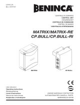
CONTROL UNIT FOR
STEUEREINHEIT FÜR
CENTRALE DE COMMANDE POUR
CENTRAL DE CONTROL PARA
CENTRALKA STEROWANIA DLA
L8542331
Rev. 04/04/04
MS4
Libro istruzioni
Operating instructions
Betriebsanleitung
Livret d’instructions
Libro de instrucciones
Książeczka z instrukcjami
UNIONE NAZIONALE COSTRUTTORI
AUTOMATISMI PER CANCELLI, PORTE,
SERRANDE ED AFFINI

2
3
3
Dichiarazione CE di conformità Déclaration CE de conformité
EC declaration of conrmity Declaracion CE de conformidad
EG-Konformitatserklarung Deklaracja UE o zgodności
Con la presente dichiariamo che il nostro prodotto
We hereby declare that our product
Hiermit erklaren wir, dass unser Produkt
Nous déclarons par la présente que notre produit
Por la presente declaramos que nuestro producto
Niniejszym oświadczamy że nasz produkt
MS4
è conforme alle seguenti disposizioni pertinenti:
complies with the following relevant provisions:
folgenden einschlagigen Bestimmungen entspricht:
correspond aux dispositions pertinentes suivantes:
satisface las disposiciones pertinentes siguientes:
zgodny jest z poniżej wyszczególnionymi rozporządzeniami:
Direttiva sulla compatibilità elettromagnetica (89/336/
CCE, 93/68/CEE)
EMC guidelines (89/336/EEC, 93/68/EEC)
EMV-Richtlinie (89/336/EWG, 93/68/EWG)
Directive EMV (89/336/CCE, 93/68/CEE) (Compatibilité
électromagnétique)
Reglamento de compatibilidad electromagnética (89/336/
MCE, 93/68/MCE)
Wytyczna odnośnie zdolności współdziałania elektromagne-
tycznego (89/336/EWG, 93/68/EWG)
Norme armonizzate applicate in particolare:
Applied harmonized standards, in particular:
Angewendete harmonisierte Normen, insbesondere:
Normes harmonisée utilisées, notamment:
Normas armonizadas utilzadas particularmente:
Normy standard najczęściej stosowane:
EN 55022, EN 61000-3-2, EN 61000-3-3, EN 50082-1
Data/Firma
Direttiva sulla bassa tensione (73/23/CEE, 93/68/CEE)
Low voltage guidelines (73/23/EEC, 93/68/EEC)
Tiefe Spannung Richtlinie (73/23/EWG, 93/68/EWG)
Directive bas voltage (73/23/CEE, 93/68/CEE)
Reglamento de bajo Voltaje (73/23/MCE, 93/68/MCE)
Wytyczna odnośnie niskiego napięcia (73/23/EWG, 93/
68/EWG)
Norme armonizzate applicate in particolare:
Applied harmonized standards, in particular:
Angewendete harmonisierte Normen, insbesondere:
Normes harmonisée utilisées, notamment:
Normas armonizadas utilzadas particularmente:
Normy standard najczęściej stosowane:
EN 60204-1, EN 60335-1
Data/Firma
Automatismi Benincà Srl
Via Capitello, 45
36066 Sandrigo (VI)
ITALIA

6
7
Control unit for MS4
The electronic control unit MS4 can be used to control motors with power not exceeding 500W.
GENERAL WARNINGS
a) The wire connections and the operating logic should be in compliance with regulations in force.
b) The cables featuring different voltage should be physically detached, or adequately insulated by an
additional insulation of at least 1 mm.
c) The cables should be further fastened in proximity to the terminals.
d) Check all connections before powering the unit.
e) Check that setting of the Dip-Switches are the required ones.
f) Normally Closed inputs which are not in use should be short-circuited by means of Dip SW4, see wire
diagram
g) When the unit is powered, the LED ”PGM” should ash; conversely, check the good condition of fuses
and that power supply is 230V AC, 50Hz between terminals 1 and 2 (INPUT 230VAC – keep to phase/
neutral).
INPUT/OUTPUT FUNCTIONS
Term. No. Function Note
1-2 Power supply Input, 230VAC 50Hz (1-Phase/2-Neutral)
3-4 Primary Transf. Connection of winding of primary transformer, 230V AC
5-6 Flashing light Output, connection of ashing light, 230VAC 40W max.
7-8 24 V AC Output, power supply of accessories, 24VAC/0.4A max.
9-10 SCA Connection of open gate indicator light, 24 VAC/3W max.
11 +V Common to all control inputs.
12 CHIUDE Input, Close push-button (N.O. contact)
13 APRE Input, Open push-button (N.O. contact)
14 P.P. Input, Step-by-step push-button (N.O. contact)
15 STOP Input, STOP push-button (N.C. contact)
16 FTC Input, connection of safety devices, N.C. contact (eg. photocells)
17 FCA Input, Open limit switch (N.C. contact)
18 FCC Input, Close limit switch (N.C. contact)
19-20 DAS Connection of safety edge. Input with calibrated resistance or with
N.C. contact:
If a resistive safety edge is in use, jumper J4 is to be closed.
If a mechanical safety edge is in use, jumper J4 is to be opened.
If an obstacle hits the edge, the control unit stops the gate and the
movement is reversed for about 2s.
If the edge is not in use, open jumper J4 and short-circuit terminals
19-20. Do not connect the edge to the common terminal.
21-22 RX 2ch. Output, second radio channel of the receiver.
N.O. contact, voltage-free.
23-24 Aerial Connection to aerial, radio-receiver card.
(23-screen/24-signal).
25-26 Secondary Transf. Connection, winding of secondary transformer, 24VAC
27-28 Capacitor Connection, capacitor
29-30-31 Motor Connection, motor : (29-move/30-move/31-Com)
To check connections:
1) Cut-off power supply.
2) Manually release the wing, move it to approx. half-stroke and lock it again.
3) Reset power supply.
4) Send a step-by-step control signal by pressing the button or the remote control key.
5) The wing should start an opening movement. If this is not the case, invert the movement wires (29< >30)
of the motor and the limit switch wires FCA-FCC (17< >18).
6) Adjust Time, Operating Logic and Motor Power.

8
9
Adjustment of the motor power
WARNING! This adjustment affects the safety of the automatic system.
Check that the thrust applied onto the wing complies with regulations in force.
The motor torque can be adjusted only when the gate is still. The power levels are 6.
- Press the POT push-button for 1s and release it.
- At each pressing of the POT push-button , power is increased. This increase is shown by the indicator bar
LED “POWER”.
- Once the maximum power is reached, if the push-button is pressed again, the sequence restarts from the
minimum power value.
- Store the desired value in memory by keeping the POT button pressed for 5s, the D1 green LED stays on
during the 5s. At end of storage, this LED switches off.
Functions of Trimmers
TCA It allows the adjustment of the automatic closure time. Check Dip-Switch N°2= ON.
This function can be adjusted between 1 s minimum and 250 s maximum.
TL It allows the maximum time of the opening and closing phases.
This function can be adjusted between 5 s minimum and 70 s maximum.
Braking :
During the last 14 seconds of the preset operating time, the control unit carries out a braking
operation by reducing the motor speed.
It is recommended to preset the TL operating time 7 seconds longer than the stroke time in order
to allow a 7-second braking.
If the braking function is not required, increase the TL for a time longer that 14 seconds with
respect to the stroke time.
Dip-Switch functions SW2 “SELECT”
DIP 1 The operating mode of ”Pulsante P.P.” (Step-by-step push button) and of the transmitter is
selected.
Off: operation: Open > Stop > Close > Stop
On: operation : Open > Stop > Close > Stop
DIP 2 The automatic closure is enabled or disabled.
Off: disabled automatic closure
On: enabled automatic closure
DIP 3 The multi-at function is enabled or disabled.
Off: disabled multi-at function.
On: enabled multi-at function. The P.P. (Step-by-step) impulse or the impulse of the transmitter
have no effect in the opening phase.
DIP 4 Forewarning ashing light enabled or disabled
Off: disabled forewarning ashing light.
On: enabled forewarning ashing light. The ashing light is activated 3 s before the starting of the
motor.
DIP 5 Motor start pickup
Off: disabled pickup.
On: enabled pickup. The maximum torque of the motor is for approx. 1 sec. from start.
DIP 6 Activation of FTC input in the opening phase.
Off: No activation. In the opening phase, the FTC input (photocells) is disabled.
On: Temporary stop. In the opening phase, the FTC input (photocells) is enabled.
If an obstacle is detected, the wing movement stops, until the photocells are deactivated.
DIP 7 Function of APRE (OPEN) input
Off: This input works as “OPEN” control
On: This input works as “PEDESTRIAN” control. It provides an opening movement of 15s.
DIP 8 The electronic brake is enabled or disabled
Off: Electronic brake disabled.
On: Electronic brake enabled. For heavier gates, this function is to be enabled in order to
compensate the gate wing inertia in case the gate stops or reverses its movement.

8
9
Dip-Switch SW4 “BYPASS” functions
The “Bypass” dip-switches permit the normally inputs which are not in use to be short circuited (excluding
DAS input)
DIP 1 STOP Input
Off: enabled input
On: disabled input
DIP 2 FTC Input
Off: enabled input
On: disabled input
DIP 3 FCA Input
Off: enabled input
On: disabled input
DIP 4 FCC Input
Off: enabled input
On: disabled input
NOTE: All adjustment of Trimmers and Dip-Switches should be carried out with motor stopped.
To check the good conditions of the power circuit
The control unit provides testing of the power circuit good conditions (TRIAC).
The unit comes factory-adjusted with this function disabled.
This test function can be enabled or disabled as follows:
To enable the test function to check the power circuit good conditions:
1 Move the DIP 8 to OFF
2 Cut-off mains power supply
3 Reset the mains power supply by pressing the PGM button for 2 seconds.
4 With control activated, should a failure in the power circuit occur or in case of faulty thermal switch in the
motor, all LEDs of the “Power” stirp will start ashing. The control unit will execute no control.
To disable the test function to check the power circuit good conditions:
1 Move the DIP 8 to ON
2 Cut-off mains power supply
3 Reset the mains power supply by pressing the PGM button for 2 seconds.
4 With the deactivated function, even in the case of faulty power circuit, the control unit will execute the
controls.
To check whether the test function is deactivated, cut-off power to the control unit. When the power supply
is reset, the LED D1 ashes fast and then normally, to indicate that the function is deactivated.
LED diagnostic
The control unit is complete with a series of self-diagnosis LEDs which allow to check all functions:
LED DAS Switches off when Input DAS is activated
LED FCC Switches off when the Closure Limit Switch is activated
LED FCA Switches off when the Opening Limit Switch is activated
LED FTC Switches off when the photocells are not aligned or when an obstacle is detected
LED STOP Switches off when Input STOP is activated
LED P.P. Switches on when Input Step-by-Step is activated
LED OPEN Switches on when Input OPEN is activated
LED CLOSE Switches on when Input CLOSE is activated
LED D1 Flashes to indicate mains power supply and the correct to operation of the
microprocessor.
/