Page is loading ...

L8542337
Rev. 11/03/03
SA02M
CENTRALINA A MICROPROCESSORE
CONTROL UNIT WITH MICROCONTROLLER
MIKROCONTROLLER-STEUERUNG
CENTRALE A MICROCONTRÔLEUR
CENTRALITA A MICROPROCESADOR
CENTRALKA Z MIKROPROCESOREM
Libro istruzioni
Operating instructions
Betriebsanleitung
Livret d’instructions
Libro de instrucciones
Książeczka z instrukcjami
UNIONE NAZIONALE COSTRUTTORI
AUTOMATISMI PER CANCELLI, PORTE,
SERRANDE ED AFFINI

2
Dichiarazione CE di conformità Déclaration CE de conformité
EC declaration of confirmity Declaracion CE de conformidad
EG-Konformitatserklarung Deklaracja UE o zgodności
Con la presente dichiariamo che il nostro prodotto
We hereby declare that our product
Hiermit erklaren wir, dass unser Produkt
Nous déclarons par la présente que notre produit
Por la presente declaramos que nuestro producto
Niniejszym oświadczamy że nasz produkt
SA02M
è conforme alle seguenti disposizioni pertinenti:
complies with the following relevant provisions:
folgenden einschlagigen Bestimmungen entspricht:
correspond aux dispositions pertinentes suivantes:
satisface las disposiciones pertinentes siguientes:
zgodny jest z poniżej wyszczególnionymi rozporządzeniami:
Direttiva sulla compatibilità elettromagnetica (89/336/
CCE, 93/68/CEE)
EMC guidelines (89/336/EEC, 93/68/EEC)
EMV-Richtlinie (89/336/EWG, 93/68/EWG)
Directive EMV (89/336/CCE, 93/68/CEE) (Compatibilité
électromagnétique)
Reglamento de compatibilidad electromagnética (89/336/
MCE, 93/68/MCE)
Wytyczna odnośnie zdolności współdziałania elektromagne-
tycznego (89/336/EWG, 93/68/EWG)
Norme armonizzate applicate in particolare:
Applied harmonized standards, in particular:
Angewendete harmonisierte Normen, insbesondere:
Normes harmonisée utilisées, notamment:
Normas armonizadas utilzadas particularmente:
Normy standard najczęściej stosowane:
EN 55022, EN 61000-3-2, EN 61000-3-3, EN 50082-1
Data/Firma
Direttiva sulla bassa tensione (73/23/CEE, 93/68/CEE)
Low voltage guidelines (73/23/EEC, 93/68/EEC)
Tiefe Spannung Richtlinie (73/23/EWG, 93/68/EWG)
Directive bas voltage (73/23/CEE, 93/68/CEE)
Reglamento de bajo Voltaje (73/23/MCE, 93/68/MCE)
Wytyczna odnośnie niskiego napięcia (73/23/EWG, 93/
68/EWG)
Norme armonizzate applicate in particolare:
Applied harmonized standards, in particular:
Angewendete harmonisierte Normen, insbesondere:
Normes harmonisée utilisées, notamment:
Normas armonizadas utilzadas particularmente:
Normy standard najczęściej stosowane:
EN 60204-1, EN 60335-1
Data/Firma
Automatismi Benincà Srl
Via Capitello, 45
36066 Sandrigo (VI)
ITALIA

3
C10
C9
C7
R2
RTX1
C11
R6
Q2
Q1
R28
R8
R3
R8
R26
C5
C4
R1
Z4
D1
D2
D3
U3
Z6
R31
U4
R32 C8
F2 2A
1-PP Mod.
2-C.A.
3-Cond.
4-Prelamp.
R19
R30
R15
D4
Z5
R27
R17
R14
C12
Z1
C13
Z2
C14
Z3
C16
R11
R9
R23
R12
R24R25
Q3
SA02M
V1.0
D5
U2
R5
R16
R29
R18
C15
R13R10
U1
R20
R21
R22
18 19 20 21 22 23 25 26
FUSE
FUSE
M2
Lamp
F
F1
1 2
3 4 5 6 7 8 9 10 11
12 13 14 15 16 17
Ant. Gnd
SCA P.P. Stop FTC
TL TCA
PGM
TRAC
+V 24VAC ELS
24V 12V 0V Power NT FT F1 6.3A
F2 K3 K5
C1C3C2
K4K1K2
N M1
COM
Ingresso pulsante pedonale
Input, pedestrian entrance push-button
Eingang, Fußgängereingang Taste
Entrée bouton entrée piétonne
Entrada pulsador entrada de peatones
Wejście dla przycisku nożnego

6
SA02M Control unit with microcontroller
The SA02M control unit with microcontroller can be used with motors having a power not exceeding 750W.
Attention: Whenever the power supply is restored and a Step-by-Step command is given to the control unit,
you must wait until the automation has completed the whole interval defined by the work time (wait until the
blinker switches off).
Installation instructions.
a) The electrical installation and functioning logic must comply with current standards.
b) Keep the power cables (for the motor and power supply) away from the control cables (buttons, photocells,
radio). To avoid interference use two separate sheaths (see EN 60204-1 15.1.3).
c) Check all the connections again before supplying voltage.
d) Check that the Dip-Switch settings are as required.
e) The Normally Closed contacts which are not in use should be short circuited.
f) If the direction of the motor rotation is not correct, invert the ”OPEN” - ”CLOSE” wires of the motor.
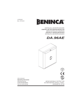
Input/Output functions
(1) Antenna Signal
(2) Antenna Shield
(3,8) SCA= Indicator lamp, Open gate
(4) P.P.= Input, Step-by-Step push-button (N.O. contact).
(5) Stop= Input, Stop push-button (N.C. contact).
(6) FTC= Input, photocell receiver (N.C. contact).
(7) +V= Common, all control inputs.
(8,9) OUT24VAC= Output, 24Vac auxiliary power supply (100mA max.).
(10,11) ELS.= Connection to 12V Electric lock
(12,13,14) To secondary of the Capacitor
(15,16,17) To primary of the Capacitor
(18,19) INPUT 230VAC= Control unit power supply, 230Vac, 50Hz (keep to phase/neutral).
(20,21) Lamp= Flashing light
(22,23,24) APRE/CHIUDE/COM= To relevant terminals of Motor 2, at 230Vac, 50Hz.
It is mandatory to connect the Ground wire (yellow/green) on the motor frame.
(24,25,26) COM/APRE/CHIUDE= To relevant terminals of Motor 1 at 230Vac, 50Hz.
It is mandatory to connect the Ground wire (yellow/green) on the motor frame.
If the control for the pedestrian entrance is to be used, connect the normally open (N.O.) button between the +V
input (common of controls) and the pin between P.P. and STOP.
The control unit is equipped with a built-in radio module for the reception of both fixed code and variable code
remote controls at a frequency of 433.92MHz.
To use a remote control its data should be stored in the unit memory. This procedure is shown hereunder. The
unit is able to memorize up to 14 different codes.
Dip-switch functions
DSW1 The operation of the “Step-by-Step button” and the remote control can be selected with this Dip-
Switch.
Off= ”OPEN” - ”STOP” - ”CLOSE” functioning
On= ”OPEN” - ”CLOSE” - ”OPEN” functioning.
DSW2 This enables or disables the automatic closure.
Off= Automatic closure disabled
On= Automatic closure enabled
DSW3 It enables or disables the multi-flat function.
Off= Multi-flat function disabled
On= Multi-flat function enabled
DSW4 It enables or disables the forewarning flashing light.
Off= Forewarning flashing disabled
On= Forewarning flashing enabled
Trimmer functions
TCA This allows the automatic closure time to be adjusted when this is enabled by positioning the DSW2
Dip-switch on ON.
Adjustment can be from a minimum of 1 to a maximum of 250 seconds.
The minimum time is obtained by rotating the trimmer completely anticlockwise.
TL This allows the working time of the automation to be adjusted. If the limit switches fail, the software

7
protection will intervene after this time has elapsed. (Add about 4 sec. to the actual stroke time of the
automation). Adjustment can be from a minimum of 1 to a maximum of 125 seconds.
The minimum time is obtained by rotating the trimmer completely anticlockwise.
Note: TL is read by the control unit only at end of operation. Hence, if the Trimmer position is changed
to modify the following operation it is necessary to wait for the TL of the previuous movement to elapse,
otherwise cut power off the unit to reset.
TRAC This allows to regulate the delay time after which the second gate leaf starts its closing movement. The
adjustment ranges from 1 sec. min. to 40 sec. max
The minimum time is obtained by turning the trimmer completely anticlockwise.
Programming of the control unit
To erase the remote control codes from memory
To erase the codes from the memory, power the control unit by keeping the PGM programming push-button
pressed. The flashing light switches on. When the flashing light switches off, the memory is erased.
To store a new remote control code in memory
Press the PGM programming button, SCA will start to flash fast until a new remote control is received and stored
in memory. If, after pressing the button, SCA is not flashing but the flashing light for 5S switches on, this means
that memory is full and no more codes can be stored in.
Adjustment of the motor power
A faston connector is provided on the power transformer which allows to adjust the power of motors on 4 dif-
ferent levels. The minimum power is obtained by moving the Faston to120, by moving the Faston to 230 the
power will be maximum.
/