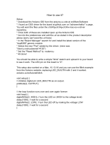
// initial period of the blink is 1 second
byte dimmerValue = 100; // in 10 ms
// add one Switch Multilevel channel
ZUNO_SETUP_CHANNELS(ZUNO_SWITCH_MULTILEVEL(getter, setter));
// this function runs once, when you press reset
// or power the board
void setup() {
// set digital pin 13 (built-in LED) as an output.
pinMode(LED_BUILTIN, OUTPUT);
}
// this function loops consecutively forever
void loop() {
digitalWrite(LED_BUILTIN, HIGH); // turn the LED on
delay(dimmerValue * 10); // wait for timeout
digitalWrite(LED_BUILTIN, LOW); // turn the LED off
delay(dimmerValue * 10); // wait for timeout
}
// callback function that runs
// when a new value comes from Z-Wave Network
// this is a setter referenced in channel creation
void setter(byte newValue) {
// save new value in a variable
dimmerValue = newValue;
}
// callback function that runs when asked for the
// current blink rate from Z-Wave Network
// this is a getter referenced in channel creation
byte getter(void) {
// return previously saved value
return dim m erValue;
}
FCC statementBlink Sample Code
Z-Uno FCC ID: 2ALIB-ZMEZUNO2
This device complies with Part 15 of the FCC Rules. Operation is subject to the following two
conditions:
(1) This device may not cause harmful interference, and
(2) This device must accept any interference received, including interference that may cause
undesired operation.
NOTE: This equipment has been tested and found to comply with the limits for Class B digital
devices, pursuant to Part 15 of the FCC rules. These limits are designed to provide reasonable
protection against harmful interference in a residential installation. This equipment generates,
uses and can radiate radio frequency energy and, if not installed and used in accordance with
the instructions, may cause harmful interference to radio communications. However, there is
no guarantee that interference will not occur in aparticular installation. If this equipment does
cause harmful interference to radio or television reception, which can be determined by turning
the equipment off and on, the user is encouraged to try to correct the interference by one or
more of the following measures:
1. Reorient or relocate the receiving antenna.
2. Increase the distance between the equipment and the receiver.
3. Connect the equipment into an outlet on a different circuit to which the receiver isconnected.
4. Consult the dealer or an experienced radio/TV technician for assistance.
Use of the shielded cable is required to comply with Class B limits in Subpart B of Part 15 of the
FCC rules.
Do not make any changes or modications to the equipment unless otherwise specied in
the manual. If such changes ormodications should be made, it may be necessary to stop the
operation of the equipment.
NOTE: If static electricity or electromagnetism causes data transfer to discontinue midway (fail),
restart theapplication or disconnect and connect the communication cable (USB, etc.) again.
Radiation Exposure Statement: This equipment complies with the set out FCC radiation
exposure limits for anuncontrolled environment.
Co-location warning: This transmitter must not be co-located or operated in conjunction with
any other antenna or transmitter.
OEM integration instructions: This module has a LIMITED MODULAR APPROVAL, and is intended
only for OEM integrators under the following conditions: As a single, non-colocated transmitter,
this module has no restrictions in relation to a safe distance from any user. The module shall be
only used with the antenna(s) that has/have been originally tested and certied with this module.
Aslong as these conditions above are met, further transmitter testing will not be required.
However, the OEM integrator is still responsible for testing their end-product for any additional
compliance requirements necessary for this installed module (for example, digital device
emissions, PC peripheral requirements, etc.).


