Instruction sheet for BA201
Communications Isolator
1. INTRODUCTION
These instructions describe the function, certification, installation, safe
use and maintenance of the BEKA BA201 Communications Isolator.
This isolator is primarily intended for communicating with and powering
BEKA intrinsically safe Serial Text Displays, but may be used with other
intrinsically safe hazardous area equipment having compatible intrinsic
safety parameters.
2. DESCRIPTION
The BA201 Communications Isolator is a dedicated interface for
connecting intrinsically safe BEKA Serial Text Displays, such as the
BA484D and the BA488C, to a safe area computer system. It is
certified as intrinsically safe associated apparatus and must be installed
in a non-hazardous safe area. The BA201 provides intrinsically safe
galvanic isolation between the safe and hazardous areas, plus
conversion of RS232 or RS485 serial data to the dedicated 2 or 3-wire
communications signalling required by BEKA Serial Text Displays.
The BA201 Communications Isolator also powers the Serial Text
Display and, depending upon the wiring configuration, up to four
displays may be connected to each BA201 Isolator. To prevent earth
loops, both communications ports are functionally isolated from the
BA201 power supply allowing an earthed or floating supply to be used.
3. CERTIFICATION
The BA201 Communications Isolator has the following intrinsic safety
associated apparatus certifications that permit installation throughout
the world:
IECEx IECEx ITS 07.0014
ATEX ITS07ATEX25602
UKCA ITS21UKEX0086
FM Entity & Nonincendive
File number 3029711
cFM Entity & Nonincendive
File number 3029711C
The IECEx, ATEX and UKCA certifications and installations, which
comply with similar standards, are described in the main section of this
instruction sheet.
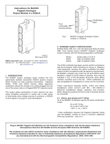
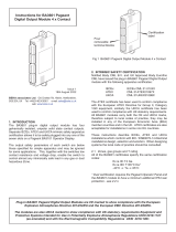
Fig 1 BA201 dimensions and terminal numbers
3.1 IECEx, ATEX and UKCA certification
UK Approved Body Intertek Testing & Certification Ltd have issued the
BA201 Communication Isolator with an IECEx Certificate of Conformity
IECEx ITS 07.0014. They have also issued a UK-Type Examination
Certificate ITS21UKEX0086 which has been used to claim compliance
with UK statutory requirements for II (1) G [Ex ia Ga] IIC associated
apparatus.
Notified Body Intertek Italia S.p.A. have issued the BA201
Communication Isolator with EU-Type Examination Certificate
ITS07ATEX25602. which has been used to claim compliance with the
European ATEX Directive 2014/30/EU for II (1) G [Ex ia Ga] IIC
associated apparatus.
The Communications Isolator carries the Community and UKCA Marks,
subject to local codes of practice, it may be installed in any of the EEA
member countries and in the UK. The IECEx certificate allows
worldwide installation, either directly or as a means to obtain local
approval. This instruction sheet describes installations which conform
to EN 60079:14 Electrical installations design, selection and erection.
When designing systems for installation outside the UK, the local Code
of Practice should be consulted. Fig 2 shows the certification
information label that is on the side of the BA201 isolator.
Fig 2 Certification information label
The BA201 Communications Isolator is CE marked to show
compliance with the European Explosive Atmospheres Directive
2014/34/EU and the European EMC Directive 2014/30/EU.
The BA201 Communications Isolator is UKCA marked to show
compliance with UK statutory requirements Equipment and
Protective Systems Intended for Use in Potentially Explosive
Atmospheres Regulations UKSI 2016:1107
(as amended) and with the Electromagnetic Compatibility
Regulations UKSI 2016:1091 (as amended).

3.3 Safety parameters
The IECEx, ATEX and UKCA certifications specify the following intrinsic
safety parameters:
Um = 250V
Terminals 1 with respect to 3
Uo = 21.2V
Io = 96mA
Po = 0.51W
Co = 183nF
Lo = 3.2mH
Terminals 2 with respect to 3
Uo = 13.7V
Io = 84mA
Po = 0.45W
Co = 0.78µF
Lo = 4.1mH
Terminals 1, 2 & 3
Uo = 21.2V
Io = 159mA
Po = 0.85W
Ci = 11nF
Li = 0
Co = 0.172µF
Lo = 1mH
4. INSTALLATION
The BA201 should only be installed by trained competent personnel.
4.1 Location
The BA201 Communications Isolator is certified as associated
apparatus and may only be installed in a safe area where it will not be
exposed to flammable gases or combustible dusts. Additional protection
is required if the installation is damp or susceptible to impact. If the
Communications Isolator is required in a hazardous area it must be
protected by a flameproof, pressurised or purged enclosure. Although
certified for uses between –40 and +70oC, the guaranteed operating
temperature range is –20 to +60 oC.
4.2 Mounting
The isolator is DIN rail mounting and may be clipped to any low or high
profile 35mm wide ‘top hat’ rail complying with DIN46277, EN50022 or
BS5584. Horizontal or vertical rail may be used, but if the ambient
temperature is likely to exceed 30oC a horizontal rail is recommended.
A gap of at least 2mm should be left between adjacent BA201 isolators
increasing to 5mm if the ambient temperature is likely to exceed 50oC.
Wiring to the hazardous area from the BA201 blue terminals should be
segregated from all safe area wiring as specified in EN 60079-14.
To remove a BA201 isolator from the DIN rail, use a screwdriver to
gently slide the red securing clip outwards as shown in Fig 3.
Fig 3 Removing BA201 from the DIN rail
5. ELECTRICAL SYSTEM DESIGN
The BA201 is primarily designed for powering and communicating with
BEKA intrinsically safe Serial Text Displays such as the BA484D and
BA488C, but it may be used with other certified hazardous apparatus
with compatible entity parameters.
These instructions should be read in conjunction with those for the
BEKA Serial Text Display which define the connections between the
isolator and the Serial Text Display(s) for 2 and 3-wire systems.
5.1 Power supply
The BA201 Communications Isolator requires a 20 to 35V dc supply.
The isolator power supply terminals are electrically isolated from the
serial communications terminals allowing an earthed of floating supply
to be used. The current drawn depends upon the number of Serial Text
Displays connected to the isolator.
No of Serial Text Displays Display Brilliance Typical current
1 Full 70mA
1 Half 55mA
2 Full 100mA
3 Half 85mA
4 Half 100mA
5.2 Serial communication
The BA201 Communications Isolator has an RS232 and an RS485 safe
area port, but only one of them may be used at a time. No
configuration is required, it is only necessary to connect to the required
port, the isolator will automatically function at any of the Serial Text
Display communication rates between 300 and 19.2k baud. The
unused port should be left unconnected.
Four green LEDs on the top of the BA201 indicate the isolator’s status
as shown in Fig 4.
LED FUNCTION
Pwr Power supply
RS232 RS232 serial communication functioning
Tx Serial communication being transmitted by isolator
Rx Serial communication being received by the isolator
(Does not imply that the message is valid)
Fig 4 LED status indicators
6. ACCESSORIES
6.1 Tag number
BA201 isolators can be supplied identified by a tag number thermally
printed onto the label adjacent to the status LEDs protected by a hinged
transparent window. Alternatively a tag number may be added on-site
using a self-adhesive label.
7. ROUTINE MAINTENANCE
The mechanical condition of the isolator and terminations should be
regularly checked. Inspection frequency should be adjusted to suit the
environmental conditions.
8. SERVICING
No attempt should be made to repair a faulty BA201 Communications
Isolator. Suspect isolators should be returned to BEKA associates or
our local agent for repair.
9. GUARANTEE
Communication Isolators which fail within the guarantee period should
be returned to BEKA associates or our local agent. It is helpful if a brief
description of the fault symptoms is provided.
10. CUSTOMER COMMENTS
BEKA associates is always pleased to receive comments from
customers about our products and services. All communications are
acknowledged and whenever possible, suggestions are implemented.
11. INSTALLATION IN THE USA & CANADA
The BA201 has intrinsic safety and nonincendive FM & cFM Approval
allowing installation in the USA and Canada. Installations must comply
with the BEKA associates Control Drawing CI201-12 which may be
downloaded from the BEKA web site, www.beka.co.uk.
BEKA associates Ltd, Old Charlton Rd., Hitchin, Herts. SG5 2DA UK Tel: +44(0)1462 438301 www.beka.co.uk
November 2022 Issue 7
1/2