BEKA BR323AL User manual

Type
User manual

BEKA BR323AL is a field-mountable, loop-powered indicator designed to display the current flowing in a 4/20mA loop in engineering units. It features a 5-digit display, flameproof construction, and a temporary serial data link for configuration and calibration. The BR323AL is suitable for use in hazardous areas and can be used with gases in groups A, B, and C, and dusts with a minimum ignition temperature of 127°C. With an additional software and accessories, it supports linear, square root, or custom linearization and allows for the entry of a units of measurement legend.

BEKA BR323AL is a field-mountable, loop-powered indicator designed to display the current flowing in a 4/20mA loop in engineering units. It features a 5-digit display, flameproof construction, and a temporary serial data link for configuration and calibration. The BR323AL is suitable for use in hazardous areas and can be used with gases in groups A, B, and C, and dusts with a minimum ignition temperature of 127°C. With an additional software and accessories, it supports linear, square root, or custom linearization and allows for the entry of a units of measurement legend.

Issue: 14 21st October 2022
BR323AL and BR323SS
Flameproof
Loop powered
field mounting
indicators
Issue: 14
Issue: 14
2
1. Description
2. Controls
3. Flameproof Certification
3.1 ATEX certificate
3.2 Flammable gases
3.3 Combustible dusts
3.4 Certification label information
4. System Design for use in Hazardous
Areas.
5. Installation
5.1 Location
5.2 Installation procedure
5.3 EMC
6. Programming and Calibration
6.1 Loading BEKA software onto a PC
6.2 Connecting BR323 to PC
6.3 Calibration screen
6.4 Linear calibration
6.5 Non-linear calibration
6.6 Square root extraction
7. Maintenance
7.1 Fault finding during commissioning
7.2 Fault finding after commissioning
7.3 Servicing
7.4 Routine maintenance
7.5 Guarantee
7.6 Customer comments
8. Accessories
8.1 Pipe mounting kit
8.2 Tag strip
8.3 Tag plate
The BR323AL and BR323SS are CE marked to show compliance with the European Explosive
Atmospheres Directive 2014/34/EU and the European EMC Directive 2014/30/EU.
CONTENTS
3
1. DESCRIPTION
The BR323AL and BR323SS are flameproof, field
mounting, loop powered 5 digit indicators which
display the current flowing in a 4/20mA loop in
engineering units. The instruments only introduce
a 2.3V drop allowing them to be installed into
almost any 4/20mA loop.
The main application of these loop powered
indicators is to display a measured variable or
control signal in a hazardous process area. The
zero and span of the digital display are
configurable via a temporary serial data link using
the free Windows® compatible BEKA software.
This software also enables linear, square root or
custom linearisation to be selected and the units of
measurement legend, which appears below the
main display, to be entered.
The two models are functionally identical. The
BR323AL is housed in a polyester powder coated
flameproof aluminium enclosure and the BR323SS
is in a 316 stainless steel flameproof enclosure.
Both enclosures provide IP66 & NEMA Type 4X
protection. In this instruction manual BR323
refers to the removable electronic assembly which
is common to both the BR323AL and the
BR323SS.
Both instruments have been certified flameproof
and comply with the European ATEX Directive
2014/34/EU.
The BR323 removable electronic assembly, which
is common to both models may only be installed in
a hazardous area when mounted within a
flameproof BR323AL aluminium or BR323SS
stainless steel enclosure.
Fig 1 BR323AL or BR323SS without cover
2. CONTROLS
Both the BR323AL and BR323SS 4/20mA
indicators are configured and calibrated by BEKA
software running on a PC connected via a
temporary serial data link, the indicators therefore
do not have conventional calibration controls.
Calibration can be rapidly checked, but not
changed, using the ‘view’ push button which is
located on the right hand side of the instrument
terminals. Successive operation of this button
steps the instrument display through the calibration
parameters as shown in Fig 2.
Fig 2 View menu
4
3. FLAMEPROOF CERTIFICATION
CAUTION
The BR323 removable electronic
assembly, which is common to both
models, may only be installed in a
hazardous area when mounted within a
flameproof BR323AL aluminium or
BR323SS stainless steel enclosure.
3.1 ATEX certificate
Notified Body ISSeP has issued the instruments
with an EC-Type Examination Certificate
ISSeP08ATEX035X that confirms compliance with
the European ATEX Directive 2014/34/EU for
Group II surface industries, Category 2GD
flammable gas and combustible dust atmospheres,
Ex d IIC T6. Copies of the certificate may be
downloaded from www.beka.co.uk. The
instruments bear the Community Mark and, subject
to local codes of practice, may be installed in any
of the European Economic Area (EEA) member
countries. ATEX certificates are also acceptable
for installations in the UK until 1st January 2025.
3.2 Flammable Gases
Zones, gas groups and T rating
Group II, Category 2G, Ex d IIC T6 certification
allows the BR323AL and BR323SS indicators to be
installed in:
Zone 1 explosive gas air mixture likely
to occur in normal operation.
Zone 2 explosive gas air mixture not
likely to occur, and if it does
will only exist for a short time.
Be used with gases in groups:
Group A propane
Group B ethylene
Group C hydrogen
Having a temperature classification of:
T1 450oC
T2 300oC
T3 200oC
T4 135oC
T5 100oC
T6 85oC
At ambient temperatures between –20 and +60oC.
This allows both models to be installed in most
hazardous areas and to be used with most
common industrial gases.
This manual describes installations in flammable
gas atmospheres which conform with
EN60079:Part14 Electrical Installation in
Hazardous Areas. When designing systems for
installation outside the UK, the local Code of
Practice should be consulted.
3.3 Combustible Dusts
Both the BR323AL and BR323SS enclosures have
been ATEX certified as Group II, Category 2D
apparatus with a Maximum Surface Temperature of
85oC. When installed as specified by EN 61241-14
‘Selection and installation of electrical apparatus for
use in the presence of combustible dust’, the
indicator may be installed in:
Zone 21 where explosive atmosphere in
the form of a cloud of
combustible dust in air is likely
to occur occasionally in normal
operation.
Zone 22 where explosive atmosphere in
the form of a cloud of
combustible dust in air is not
likely to occur in normal
operation, but if it does occur,
will only persist for a short
period.
Be used with dusts having a Minimum Ignition
Temperature of:
Dust cloud 127oC
Dust layer on BR323AL 160oC
or BR323SS up to
5mm thick.
Dust layer on BR323AL Refer to
or BR323SS overEN61241-14
5mm thick.
At an ambient temperature between -20 and +60oC
NOTE
Special Conditions for Safe Use
The ATEX certificate specifies that any
accumulation of dust on the enclosure
shall be avoided.
5
3.4 Certification label information
The certification information label is fitted in a
recess on the top outer surface of the flameproof
enclosure. It shows details of the ATEX
certification, BEKA associates name and location,
plus the year of manufacture.
BR323AL which has an aluminium enclosure
BR323SS which has a stainless steel enclosure
Fig 3 Certification Information Labels
4. SYSTEM DESIGN FOR USE IN
HAZARDOUS AREAS
BR323AL and BR323SS indicators may be
connected in series with any 4/20mA current loop
having a maximum supply voltage of 30V dc and a
maximum current of less than 110mA. It is only
necessary to ensure that the loop can support the
additional 2.3V drop introduced by the indicator.
Fig 4 illustrates a typical application in which a
BR323AL or BR323SS indicator is connected in
series with a 2-wire transmitter and calibrated to
display the measured variable or control signal in
engineering units.
Fig 4 Typical transmitter loop
6
5. INSTALLATION
5.1 Location
The appropriate model BR323AL or BR323SS
should be chosen depending on the severity of the
environment. The BR323AL is housed in a
polyester powder coated aluminium enclosure and
the BR323SS in a 316 stainless steel enclosure
suitable for marine applications. Both provide IP66
and NEMA Type 4X protection.
Fig 5 BR323AL & BR323SS dimensions
5.2 Installation procedure
WARNING
Installation of a BR323AL or BR323SS
loop powered indicator should only be
performed in a potentially hazardous area
when an explosive atmosphere is NOT
present.
Ensure that glands, blanking plugs or
conduit connected to the indicator have
the same thread as the indicator
enclosure, which is shown on the
instrument certification label.
Recommended installation procedure:
a. Remove the flameproof enclosure cover that
contains the viewing window by rotating
anticlockwise.
b. Remove the BR323 electronic assembly from
the enclosure by gently squeezing the
retaining clip and pulling see Fig 1. If
necessary remove the screw securing the
earthing wire connecting the electronic
assmebly to the enclosure.
c. Install the flameproof enclosure in the
required position and secure using the two
M10 mounting slots. The flameproof
enclosure should be earthed as specified by
the local code of practice.
d. Fit the required flameproof certified glands or
blanking plugs with the correct thread into the
two entries in the enclosure. Instruments can
have M20 x 1.5 threads (M suffix on producr
number) or ½ inch NPT entries (N suffix on
product number). The instrument enclosure
thread is shown on the instrument
certification label. The installation must be
as specified by the manufacturer of the
certified gland or blanking plug and comply
with the local code of practice. Alternatively,
correctly threaded metal conduit may be used
with a flameproof certified compound filled
stopping box at each of the two entries.
Installation must be as specified by the
manufacturer of the stopping box and comply
with the local code of practice.
e. Position the electronic assembly in the
flameproof enclosure and connect the two
input terminals as shown in Figs 1 and 4. If
removed, the earthing cable should be
reconnected between the electronic
assembly and the flameproof enclosure.
f. Replace the flameproof enclosure cover by
rotating clockwise and tighten until the
sealing gasket is compressed.
5.3 EMC
The BR323AL and BR323SS comply with the
requirements of the European EMC Directive
Directive 2014/30/EU. For specified immunity all
wiring should be in screened twisted pairs, with the
screens earthed at one point in the safe area.
7
6. PROGRAMMING & CALIBRATION
The BR323AL and BR323SS 4/20mA indicators
are configured and calibrated using BEKA
configuration software running on a personal
computer connected via a temporary serial data
link.
WARNING
The temporary serial data link must NOT
be connected to a BR323AL or BR323SS
indicator when an explosive atmosphere
is present.
The BR323 electronic assembly may be removed
from its enclosure for conditioning and calibration,
or calibration may be performed in situ providing
that an explosive atmosphere is not present.
6.1 Loading BEKA software onto a PC
The free BEKA configuration software may be
downloaded from the BEKA associates web site at
www.beka.co.uk/indicate_flameproof.html or it is
available on a CD. If required, please request a
copy when ordering the instrument or contact the
BEKA associates sales office.
A lead to connect a BR323 indicator to a serial
communications port on a personal computer is
available from BEKA associates.
The personal computer should have a Microsoft
Windows 98, NT, 2000, XP or 7 operating system
and the following hardware:
Pentium processor or equivalent
CD drive
8Mb of RAM minimum
20Mb hard disc space minimum
RS232 or USB port - or see below
The BEKA configuration software should be
downloaded from the BEKA web site or loaded
from a CD onto the hard disc of a personal
computer. To install the software, access the
BEKAsetup.exe file and follow the screen prompts.
If an RS232 serial communications port is not
available, a USB to RS232 converter with a male
DB9 connector should be used. BEKA
recommends the Chip-x10-Cable manufactured by
Future Technology Devices International Ltd which
can be purchased directly from
http://www.ftdichip.com/Products/Cables/USBRS23
2.htm or is available from BEKA associates.
Drivers for most operating systems are available
free of charge from http://www.ftdichip.com
NOTE
The USB communications port must be
configured as COM 1, 2, 3 or 4.
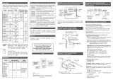
6.2 Connecting the BR323 indicator to a PC
Connect the supplied interconnecting cable
between the programming plug on the front of the
BR323 indicator and the COM port on the personal
computer as shown in Fig 6. The BR323AL or
BR323SS indicator must be connected to an
adjustable 4/20mA signal during conditioning and
calibration, this may be a 4/20mA calibrator or the
indicator may remain in the measurement loop.The
supplied serial connection cable does not provide
isolation, we therefore recommend that either the
4/20mA loop or the personal computer is
unearthed. Using a battery powered 4/20mA
calibrator or a battery powered laptop computer will
avoid earth loop problems.
Fig 6 Connections for conditioning & calibrating a
BR323
6.3 Calibration screen
To run the configuration software click Program in
the PC Start menu and select BEKA Associates;
BR323 Configuration Program followed by BR323
Configuration Program. The BEKA configuration
software has an easy to use calibration screen that
shows the status of the BR323 indicator and
enables the required calibration parameters to be
entered, as shown in Fig 7.
The left hand side of the screen shows the
indicator serial number and its current conditioning
and calibration. The right hand side of the screen
is for entering new conditioning and calibration
information and has two alternative tabs;
Input/Output for linear calibration and Custom
Curve for non-linear calibration such as a square
root extracting curve. With the BR323 indicator
connected as shown in Fig 6 the Connection panel
at the lower left hand side of the screen will show
when the PC has established communication with
the BR323 indicator.
8
6.4 Linear calibration
With the indicator connected to the PC as shown in
Fig 6 and communication established, proceed as
follows:
(1) Right hand side tab
Click the Input / Output tab which will produce
the screen shown in Fig 7.
(2) Linearisation Mode
Set to Normal for linear calibration
(3) Filter
Select frequency of local mains supply to obtain
the maximum interference rejection.
(4) Tag
Up to 16 upper and lower case alphanumeric
characters may be entered to identify the
instrument. This identification only appears on
the Configuration Programme screen not on the
instrument display.
(5) Display Resolution
Defines the number of digits displayed by the
indicator after the decimal point. None,
One, Two or Three digits may be selected,
alternatively selecting Auto instructs the
indicator to display the maximum number of
digits possible after the decimal point which will
vary as the indicator display changes.
Note: Display Resolution does not affect the
Configuration Programme Screen that always
shows a fixed number of digits after the decimal
point.
(6) Input Settings panel
Defines the input current at which the zero
value display and the full value display are
defined which is normally 4 and 20mA. These
figures may be typed into the relevant boxes or
clicking the Capture Zero or Capture Full
buttons will automatically enter the current
actually flowing into the indicator input
terminals. This feature is useful when a
complete loop is being calibrated.
Fig 7 BEKA Configuration Programme Screen
9
(7) Display Settings panel
Defines the indicator display at zero value and
full value input current, which is normally 4 and
20mA.
Note: Irrespective of the selected Display
Resolution, this panel always shows two digits
after the decimal point.
(8) Damping Time
A damping time between 0 and 30 seconds may
be typed into this box. A long damping time will
help to provide a steady display from a noisy
input current.
(9) Units of measurement
The Units of Measurement panel enables a five
digit upper case alphanumeric legend to be
entered which appears below the main indicator
display. This may be used to show the
instrument’s units of measurement or
application.
(10) Downloading calibration to indicator
Ensure that the connection panel shows that the
BR323 indicator is connected to the personal
computer, then click the download arrow on the
toolbar.
After downloading is complete the left hand side
of the Configuration Programme screen should
show the new calibration information and the
BR323 should have the required display. The
calibration information may be stored or printed
from the PC in the normal way.
6.5 Non-linear calibration
The BEKA configuration software enables non-
linear functions to be downloaded to a BR323
indicator. Any curve that continuously increases
or decreases with between 2 and 128 breakpoints
may be used.
6.6 Square root extraction
Probably the most common non-linear function is a
square root curve that enables a BR323 indicator
to display flow in linear engineering units. A
square root table is included with the BEKA
configuration software. To import the square root
table proceed as follows:
(1) Linearisation mode
Open the BEKA configuration programme and
set the Linearisation Mode to Custom which will
produce the screen shown in Fig 8.
(2) Import file
Click File on the toolbar followed by Import
Custom Curve. In the C\My BEKA Associates
Data\Custom Curves folder select SquareRoot
0-100PCT.csv Click the Open button and the
BEKA configuration software will import the
square root file. The table of 128 x and y values
will be displayed and the graph will show the
square root curve.
Fig 8 Non-linear BEKA Configuration Programme display screen
10
(3) Enter the required indicator display
Type the required BR323 indicator Zero and
Full scale displays into the appropriate panels.
Clicking the Upload button will enter these
figures and they will appear on the graph.
(4) Entering other parameters
Clicking the Input / Output tab will enable the
Filter, Tag, Display Resolution, Damping Time
and Units of Measurement to be entered see
6.4 steps 3, 4, 5, 6 & 9 and Fig 7.
(5) Downloading calibration to indicator
Ensure that the Connection panel shows that
the BR323 indicator is connected to the
personal computer then click the download
arrow on the toolbar.
After downloading is complete the left hand side
of the Configuration Programme Screen should
show the new calibration information and the
BR323 should have the required display. The
calibration information may be stored or printed
from the PC in the normal way.
6.7 Other non-linear curves
Other non-linear curves may be generated by
entering the number of breakpoints required and
manually keying the required x and y values into
the table. Alternatively, a comma delimited csv file
containing the custom curve data may be imported
using the procedure described in section 6.6.
11
7. MAINTENANCE
7.1 Fault finding during commissioning
If a BR323AL or BR323SS fails to function during
commissioning the following procedure should be
followed:
Symptom Cause Solution
No display Incorrect There should be 2.3V
wiring between the +ve &
-ve terminals.
No display Incorrect Check that a current
and no volts wiring or is flowing in the
between no power loop.
+ve & -ve supply.
terminals.
Insufficient Check supply
loop voltage voltage and voltage
to operate drops caused by all
indicator components in the
loop
Indicator Positive The input current
displays Hi over-range is greater than
21.4mA.
Indicator Negative The input current
displays Lo under-range is less than 3.8mA.
Unstable 4/20mA Ensure loop supply
display input has a voltage is sufficient.
large ripple to operate the
content. Indicator.
Ensure that Filter
is set to frequency
of local mains
supply.
Increase indicator
damping time.
7.2 Fault finding after commissioning
ENSURE PLANT SAFETY BEFORE
STARTING MAINTENANCE
Live maintenance is NOT permitted on
flameproof equipment. BR323AL and
BR323SS indicator maintenance should
only be performed in a potentially
hazardous area when an explosive
atmosphere is not present.
If a BR323AL or BR323SS fails after it has been
functioning correctly, the following procedure
should be followed:
Symptom Cause Solution
No display No power Check that a
and no volts supply current is flowing in
between +ve the loop.
& -ve terminals.
Unstable 4/20mA input Check loop supply
display has a large voltage.
ripple.
Ensure that Filter
is set to frequency
of local mains
supply.
Increase indicator
damping.
If this procedure does not reveal the cause of the
fault, it is recommended that the BR323 electronic
assembly is replaced.
Note: while the BR323 electronic assembly is
disconnected the 4/20mA loop will be open circuit.
7.3 Servicing
All standard BR323 electronic assemblies are
interchangeable, and a single spare may be used
to replace any instrument that fails.
We recommend that faulty BR323 electronic
assemblies are returned to BEKA associates or to
our local agent for repair.
7.4 Routine maintenance
The mechanical condition of the instrument and the
electrical calibration should be regularly checked.
The interval between inspections depends upon
environmental conditions. We recommend that
initially instrument calibration should be checked
annually.
12
7.5 Guarantee
Indicators which fail within the guarantee period
should be returned to BEKA associates or our local
agent. It is helpful if a brief description of the fault
symptoms is provided.
7.6 Customer comments
BEKA associates is always pleased to receive
comments from customers about our products and
services. All communications are acknowledged
and whenever possible, suggestions are
implemented.
8. ACCESSORIES
8.1 Pipe mounting kit
The pipe mounting kit comprises a stainless steel
‘U’ bolt that enables the BR323AL and BR323SS
indicators to be mounted onto any pipe with an
outside diameter up to 50mm.
8.2 Tag strip
The BR323AL and BR323SS can be supplied with
tag or applicational information thermally printed
onto a polyester strip secured to the instrument
mounting bracket.
The following can be accommodated:
1 row of 36 alphanumeric characters
1.8mm high.
and
1 row of 18 alphanumeric characters
2.6mm high.
8.3 Tag plate
The BR323AL and BR323SS can be supplied with
a tie-on stainless steel plate etched with customer
specified tag number or application information.
The following can be typically accommodated:
1 row of 7 alphanumeric characters
11mm high.
or 1 row of 11 alphanumeric characters
7mm high.
or 2 rows of 15 alphanumeric characters
5mm high.
  • Page 1 1
  • Page 2 2
  • Page 3 3
  • Page 4 4
  • Page 5 5
  • Page 6 6
  • Page 7 7
  • Page 8 8
  • Page 9 9
  • Page 10 10
  • Page 11 11
  • Page 12 12

BEKA BR323AL User manual

Type
User manual

BEKA BR323AL is a field-mountable, loop-powered indicator designed to display the current flowing in a 4/20mA loop in engineering units. It features a 5-digit display, flameproof construction, and a temporary serial data link for configuration and calibration. The BR323AL is suitable for use in hazardous areas and can be used with gases in groups A, B, and C, and dusts with a minimum ignition temperature of 127°C. With an additional software and accessories, it supports linear, square root, or custom linearization and allows for the entry of a units of measurement legend.

Ask a question and I''ll find the answer in the document

Finding information in a document is now easier with AI