Page is loading ...

Trademarks
CTS is a registered trademark of Connection Technology Systems
Inc. Contents subject to revision without prior notice.
All other trademarks remain the property of their owners.
Copyright Statement
Copyright Connection Technology Systems Inc.
This publication may not be reproduced as a whole or in part, in
any way whatsoever unless prior consent has been obtained from
Connection Technology Systems Inc.
FCC Warning
These devices have been tested and found to comply with the
limits for a Class A digital device, pursuant to Part 15 of the FCC
Rules. These standards are designed to provide reasonable
protection against harmful interference when these devices are
operated in a commercial environment. These devices generate,
use, and can radiate radio frequency energy and may cause
harmful interference to radio communications unless installed in
accordance with this User’s Guide. Operation of these devices in a
residential area is likely to cause harmful interference which will
make the user responsible for the appropriate remedial action at
his / her own expense.
CE Mark Warning
These are Class A products. In a domestic environment these
products may cause radio interference in which case the user will
need to consider adequate preventative methods.
1. Checklist
The package should contain the following items:
-
IPC-3012-PoE++ Media Converter
-
User’s Guide
-
Installation Guide
Please notify your sales representative immediately if any item is
missing or damaged.
As for power adapters, please refer to Section 7 for more detailed
information.
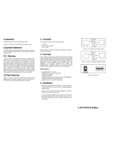
2. Overview
The IPC-3012-PoE++ Ethernet media converter is designed for
industrial applications in the harsh environment. IPC-3012-PoE++
provides 1x10/100/1000Base-T PoE Ethernet port and
1x100/1000Base-X SFP optical port to flexibly meet different
network architecture requirements.
With an extended operation temperature range of -40 to 75°C and
ITU-T K.21 enhanced test level up to 6KV surge immunity on the
RJ-45 copper port, it makes the media converter suitable for
industrial applications.
Major Features:
3. Network Installation
Please follow the steps described below and refer to Figure 1 and
2 to complete the network installation.
Attach fiber cable from the Converter to the fiber network.
Attach a UTP cable from the 10/100/1000Base-T network to
the RJ-45 port on the media converter.
Connect the power supply to the Converter and the Power
LED will light up. The TP and SFP LEDs will light up as soon
as if all the cable connections are satisfactory.
4. Terminal Blocks
Terminal Block 1 Power Supply: Two sets of power inputs
ranging from DC 12V~57V, P1 and P2, are offered for power
redundancy purpose. You can use both pairs of power supply for
redundancy purpose or use either one pair of power supply on this
terminal block and AC external power supply to create redundant
setup. The redundant power supply will take over seamlessly
when one power source is down to protect your device or network
from the loss of power. When you use only one power supply, no
redundant power will be available. Please refer to the following
figure to insert the negative/positive DC wires into the V-/V+
terminals as indicated. (ATTENTION: For high power input devices,
please use the 14AWG or better power wire to connect to the
power input contact.)
Figure 3. Terminal Block 1 Top View
Terminal Block 2 Fault Alarm: One pair of fault connection on
the terminal block 2 is used to connect alarm devices such as
speakers or LEDs to alert users when the port link disconnects
and power failure occurs. (NOTE: Alarm Contact capacity
1A@30V)
-
Provide one Gigabit RJ-45 Copper Port & one SFP Port
100/1000Base-X
-
Compatible with IEEE 802.3af/at PoE+
-
PoE Setting - Auto / Force Power
-
Support 9K Jumbo Frames
-
6KV Surge Immunity on RJ-45 Copper Port (K.21*)
-
Dual Power Input (12~57VDC) &Built-in Power Booster
-
Relay Output for Fault Alarm Notification (Power, Ports)
-
Aluminum Housing
-
Operating Temperature -40ºC~75ºC
P1
Figure 2. IPC-3012-PoE++ Media Converter Top Panel
Use flat-head
screwdriver to
loosen and tighten
the screw.
Figure 1. IPC-3012-PoE++
Media Converter Front
Panel
Use flat-head
screwdriver to
loosen and tighten
the screw.
Figure 4. Terminal
Block 2 Side View
RJ-45 Port
Fiber Port
Terminal Block 2
(For Relay Alarm)
Terminal Block 1
(For Power Input)
Chassis Ground
+
+
P2

5. LED Description
6. DIP SWITCH Setting
The default setting for PIN 1 through PIN 8 is OFF.
NOTE:
1. Before adjusting the configuration of the DIP Switch, the
power should be unplugged.
2. Fiber Mode (PIN 4) only works as Fiber speed (PIN 3) is
set to OFF (1000Mbps). When Fiber speed (PIN 3) is set to
ON (100Mbps), it will ignore the Fiber Mode (PIN 4) setting.
7. Technical Specifications
Standards
IEEE 802.3 10Base-T,IEEE 802.3u 100Base-TX,
IEEE 802.3ab 1000Base-T,IEEE 802.3z
1000Base-X,IEEE802.3af Power over
Ethernet,IEEE802.3at Power over Ethernet
Enhancements
Interface
1 X 10/100/1000Base-T RJ45 (Supports full/half
duplex mode)
1 X 100/1000Base-X SFP
1 X Relay Alarm , Contact capacity 1A@30V
LED
P1, P2, ALM, TP, PoE, and SFP
Power
DC Input Voltage: 12~57VDC
DC Terminal Block with 4 contacts
Shipping Weight
0.62kg
Dimensions
36(W)x110(D)x135(H)mm
Temperature
Operating: -40
o
C~75
o
C; Storage: -40
o
C~85
o
C
Humidity
5%~90% RH non-condensing
EMC Safety
FCC Part 15 Class A, CE
Media
TP:
EIA/TIA-568 CAT 5e
Fiber:
50/125, 62.5/125um multi-mode fiber
9/125, 10/125um single-mode fiber
*Please contact us for further reports and updates.
NOTE: Specifications may change without prior notice.
Contact Information
Connection Technology Systems INC (CTS)
18F-6, No.79, Sec.1, Xintai 5th Rd., Xizhi Dist.,
New Taipei City 221, TAIWAN, R.O.C.
TEL: +886 2 26989661 FAX: +886 2 26989662
IPC-3012-PoE++
10/100/1000Base-T
to 100/1000Base-X
PoE/PSE Media Converter
User’s Guide
Version 1.2
LED
Color
Function
P1, P2
(Power)
Green
Power is available.
ALM
OFF
No alarm occurs.
Red
Lit when Port link is down or power failure
occurs.
Blinking when system boot fails.
TP
OFF
TP port link is down.
Green
Lit when TP 1000M port link is up.
Blinking when TP port is receiving and
transmitting data at the speed of 1000M.
Orange
Lit when TP 10/100M port link is up.
Blinking when TP port is receiving and
transmitting data at the speed of 10/100M.
PoE
OFF
No PSE(Power Sourcing Equipment) exists.
Green
Detect whether power (Max. Power: 30 W) is
supplied through TP port or not. (Auto Mode)
Orange
Enforce to supply 60W power through TP
port.(Force Mode)
SFP
Green
Lit when Fiber 1000M port link is up.
Blinking when Fiber port is receiving and
transmitting data at the speed of 1000M.
Orange
Lit when Fiber 100M port link is up.
Blinking when Fiber port is receiving and
transmitting data at the speed of 100M.
PIN
No.
Function
OFF
ON
1.
External Port Link Alarm
Disable
Enable
2.
External Power Failure Alarm
Disable
Enable
3.
Fiber Speed
1000Mbps
100Mbps
4.
Fiber Mode
Auto-Negoti
ation Mode
Force Mode
5.
N/A
Always Keep OFF
6.
N/A
Always Keep OFF
7.
TP Port PoE Configure
Auto Mode
Force Mode
8.
N/A
Always Keep OFF
/