
Trademarks
CTS is a registered trademark of Connection Technology Systems Inc.. Contents subject to revision without
prior notice. All other trademarks remain the property of their owners.
Copyright Statement
Copyright Connection Technology Systems Inc.
This publication may not be reproduced as a whole or in part, in any way whatsoever unless prior consent
has been obtained from Connection Technology Systems Inc..
FCC Warning
These Media Converters have been tested and found to comply with the limits for a Class A digital device,
pursuant to Part 15 of the FCC Rules. These standards are designed to provide reasonable protection
against harmful interference when these devices are operated in a commercial environment. These devices
generate, use, and can radiate radio frequency energy and may cause harmful interference to radio
communications unless installed in accordance with this User’s Guide. Operation of these devices in a
residential area is likely to cause harmful interference which will make the user responsible for the
appropriate remedial action at his / her own expense.
CE Mark Warning
These are Class A products. In a domestic environment these products may cause radio interference in
which case the user will need to consider adequate preventative methods.
1. Checklist
The package should contain the following items:
CD(User’s Manual and MIB file)
Power Adapter (Optional)*
User’s Guide and Installation Guide
*For detailed information, please see Section 9
Please notify your sales representative immediately if any item is
missing or damaged.
2. Overview
WPC-3112/MPC-3112 Series Media Converters support
IEEE802.3at PoE feature and are specifically designed to supply
power to PoE-enabled devices such as WiFi AP or surveillance
cameras. They are power supply equipment (PSE) that can
transmit data and supply power at the same time to the powered
devices (PD). The maximum cable distance that can reach the
powered devices from WPC-3112/MPC-3112 is up to 100M,
allowing your powered devices to be installed in a place where
power is not easily accessible.
Besides, WPC-3112/MPC-3112 Series Media Converters aim at
industrial applications that demand wide range of operating
temperature and require redundant power supplies to create a
reliable and stable networking environment in the event of power
failure. They can also be mounted on the wall or onto 35mm DIN
rail using DIN rail clip on the media converters. The installation
and operation procedures are simple and straightforward.
Operation status can be locally monitored through a set of
diagnostic LED indicators located on the front panel.
Major Features:
Support IEEE 802.3, 802.3u, 802.3ab, 802.3z, 802.3x, 802.3at
standards
Auto-Negotiation in TP port
Store and Forward Switching Mechanism
Support MDI/MDIX Auto-Crossover
Support fault alarms for power and port failures
Support 9K bytes Jumbo Frame
Support 32k bytes Memory Buffer
Support redundant AC and DC power supply
Support wide range of operating temperature (-20
o
C ~60
o
C)
Support DIN Rail and Wall Mounting
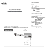
3. Network Installation
Attach fiber cable from the Converter to the fiber network.
Attach a UTP cable from the 10/100/1000Base-TX network to
the RJ-45 port on the Converter.
Connect the power adapter to the Converter and check that the
Power LED lights up. The TP Link/ACT and F/O Link/ACT LED
will light when all the cable connections are satisfactory.
Figure 1. Basic Network Connection for BTFX models.
Figure 2. Basic Network Connection for WDM/SFP models
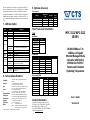
4. DIP SWITCH Setting
WPC-3112/MPC-3112 Series Media Converters provide users
with a DIP Switch to configure switching functions. The DIP Switch
is located at the bottom panel of the media converter, and the
default setting of all pins is OFF.
MPC-3112 WPC-3112
Figure 3. Terminal Block and DIP Switch (Bottom Panel)
Auto-Negotiation
(Pin 2 OFF)
100 M (Pin 1 OFF)
1000M (Pin 1 ON)
NOTE: 1. Pin 1 and 2 must be set together to configure the speed.
2. Before changing duplex mode and flow control setting,
please make sure not to set Pin 1 and 2 to OFF.
3. Under 1000Mbps, it supports full-duplex mode only.
4. When setting Pin 7 to ON and TP speed to 1000M,
full-duplex mode and flow control are disabled.
5. Terminal Block
TB1 and TB2 Power Supply: There are two pairs of power
supply connection (TB1 and TB2) on the terminal block for
power redundancy purpose. You can use both pairs of power
supply (TB1 and TB2) or use either one pair of power supply on
the terminal block and AC external power supply to create
redundant setup. The redundant power supply will take over
seamlessly when one power source is down to protect your
device or network from the loss of power. When you use only
one power supply (no redundant power is available), the LED
Power/Port Status will flash in orange to alert the user.
Port Fault Alarm: One pair of port fault connection on the
terminal block is used to connect alarm devices such as
speakers or LEDs to alert users when TP or F/O port link is
disconnected. To make this function work, you must first set pin
8 and 9 on the DIP Switch to ON position (Enable).
Figure 4. Terminal Block Front and Top View
6. Link Alarm
Link Alarm allows users to easily identify and diagnose the linking
status. If Link Alarm DIP switch is set to Enable, TP and F/O can
link up only when both linking conditions are good. In addition, if
the TP or F/O port link is down during operation, the other port will
Use flat-head
screwdriver to
loosen and tighten
the screw.
Insert positive or
negative wire as
indicated.


 1
1
 2
2


 Articona 585688 User manual
Lantech CM-121 User manual
LevelOne GVT-2010 User manual
Repotec RP-PEG08-H Owner's manual
Clinton Electronics CE-PSG-5088V User manual
 Wi-Tek WI-PS306GF-I Installation guide
Perle S-1110HP-SFP Owner's manual
Allnet ALL8845PD User guide

