Page is loading ...

iConverter
®
5 Port GM4 PoE+ and HPoE
Network Interface Devices
Quick Start Guide
38 Tesla, Irvine, CA 92618 USA
Phone: (949) 250-6510; Fax: (949) 250-6514
General and Copyright Notice
This publication is protected by U.S. and international copyright laws. All rights
reserved. The whole or any part of this publication may not be reproduced, stored
in a retrieval system, translated, transcribed, or transmitted, in any form, or by
any means, manual, electric, electronic, electromagnetic, mechanical, chemical,
optical or otherwise, without prior explicit written permission of Omnitron Systems
Technology, Inc.
The following trademarks are owned by Omnitron Systems Technology, Inc.:
FlexPoint
TM
, FlexSwitch
TM
, HybridNID
®
, iConverter
®
, miConverter
TM
, NetOutlook
®
,
OmniLight
®
, OmniConverter
®
, RuggedNet
®
, Omnitron Systems Technology, Inc.
TM
,
OST
TM
and the Omnitron logo.
All other company or product names may be trademarks of their respective owners.
The information contained in this publication is subject to change without notice.
Omnitron Systems Technology, Inc. is not responsible for any inadvertent errors.
Warranty
This network product and the included AC/DC power adapter are warranted to the
original purchaser (Buyer) against defects in material and workmanship for a period
of two (2) years from the date of shipment. The warranty for the network product can
be extended to three (3) years by registering the product at www.omnitron-systems.
com/support within ninety (90) days from the date of shipment. During the warranty
period, Omnitron will, at its option, repair or replace a product which is proven to be
defective with the same product or with a product with at least the same functionality.
For warranty service, the product must be sent to an Omnitron designated facility,
at Buyer’s expense. Omnitron will pay the shipping charge to return the product
to Buyer’s designated US address using Omnitron’s standard shipping method.
Limitation of Warranty
The foregoing warranty shall not apply to product malfunctions resulting from
improper or inadequate use and/or maintenance of the equipment by Buyer, Buyer-
supplied equipment, Buyer-supplied interfacing, unauthorized modications or
tampering with equipment (including removal of equipment cover by personnel not
specically authorized and certied by Omnitron), or misuse, or operating outside
the environmental specication of the product (including but not limited to voltage,
ambient temperature, radiation, unusual dust, etc.), or improper site preparation
or maintenance.
No other warranty is expressed or implied. Omnitron specically disclaims the implied
warranties of merchantability and tness for any particular purpose.
The remedies provided herein are the Buyer’s sole and exclusive remedies. Omnitron
shall not be liable for any direct, indirect, special, incidental, or consequential
damages, whether based on contract, tort, or any legal theory.
Page 2

Environmental Notices
The equipment covered by this manual must be disposed of or recycled in
accordance with the Waste Electrical and Electronic Equipment Directive (WEEE
Directive) of the European Community directive 2012/19/EU on waste electrical and
electronic equipment (WEEE) which, together with the RoHS Directive 2015/863/
EU, for electrical and electronic equipment sold in the EU after July 2019. Such
disposal must follow national legislation for IT and Telecommunication equipment
in accordance with the WEEE directive: (a) Do not dispose waste equipment with
unsorted municipal and household waste. (b) Collect equipment waste separately.
(c) Return equipment using collection method agreed with Omnitron.
The equipment is marked with the WEEE symbol shown to indicate that it
must be collected separately from other types of waste. In case of small items the
symbol may be printed only on the packaging or in the user manual. If you have
questions regarding the correct disposal of equipment go to www.omniton-systems.
com/support or e-mail to Omnitron at [email protected].
Safety Warnings and Cautions
ATTENTION: Observe precautions for handling electrostatic discharge
sensitive devices.
WARNING: Potential damage to equipment and personal injury.
WARNING: Risk of electrical shock.
iConverter
®
5 Port GM4 PoE+ and HPoE
Quick Start Guide
Product Overview
The GM4-PoE+ and GM4-HPoE Network Interface Devices (NID) deliver advanced
Carrier Ethernet 2.0 services and provide integrated Power over Ethernet (PoE) at
the demarcation. The GM4 PoE NIDs enables rapid service deployments, Service
Level Agreement (SLA) assurance and protection switching. GM4 PoE NIDs can
function as PoE Power Sourcing Equipment in Small Cell (metro cell), WiFi and
other PoE applications.
GM4-PoE+ and GM4-HPoE models support 802.3af PoE (15.4W) and 802.3at PoE+
(25.5W) on each RJ-45 port. The GM4-HPoE models also provide up to 60W of
power to access points for hot spot and metro cell applications.
Power over Ethernet Pins
IEEE 802.3af and 802.3at
Alternate B
Vport Positive - pins 4,5
Vport Negative - pins 7,8
High Power over Ethernet
4 Pair Powering
Vport Positive - pins 3,6 and 4,5
Vport Negative - pins 1,2 and 7,8
PoE Pinout Conguration
The GM4-PoE+ and GM4-HPoE support carrier-class Ethernet Service OAM
standards. IEEE 802.1ag Connectivity Fault Management (CFM) proactively
monitors service availability and provides tools for rapid fault isolation. ITU-T Y.1731
adds Performance Monitoring to monitor key SLA parameters including frame delay,
frame delay variation, and frame loss.
For Ethernet Service Activation Testing, the GM4 supports ITU-T Y.1564 and IETF
RFC 2544. The GM4 can also be congured to respond to 3rd party test equipment
(JDSU and VeEX) and initiate or respond to RFC 5357 Two-Way Active Measurement
Protocol (TWAMP) protocol.
To access the user manuals for the Menu Interface (xxxxUM-02x Menu
Interface iConverter GM4 NIDs) and Command Line Interface (xxxxUM-01x
Command Line Interface iConverter GM4 NIDs), access the product pages at: www.
omnitron-systems.com.
Recovering Access to the GM4
In the event the username and/or password is unknown, the GM4 will revert to its
factory default username and password for 60 seconds after a power cycle. Using
the factory default IP address, username and password, access the GM4. A recovery
prompt will be displayed, allowing the username and/or password to be modied.
Front Panel
The front of the GM4 provides access to the RJ-45 and SFP ports. The SFP ports
support 100/1000BASE-X SFP ber and 10/100/1000BASE-T copper transceivers.
The serial console (management) is accessed from the rear of the module.
Page 3
Page 4

Page 5
5-Port GM4 PoE Front Panel Layout
Serial Console Port
To congure the GM4 PoE NID using the serial port, attach a DB-9 serial (RS-232)
equipped computer with terminal emulation software such as Procomm or Putty to
the serial port on the GM4 PoE NID using the included cable. The Serial Console
Port (DCE) is a RJ-45 connector (per EIA/TIA-561) which can be changed to a DB-9
connector with the included cable.
The serial console port is located on the back of the module. Attach the ends of a
serial adapter cable to the serial port of the PC and the RJ-45 connector of the GM4
PoE NID. The port is a standard RS-232 asynchronous serial interface.
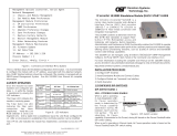
The serial adapter cable pin-outs are illustrated below.
Serial Adapter Cable Pin Outs
Some computers do not come with DB-9 serial port connectors and may require a
USB-to-serial port adapter.
The port is a standard RS-232 asynchronous serial interface. The serial ports is
congured for 57,600bps, 1 stop, 8 data, parity none.
RJ-45 and SFP Ports
The RJ-45 Ethernet ports support 10BASE-T, 100BASE-TX and 1000BASE-T
protocols, auto-negotiation, auto MDI/MDI-X crossover and can be manually forced
to a specic speed and duplex mode. The RJ-45 Ethernet ports support IEEE
802.3af and IEEE 802.3at PoE standards providing up to 12.95W or 25.5W of DC
Page 6
power to each Powered Device port. The GM4-HPoE models support up to 60W
of DC power on each port.
The SFP interfaces support SERDES 100BASE-FX or 1000BASE-X ber transceivers
and SGMII 10/100/1000BASE-T copper transceivers. The SFP interfaces operate
in manual mode or auto-negotiation and support full duplex operation.
NOTE: When using 100BASE-FX SGMII SFPs, the port must be manually
congured using the Command Line Interface (CLI). Interface settings can
be changed using the port command.
All ports can be enabled or disabled via network management. A port disabled with
Port Access Control Setup will still connect and allow 802.3ah Link OAM monitoring,
but blocks normal data trafc.
Installation Procedure
1) Congure DIP-switches
2) Installing the Module
3) Apply Power
4) Connect Cables
5) Verify Operation
1) Congure DIP-switches
The GM4 has two banks of DIP-switches. The location of the DIP-switches is
illustrated below.
DIP-switch Location

Page 7
DIP-switch Bank 1 Settings:
The function of DIP-switch Bank 1 is outlined in the table below.
PoE+ Models
Switch
Position
1 Fiber + 1 UTP 1 Fiber + 4 UTP 2 Fiber + 2 UTP 2 Fiber + 3 UTP
1 Reserved Reserved Reserved Reserved
2 Reserved Reserved Reserved Reserved
3 Reserved Reserved Reserved Reserved
4 Reserved Reserved Reserved Reserved
5 Reserved Reserved Return to Primary Return to Primary
6 Reserved Reserved Redundancy Redundancy
7 Reserved Reserved Reserved Reserved
8 Zero Touch Zero Touch Zero Touch Zero Touch
DIP-switch Bank 1 Description for PoE+ Models
HPoE Models
Switch
Position
1 Fiber + 1 UTP 1 Fiber + 4 UTP 2 Fiber + 2 UTP 2 Fiber + 3 UTP
1 Port 2 60W PoE Port 2 60W PoE Reserved Reserved
2 Reserved Port 3 60W PoE Port 3 60W PoE Port 3 60W PoE
3 Reserved Port 4 60W PoE Port 4 60W PoE Port 4 60W PoE
4 Reserved Port 5 60W PoE Reserved Port 5 60W PoE
5 Reserved Reserved Return to Primary Return to Primary
6 Reserved Reserved Redundancy Redundancy
7 Reserved Reserved Reserved Reserved
8 Zero Touch Zero Touch Zero Touch Zero Touch
DIP-switch Bank 1 Description for HPoE Models
SW1, SW2, SW3, SW4 - Reserved (All PoE+ Models)
These DIP-switches are reserved and must be in the DOWN (default) position.
SW1, SW2, SW3, SW4 - HPoE Power (All HPoE Models)
60W PoE power application can be automatically detected with the attached PD
when the corresponding port DIP-switch is in the “Auto” (factory default) DOWN
position. When the corresponding DIP-switch is in the “60W Forced” UP position,
the power is available without detecting the 60W PoE capability of the attached
PD. See DIP-switch Bank 1 Description for HPoE Models above for the proper
port conguration.
SW1 - SW4 Function
Auto (DOWN) Automatically detects the power requirement of the attached PD
60W Forced (UP) 60W Power is available without detecting the 60W PoE capability of the attached PD
HPoE SW1 - SW4 Function
Page 8
NOTE: 60W Forced option will supply only the amount of power required by
the PD and only up to 60 watts per port. When congured for 60W Forced,
power will be applied unless an OPEN or SHORT condition is detected on
the connected port.
SW5, SW6 - Reserved (All One Fiber Port PoE+ and HPoE Models)
These DIP-switches are reserved and must be in the DOWN (default) position.
SW5, SW6 - Port Redundancy (All Two Port Fiber PoE+ and HPoE Models)
DIP-switches SW5 and SW6 congure the device for port redundancy. When
congured for port redundancy, the device will transmit and receive trafc on the
primary port (Port 1) and no trafc on the backup port (Port 2). When a ber failure
occurs on the primary port, the device will switch over to the backup port within
50msec.
NOTE: 50msec failover is only supported on the P1 and P2 ber ports.
Port Redundancy
DIP-switches SW5 and SW6 control the port redundancy mode of the device.
When SW6 is in the “Off” (factory default) DOWN position, the ports operate in a
non-redundant (independent) mode. When SW6 is in the “On” UP position, the
device is congured for port redundancy and operates based on the position of SW5.
When SW5 is in the “Off” (factory default) DOWN position, the device will switch
back to the primary port (Port 1) once a stable connection has been established.
When SW5 is in the “On” UP position, the device will remain on the backup port
(Port 2) even when a stable connection has been established on Port 1. See Port
Redundancy Modes table for more information.
NOTE: The ports must have MAC learning disabled to perform a 50msec
switch over.
SW5 SW6 Function
Off (DOWN) Off (DOWN) Non-redundant mode - independent mode
On (UP) Off (DOWN) Non-redundant mode - independent mode
Off (DOWN) On (UP) Redundant mode - return to primary (RTP)
On (UP) On (UP) Redundant mode - no return to primary
Port Redundancy Modes
SW7 - Reserved (All PoE+ and HPoE Models)
This DIP-switch is reserved and must be in the DOWN (default) position.

Page 9
SW8 - Zero Touch Provisioning
Zero Touch Provisioning (ZTP) utilizes DHCP and TFTP to automatically congure
the device during the initial setup.
Zero Touch is disabled by default. The ZTP process is congured by setting this
DIP-switch to the Up position (enabled). When ZTP is enabled, the device will start
the DHCP process on power up or device reboot. During the process, the device
will request the IP address of the TFTP Server. After the DHCP process has been
completed and a TFTP Server IP address has been obtained, the device will request
conguration les from the TFTP Server. When the les have been received, the
device will load the conguration les and restart.
2) Installing the Module
Wall Mounting
The wall mounting height of the module should be less than or equal to 2 meters
(6.6 feet) from the oor. Use the four mounting holes on the module to secure the
module to the wall. The module can accommodate #6 screws (not included).
Installation of the module should be such that the air ow in the front, back, side
and top vents of the switch are not compromised or restricted.
The accessory cables should have their own strain relief and do not pull down on
the module.
Rack Mounting
The standalone modules with integrated mounting brackets or using the optional
mounting bracket kit can be rack mounted using the optional Rack Mount Shelf
(8260-0). Refer to the Rack Mount Shelf user manual (040-08260-001x) for the
proper installation guidelines.
Follow the same guidelines above when rack mounting the module.
3) Apply Power
AC Power
Secure the ground wire to the ground screw located on the back of the module.
Route the power cord through the provided strain relief for additional support and
connect the barrel/DIN connector at the end of the wire on the AC/DC adapter to
the barrel connector on the module. Connect the AC/DC adapter to the AC outlet.
Conrm that the module has powered up properly by checking the Power LED
located on the front of the module.
Page 10
AC Models Rear View: Barrel/DIN Connector for AC/DC Power Adapter
NEVER ATTEMPT TO OPEN THE CHASSIS OR
SERVICE THE POWER SUPPLY. OPENING THE
CHASSIS MAY CAUSE SERIOUS INJURYOR DEATH.
THERE ARE NO USER REPLACEABLE OR
SERVICEABLE PARTS IN THIS UNIT.
WARNING!!!
DC Power
This module is intended for installation in restricted access areas. (“Les matériels
sont destinés à être installés dans des EMPLACEMENTS À ACCÈS RESTREINT”).
A restricted access area can be accessed only through the use of a special key, or
other means of security.
The over current protection for connection with centralized DC shall be provided in
the building installation, and shall be a UL listed circuit breaker rated 20 Amps, and
installed per the National Electrical Code, ANSI/NFPA-70.
Appropriate overloading protection should be provided on the DC power source
outlets utilized.
The GM4-PoE+ requires +/-48 to +/-57VDC inclusive of tolerances (48VDC @ 2.74
Amp max rated power when powering four PoE+ PDs). The GM4-HPoE requires
+/-48 to +/-57VDC inclusive of tolerances (48VDC@ 5.24 Amp max rated power
when powering four 60W PoE PDs). See specication table for specic model
requirements.
Appropriate overloading protection should be provided on the DC power source
outlets utilized.
DC Models Rear View: 3-Pin Terminal for DC Power

Page 12
WARNING: OnlyaDC power source that complies with
safety extra low voltage (SELV) requirements can be
connected to the DC-input power supply.
WARNING REGARDING EARTHING GROUND:
o
o
o
o
This equipment shall be connected to the DC supply
system earthing electrode conductor or to a bonding
jumper from an earthing terminal bar or bus to which the
DC supply system earthing electrode is connected.
This equipment shall be located in the same immediate
area (such as adjacent cabinets) as any other equipment
that has a connection between the earthed conductor of
the same DC supply circuit and the earthing conductor,
and also the point of earthing of the DC system. The DC
system shall not be earthed elsewhere.
The DC supply source is to be located within the same
premises as this equipment.
There shall be no switching or disconnecting devices in
the earthed circuit conductor between the DC source and
the earthing electrode conductor.
Locate the DC circuit breaker of the external power source, and switch the circuit
breaker to the OFF position.
Prepare a power cable using a three conductor insulated wire (not supplied) with
12AWG to 14AWG thickness. Cut the power cable to the length required.
Strip approximately 3/8 of an inch of insulation from the power cable wires.
Connect the power and ground cables to the module by fastening the stripped ends
to the DC power connector.
WARNING: The positive lead of the power source must be connected to the
“+” terminal on the module, the negative lead of the power source to the “-“
terminal on the module and ground lead to ground.
Power Options
WARNING: Note the wire colors used in making the positive, negative and
ground connections. Use the same color assignment for the connection at
the circuit breaker.
Connect the power wires to the circuit breaker and switch the circuit breaker ON.
If any module are installed, the Power LED will indicate the presence of power.
During the installation, ensure that the ground potentials are maintained throughout
the system connections. This includes but not limited to the power source ground
and any shielded cabling grounds.
Page 11
NEVER ATTEMPT TO OPEN THE CHASSIS OR
SERVICE THE POWER SUPPLY. OPENING THE
CHASSIS MAY CAUSE SERIOUS INJURYOR DEATH.
THERE ARE NO USER REPLACEABLE OR
SERVICEABLE PARTS IN THIS UNIT.
WARNING!!!
Make sure to disconnect the power and ground cables before removing the
equipment.
4) Connect Cables
a. When using SFP models, insert the SFP ber transceiver into the SFP
receptacle on the front of the module (see the SFP Data Sheet 091-17000-001
for supported Fast/Gigabit transceivers).
NOTE: The release latch of the SFP ber transceiver must be in the closed
(up) position before insertion.
The module has the ability to detect the speed and automatically congure
the port to match the speed of approved SFP transceivers. Some SFP ber
transceivers will need to be congured using the portattribute CLI commands
to congure the speed of the port to match the speed of the installed SFP
transceiver.
b. Connect an appropriate multimode or single-mode ber cable to the ber port
on the front of the module. It is important to ensure that the transmit (TX) is
attached to the receive side of the transceiver at the other end and the receive
(RX) is attached to the transmit side. When using single-ber (SF) models, the
TX wavelength must match the RX wavelength at the other end and the RX
wavelength must match the TX wavelength at the other end.
c. Connect the Ethernet 10/100/1000 RJ-45 port using a Category 5 or better
cable to an external 10BASE-T, 100BASE-TX or 1000BASE-T Ethernet device.
d. The contact closure is located on the back of the module and is used to detect
the state of external alarm conditions. The contact closure can detect if the
wired circuit is open or closed. The change of state of the contact closure (open/
close) will generate a SNMP trap. Use the supplied connector to attach the
wire to the external alarm. Use 16 - 24 AWG wire.
Contact Closure Example
WARNING: Never apply an active circuit or voltage to the contact closure pins.

Page 13 Page 14
5) Verify Operation
Once the module has been installed and the DIP-switches have been congured,
verify the module is operational by viewing the status of the LED indicators.
The Power LEDs indicate the module is receiving power from the external power
source.
The port LEDs indicate the state of connection between link partners. A blinking
port activity LED indicates the presence of data.
The PSE LEDs indicate the state of the PoE power. A solid green PSE LED
indicates sufcient PoE power to the device. A solid amber PSE LED indicates a
PSE power error.
PSE Error conditions
Over current: When the PD consumes more power than it has negotiated.
Brownout: When the available power is insufcient to full the requested
PD power load.
Insufcient Power: When the requested power is less than the capability of the
power supply.
PD: When the heartbeat function is enabled and the consecutive
lost heartbeats exceed the congured value.
LED Function
“Legend”
Color
OFF State ON/Blinking State
Power
“PWR”
Green No power ON: Module has power
P1 Link Activity
“100”
Green Port not linked at 100M
ON: Port linked at 100M
Blinking: Data activity
P1 Link Activity
“1G”
Green Port not linked at 1000M
ON: Port linked at 1000M
Blinking: Data activity
P1 Link Activity
“100” and “1G”
Green Port not linked at 10M
ON: Port linked at 10M
Blinking: Data activity
P2 Link Activity
“100”
Green Port not linked at 100M
ON: Port linked at 100M
Blinking: Data activity
P2 Link Activity
“1G”
Green Port not linked at 1000M
ON: Port linked at 1000M
Blinking: Data activity
P2 Link Activity
“100” and “1G”
Green Port not linked at 10M
ON: Port linked at 10M
Blinking: Data activity
P2 PoE Status
“PSE”
Green/
Amber
Port not providing PoE power
Solid Green: Port is providing PoE
power to the PD
Solid Amber: PoE error
1 + 1 LED Indicates
LED Function
“Legend”
Color OFF State ON/Blinking State
Power
“PWR”
Green No power ON: Module has power
P1 Link Activity
“100”
Green Port not linked at 100M
ON: Port linked at 100M
Blinking: Data activity
P1 Link Activity
“1G”
Green Port not linked at 1000M
ON: Port linked at 1000M
Blinking: Data activity
P1 Link Activity
“100” and “1G”
Green Port not linked at 10M
ON: Port linked at 10M
Blinking: Data activity
P2 Link Activity
“100”
Green Port not linked at 100M
ON: Port linked at 100M
Blinking: Data activity
P2 Link Activity
“1G”
Green Port not linked at 1000M
ON: Port linked at 1000M
Blinking: Data activity
P2 Link Activity
“100” and “1G”
Green Port not linked at 10M
ON: Port linked at 10M
Blinking: Data activity
P2 PoE Status
“PSE”
Green/
Amber
Port not providing PoE power
Solid Green: Port is providing PoE
power to the PD
Solid Amber: PoE error
P3 Link Activity
“100”
Green Port not linked at 100M
ON: Port linked at 100M
Blinking: Data activity
P3 Link Activity
“1G”
Green Port not linked at 1000M
ON: Port linked at 1000M
Blinking: Data activity
P3 Link Activity
“100” and “1G”
Green Port not linked at 10M
ON: Port linked at 10M
Blinking: Data activity
P3 PoE Status
“PSE”
Green/
Amber
Port not providing PoE power
Solid Green: Port is providing PoE
power to the PD
Solid Amber: PoE error
P4 Link Activity
“100”
Green Port not linked at 100M
ON: Port linked at 100M
Blinking: Data activity
P4 Link Activity
“1G”
Green Port not linked at 1000M
ON: Port linked at 1000M
Blinking: Data activity
P4 Link Activity
“100” and “1G”
Green Port not linked at 10M
ON: Port linked at 10M
Blinking: Data activity
P4 PoE Status
“PSE”
Green/
Amber
Port not providing PoE power
Solid Green: Port is providing PoE
power to the PD
Solid Amber: PoE error
P5 Link Activity
“100”
Green Port not linked at 100M
ON: Port linked at 100M
Blinking: Data activity
P5 Link Activity
“1G”
Green Port not linked at 1000M
ON: Port linked at 1000M
Blinking: Data activity
P5 Link Activity
“100” and “1G”
Green Port not linked at 10M
ON: Port linked at 10M
Blinking: Data activity
P5 PoE Status
“PSE”
Green/
Amber
Port not providing PoE power
Solid Green: Port is providing PoE
power to the PD
Solid Amber: PoE error
1 +4 LED Indicators

Page 15
Page 16
LED Function
“Legend”
Color OFF State ON/Blinking State
Power
“PWR”
Green No power ON: Module has power
P1 Link Activity
“100”
Green Port not linked at 100M
ON: Port linked at 100M
Blinking: Data activity
P1 Link Activity
“1G”
Green Port not linked at 1000M
ON: Port linked at 1000M
Blinking: Data activity
P1 Link Activity
“100” and “1G”
Green Port not linked at 10M
ON: Port linked at 10M
Blinking: Data activity
P2 Link Activity
“100”
Green Port not linked at 100M
ON: Port linked at 100M
Blinking: Data activity
P2 Link Activity
“1G”
Green Port not linked at 1000M
ON: Port linked at 1000M
Blinking: Data activity
P2 Link Activity
“100” and “1G”
Green Port not linked at 10M
ON: Port linked at 10M
Blinking: Data activity
P3 Link Activity
“100”
Green Port not linked at 100M
ON: Port linked at 100M
Blinking: Data activity
P3 Link Activity
“1G”
Green Port not linked at 1000M
ON: Port linked at 1000M
Blinking: Data activity
P3 Link Activity
“100” and “1G”
Green Port not linked at 10M
ON: Port linked at 10M
Blinking: Data activity
P3 PoE Status
“PSE”
Green/
Amber
Port not providing PoE power
Solid Green: Port is providing PoE
power to the PD
Solid Amber: PoE error
P4 Link Activity
“100”
Green Port not linked at 100M
ON: Port linked at 100M
Blinking: Data activity
P4 Link Activity
“1G”
Green Port not linked at 1000M
ON: Port linked at 1000M
Blinking: Data activity
P4 Link Activity
“100” and “1G”
Green Port not linked at 10M
ON: Port linked at 10M
Blinking: Data activity
P4 PoE Status
“PSE”
Green/
Amber
Port not providing PoE power
Solid Green: Port is providing PoE
power to the PD
Solid Amber: PoE error
2 +2 LED Indicators
LED Function
“Legend”
Color OFF State ON/Blinking State
Power
“PWR”
Green No power ON: Module has power
P1 Link Activity
“100”
Green Port not linked at 100M
ON: Port linked at 100M
Blinking: Data activity
P1 Link Activity
“1G”
Green Port not linked at 1000M
ON: Port linked at 1000M
Blinking: Data activity
P1 Link Activity
“100” and “1G”
Green Port not linked at 10M
ON: Port linked at 10M
Blinking: Data activity
P2 Link Activity
“100”
Green Port not linked at 100M
ON: Port linked at 100M
Blinking: Data activity
P2 Link Activity
“1G”
Green Port not linked at 1000M
ON: Port linked at 1000M
Blinking: Data activity
P2 Link Activity
“100” and “1G”
Green Port not linked at 10M
ON: Port linked at 10M
Blinking: Data activity
P3 Link Activity
“100”
Green Port not linked at 100M
ON: Port linked at 100M
Blinking: Data activity
P3 Link Activity
“1G”
Green Port not linked at 1000M
ON: Port linked at 1000M
Blinking: Data activity
P3 Link Activity
“100” and “1G”
Green Port not linked at 10M
ON: Port linked at 10M
Blinking: Data activity
P3 PoE Status
“PSE”
Green/
Amber
Port not providing PoE power
Solid Green: Port is providing PoE
power to the PD
Solid Amber: PoE error
P4 Link Activity
“100”
Green Port not linked at 100M
ON: Port linked at 100M
Blinking: Data activity
P4 Link Activity
“1G”
Green Port not linked at 1000M
ON: Port linked at 1000M
Blinking: Data activity
P4 Link Activity
“100” and “1G”
Green Port not linked at 10M
ON: Port linked at 10M
Blinking: Data activity
P4 PoE Status
“PSE”
Green/
Amber
Port not providing PoE power
Solid Green: Port is providing PoE
power to the PD
Solid Amber: PoE error
P5 Link Activity
“100”
Green Port not linked at 100M
ON: Port linked at 100M
Blinking: Data activity
P5 Link Activity
“1G”
Green Port not linked at 1000M
ON: Port linked at 1000M
Blinking: Data activity
P5 Link Activity
“100” and “1G”
Green Port not linked at 10M
ON: Port linked at 10M
Blinking: Data activity
P5 PoE Status
“PSE”
Green/
Amber
Port not providing PoE power
Solid Green: Port is providing PoE
power to the PD
Solid Amber: PoE error
2 +3 LED Indicators

LED Legend/State
Link Speed
“1G” “100”
OFF OFF Port not linked
OFF ON Port linked at 100Mbps
ON OFF Port linked at 1000Mbps
ON ON Port linked at 10Mbps
Port Speed LED Indicators for all Models
Specications
Description
iConverter GM4-PoE and GM4-HPoE
10/100/1000BASE-TX UTP to 1000BASE-X Fiber
Network Interface Device with Power over Ethernet
Management Telnet, SNMPv1, SNMPv2c, SNMPv3, SSH, Serial Console
Frame Size Up to 10,240 bytes
Port Types
Copper: RJ-45: 10/100/1000BASE-T
Fiber: SFP: 10/100/1000BASE-T SGMII Copper Transceiver
100BASE-X or 1000BASE-X Fiber Transceiver
Serial: RJ-45
Cable Types
Copper: EIA/TIA 568A/B, Cat 5 UTP and higher
Fiber: Multimode: 50/125, 62.5/125µm
Single-mode: 9/125µm
Serial: Category 3 and higher
AC Power Requirements
AC Adapter: 100 - 240VAC/50 - 60Hz,
2.8A @ 120VAC
DC Power Requirements
Terminal: 3-Pin Terminal (isolated)
+/-48 - +/-57VDC inclusive of tolerance
AC Adapter: 2.1mm Barrel Connector
+/-48 - +/-57VDC inclusive of tolerance
1 PoE/PoE+ Port (30W) 0.83A @ 48VDC
2 PoE/PoE+ Ports (60W) 1.50A @ 48VDC
3 PoE/PoE+ Ports (90W) 2.13A @ 48VDC
4 PoE/PoE+ Ports (120W) 2.74A @ 48VDC
1 HPoE Port (60W) 1.45A @ 48VDC
2 HPoE Ports (120W) 2.75A @ 48VDC
3 HPoE Ports (180W) 4.01A @ 48VDC
4 HPoE Ports (240W) 5.24A @ 48VDC
Dimensions
(W x D X H)
5” x 7.5” x 1.375” (127 mm x 190.5 mm x 34.93 mm)
Weight
Module Only: 1.38 lbs. (0.626 kg.)
Module w/ AC adapter: 2.50 lbs. (1.134 kg.)
Operating Temperature
Commercial: 0 to 50°C
Wide: -40 to 60°C (-20°C AC cold start)
Extended: -40 to 75°C (-20°C AC cold start)
Storage: -40 to 80°C
Humidity 5% to 95% (non-condensing)
Altitude -100m to 4,000m (operational)
MTBF (hours)
8991S-11, 8991T-11: 77,258
8991S-14: 73,708
8991T-14: 98,980
8991S-22, 8991T-22: 75,328
8991S-23: 73,918
8991T-23: 99,360
Warranty 3 year warranty
Page 17
Page 18

Standard Compliances
IEEE 802.1Q, 802.1ad, 802.1ax, 802.1p, 802.3, 802.3ad, 802.3ah,
802.1ag, 1588v2
IEEE 802.3af (15.40 watts max), IEEE 802.3at (30 watts max)
High Power 60W PoE
RFC 2819 (RMON), 2863 (IF-MIB), 2131 (DHCP), 2544, 5357
ITU-T G.8031, G.8032, G.8262, Y.1731, Y.1564
MEF 9, 14, 21, 30, 31, Carrier Ethernet 2.0
Regulatory Compliances UL, CE, FCC Class A, NEBS Level 3
Environmental REACH, RoHS and WEEE
Customer Support Information
If you encounter problems while installing this product, contact Omnitron Technical
Support:
Phone: (949) 250-6510
Fax: (949) 250-6514
Address: Omnitron Systems Technology, Inc.
38 Tesla
Irvine, CA 92618, USA
Email: [email protected]
URL: www.omnitron-systems.com
040-8991S-001B 9/20
Page 19
Page 20
/