Page is loading ...

ADAPTIVE
SYSTEM
11/2018 NK9318
V1
Owner’s
Manual
Guide d’utilisation / Manual del propietario
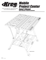
PRODUCTS COVERED IN THIS MANUAL
Versa-Stops
(ACS735)
48" ExtensionRepetitive StopsProject Table
(ACS1000)
Miter Guide
RECOMMENDED TOOLS:
• ¾" Combination Wrench • 15mm Combination Wrench
• Phillips Screwdriver • 10mm Deep Socket
• 15mm Deep Socket • Speed Square
• Ratchet Wrench

GENERAL SAFETY GUIDELINES
WARNING
!
Read all safety warnings, instructions, illustrations and specications provided with this product. Failure to follow all instructions listed
below may result in electric shock, re and/or serious injury. SAVE ALL WARNINGS AND INSTRUCTIONS FOR FUTURE REFERENCE.
The term "power tool" in the warnings refers to your mains-operated (corded)
power tool or battery-operated (cordless) power tool.
NOTE: “Mains” is the ocial UL term for “mains electricity”
referring to grid power delivered to customers and accessed
through a wall outlet.
1) Work area safety
a) Keep work area clean and well lit.
Cluttered or dark areas invite accidents.
b) Do not operate power tools in explosive atmospheres,
such as in the presence of ammable liquids, gases or dust.
Power tools create sparks which may ignite the
dust or fumes.
c) Keep children and bystanders away while operating
a power tool. Distractions can cause you to lose control.
2) Electrical safety
a) Power tool plugs must match the outlet. Never modify the
plug in any way. Do not use any adapter plugs with earthed
(grounded) power tools. Unmodied plugs and matching
outlets will reduce risk of electric shock.
b) Avoid body contact with earthed or grounded surfaces,
such as pipes, radiators, ranges and refrigerators.
There is an increased risk of electric shock if
your body is earthed or grounded.
c) Do not expose power tools to rain or wet conditions.
Water entering a power tool will increase the risk
of electric shock.
d) Do not abuse the cord. Never use the cord for carrying,
pulling or unplugging the power tool. Keep cord away
from heat, oil, sharp edges or moving parts. Damaged
or entangled cords increase the risk of electric shock.
e) When operating a power tool outdoors, use an extension
cord suitable for outdoor use. Use of a cord suitable for
outdoor use reduces the risk of electric shock.
f) If operating a power tool in a damp location is unavoidable,
use a ground fault circuit interrupter (GFCI) protected
supply. Use of a GFCI reduces the risk of electric shock.
3) Personal safety
a) Stay alert, watch what you are doing and use common
sense when operating a power tool. Do not use a power
tool while you are tired or under the inuence of drugs,
alcohol or medication. A moment of inattention while
operating power tools may result in serious personal injury.
b) Use personal protective equipment. Always wear eye
protection. Protective equipment such as dust mask,
non-skid safety shoes, hard hat, or hearing protection used
for appropriate conditions will reduce personal injuries.
c) Prevent unintentional starting. Ensure the switch is in the
o-position before connecting to power source and/or
battery pack, picking up or carrying the tool. Carrying
power tools with your nger on the switch or energizing
power tools that have the switch on invites accidents.
d) Remove any adjusting key or wrench before turning the
power tool on. A wrench or a key left attached to a rotating
part of the power tool may result in personal injury.
e) Do not overreach. Keep proper footing and balance
at all times. This enables better control of the power
tool in unexpected situations.
f) Dress properly. Do not wear loose clothing or jewelry.
Keep your hair, clothing and gloves away from moving
parts. Loose clothes, jewelry or long hair can be caught
in moving parts.
g) If devices are provided for the connection of dust
extraction and collection facilities, ensure these are
connected and properly used. Use of dust collection
can reduce dust-related hazards.
h) Do not let familiarity gained from frequent use of
tools allow you to become complacent and ignore
tool-safety principles. A careless action can cause
severe injury within a fraction of a second.
4) Power tool use and care
a) Do not force the power tool. Use the correct power tool
for your application. The correct power tool will do the job
better and safer at the rate for which it was designed.
b) Do not use the power tool if the switch does not turn it on
and o. Any power tool that cannot be controlled with the
switch is dangerous and must be repaired.
c) Disconnect the plug from the power source and/or remove
the battery pack, if detachable, from the power tool before
making any adjustments, changing accessories, or storing
power tools Such preventive safety measures reduce the
risk of starting the power tool accidentally.
d) Store idle power tools out of the reach of children
and do not allow persons unfamiliar with the
power tool or these instructions to operate the power tool.
Power tools are dangerous in the hands of untrained users.
e) Maintain power tools and accessories. Check for
misalignment or binding of moving parts, breakage of
parts and any other condition that may aect the power tool
operation. If damaged, have the power tool repaired before
use. Many accidents are caused by poorly maintained
power tools.
f) Keep cutting tools sharp and clean. Properly maintained
cutting tools with sharp cutting edges are less likely to
bind and are easier to control.
g) Keep handles and grasping surfaces dry, clean,
and free from oil and grease. Slippery handles and
grasping surfaces do not allow for safe handling
and control of the tool in unexpected situations.
5) Service
a) Have your power tool serviced by a qualied
repair person using only identical replacement parts.
This ensures the safety of the power tool is maintained.
6) SAFETY INSTRUCTIONS SPECIFIC TO USING THE ACS1000
PROJECT TABLE
a) The Project Table is intended for use only with the Kreg
saw (item# KPS6512) included with the Plunge Saw (item#
ACS-SAW) as part of the Plunge Saw + Guide Track (item
# ACS2000) and the Master Kit (item# ACS3000). Before
using this product read, understand, and follow the
instructions and safety information included with the saw.
b) Always adjust the height of the guide track to match the
thickness of the workpiece.
c) When the workpiece is less than 4" [102mm] wide, support
the guide track with scrap pieces of the same thickness as
the workpiece to prevent the track from tipping.
d) Adjust the cutting depth to the thickness of the workpiece.
Less than ¼"of the blade teeth should protrude through the
workpiece.
e) When making a cut where waste portion o the table is
larger than the workpiece supported on the table, or
extends more than 12" beyond the table edge, support the
waste portion along the edge of the table as well as toward
the end of the waste piece. A large, unsupported waste
piece can cause the guide track or the table to tip.

GENERAL SAFETY GUIDELINES
Guidelines for extension cord use
Extension cords are only to be used for temporary purposes.
They do not replace the need for installation of outlets and proper
wiring where necessary.
In your work area:
1. Extension cords with an equipment grounding conductor
must be used at all times.
2. Extension cords must be protected from damage, and not
run through doorways or windows where the doors or
windows can close, causing damage to the cord.
3. Extension cords must be a minimum of 16 AWG and be
rated for the equipment in use.
4. Extension cords must be periodically inspected to ensure that
the insulation and conductivity of the wires are not compromised.
5. Extension cords should not be run through water or allowed to
have connections that may be exposed to accumulated water.
TABLE 1
Nameplate
Amperes
@120 V
Extension Cord Length
25' 50' 75' 100' 150' 200'
Recommended Wire Gauge
0 -5 16 16 16 14 12 12
5.1 - 8 16 16 14 12 10 NR
8.1 -12 14 14 12 10 NR NR
12.1 - 16 12 12 NR NR NR NR
NR – Not Recommended
WARNING:
!
This product can expose you to chemicals including Acrylonitrile
and other chemicals, which are known to the State of California to cause cancer and
reproductive harm. For more information go to www.P65Warnings.ca.gov.
WARNING:
!
Drilling, sawing, sanding or machining wood products can expose
you to wood dust, a substance known to the State of California to cause cancer. Avoid
inhaling wood dust or use a dust mask or other safeguards for personal protection.
For more information go to www.P65Warnings.ca.gov/wood.

PACKAGE CONTENTS
ITEM DESCRIPTION QUANTITY
PROJECT TABLE – TOP
ADAPTIVE
SYSTEM
10/2018 NK####
V1
Owner’s
Manual
Guide d’utilisation / Manual del propietario
Miter Guide
(ACS-)
Project Table
(ACS1000)
Repetitive Stops
(ACS445)
Versa-Stops
(ACS735)
48" Extension
(ACS)
PRODUCTS COVERED IN THIS MANUAL
RECOMMENDED TOOLS:
• ¾" Combination Wrench • 15mm Combination Wrench
• Phillips Screwdriver • 10mm Deep Socket
• 15mm Deep Socket • Speed Square
• Ratchet Wrench
Manual 1
Setup/Stow Instructions Label 1
Project Table Top 1
ACCESSORY TRAY
Tall Versa-Stops 2
Short Versa-Stops 2
Repetitive Stops 2
Joining Bar 1
48" Extension Stop 1
Cam Handle 1
Miter Guide 1
BOX 1
Hinges 2
BOX 2
Hinge-Mounting Plates 2
BOX 3
Primary Rulers 2
Secondary Rulers 2

PACKAGE CONTENTS
ITEM DESCRIPTION QUANTITY
HARDWARE BAG - 48" EXTENSION STOP HARDWARE PACK
Square Nut 1
Wave Washer 1
Shoulder Bolt 1
Flat Washer 1
HARDWARE BAG - HINGE ASSEMBLY HARDWARE PACK
Star Knobs 2
T-Knobs 4
Hinge Support Bracket 2
Zinc Hex-Head Bolts 6
T-Slot Nuts 2
Brass Flat Washers 2
Cap Screws 2
Hex Wrench 1
KNOB HARDWARE BAG
Knob 5
Black Hex-Head Bolts 5
Square Nuts 5
PROJECT TABLE – BASE
Leg Assembly 1 (no handles) 1
Leg Assembly 2 (with handles) 1

PACKAGE CONTENT
ITEM DESCRIPTION QUANTITY
Kickstand Assembly 1
PROJECT TABLE – BASE - CONTINUED
Axle Supports 2
Wheels 2
Large Flange Lock Nuts 2
U-Bolts 6
Small Flange Lock Nuts 28
Bar Brackets 4
Retainers 2
Foot Levelers 4
Wrenches 2

ASSEMBLY PARTS
# NAME
A
Wheel Assembly
B
Wrenches
C
Kickstand
D
Kickstand Lock
E
Project Table Insert
F
Perimeter T-Slot Track
G
Leg Assembly 1 (wheel end)
H
Leg Assembly 1 (handle end)
C
D
E
H
G
B
F
A

ASSEMBLY PARTS
# NAME
I
Handles
J
Foot Levelers
K
Retainers
L
Setup/Stow Instruction Label
I
J
J
K
L

ASSEMBLY PARTS
# NAME
M
Hinge-Mounting Plates
N
Zinc Hex-Head Bolts
O
T-Knobs
P
Star Knobs
Q
Brass Flat Washers
R
Hinges
S
Cap Screws
T
T-Slot Nuts
T
S
R
N
M
O
P
Q

ASSEMBLY PARTS
# NAME
U
Tall Versa-Stops
V
Short Versa-Stops
W
Table Tracks
X
Primary Rulers, shipped in bag with Y
Y
Secondary Rulers, shipped in bag with X
Z
Ruler Locks
AA
48" Extension
BB
Shoulder Bolt, Wave Washer, Cam Handle, Flat Washer, T-Nut
CC
Hex Wrench
U
V
Z
W
X
Y
AA
BB
CC

ASSEMBLY PARTS
# NAME
DD
Repetitive Stops, Black Hex Head Bolts, Knobs, Square Nuts
EE
Joining Bar
FF
Miter Guide, Black Hex Head Bolts, Knobs, Square Nuts
EE
DD
FF

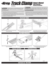
ASSEMBLY
Wheel Assembly
Folding Base
(1) Position the kickstand assembly relative
to the axle supports as shown.
(2) Slide the axle supports onto the axle with
the axle-support anges facing each other.
(3) Slide the wheels onto the axles with the
oset wheel bearings toward the inside.
(4) Thread large ange lock nuts onto the
axles using the included wrenches,
or a ratchet wrench with a 15mm deep
socket and a 15mm combination wrench,
one on each end. Tighten the nuts to a
hard stop.
Set the wheel assembly aside.
(1) Thread foot levelers into leg assembly 1
(the one without folding handles).
(2) Place the Project Table-Top upside down
on a clean and sturdy work surface and
locate the end with two sets of four-holes
in the table top.
(3) Position leg assembly 1 at on the table
top with the folding-brace anchor pates
engaging the four threaded studs
protruding from the table top.
ATTENTION:
!
The folding-brace anchor plates on the two leg
assemblies have different hole patterns and can only be installed in the
proper conguration.
(4) Fasten the upper bar of the leg assembly
to the table top with U-bolts, bar brackets,
and small ange lock nuts, using the
outer pairs of holes. Tighten the nuts
using the included wrenches or a 10mm
deep socket and ratchet wrench.
(5) Push down on the folded braces so they
contact the table top.
(6) Thread small ange lock nuts onto the
brace anchor-plate studs and tighten the
nuts using the included wrenches or a
10mm deep socket and ratchet wrench.
1
3
4
4
4
4
1
2
2
1
1
3
4
4
4
3
2
2
4
5
5
6
6

ASSEMBLY
Folding Base-Continued
(7) Position the wheel assembly with the
axle supports straddling the leg-assembly
upper bar.
(8) Fasten the wheel assembly to the table
top with U-bolts and small ange lock
nuts. Tighten the nuts using the included
wrenches or a 10mm deep socket and
ratchet wrench.
(9) Deploy the kickstand, engaging the
kickstand lock with the axle-brace ange.
(10) Thread foot levelers into leg assembly 2
(the one with handles).
(11) Position leg assembly 2 at on the table top.
(12) Fasten the upper bar of the assembly
to the table top with U-bolts, bar brackets,
and small ange lock nuts. Tighten the
nuts using the included wrenches or a
10mm deep socket and ratchet wrench.
7
10
11
12
12
10
9
8
8
8
8

(12) Slide the retainers into the notches in the brace anchor plates so the slots in the retainers
engage the anchor plates.
(13) Lower the anchor plates with attached retainers onto the protruding studs.
(14) Push down on the folded braces so they contact the table top.
(15) Thread small ange lock nuts onto the brace anchor-plate studs and tighten the nuts using
the included wrenches or a 10mm deep socket and ratchet wrench.
(16) Clip the retainers to the lower leg-assembly bar.
12
12
15
15
16
16
15
13
13
14
14
ASSEMBLY
Folding Base-Continued
(17) Adhere the setup/stow instructions label
to the table top.
(18) Lift the table o the work surface and
stand the folded table upright on the
wheels and kickstand.
17
18
WARNING:
!
Two people are required to lift the Project Table.
15
13

TABLE SETUP
(1) Release the retainers.
(2) Unfold leg assembly 2 (handle end).
(3) Engage the brace locks.
(4) Lower the table, pivoting it on the wheels,
and rest the assembly 2 legs on the ground.
(5) Lower leg assembly 1 (wheel end)
to the ground.
(6) Lift the wheel end by the kickstand.
(7) Fully lower the legs.
(8) Engage the brace locks.
1
3
4
3
1
2
5
8
7
6

TABLE SETUP
TABLE STOW
(9) Disengage the kickstand lock
(10) Pivot the kickstand under the table.
(11) Adjust foot levelers to desired height by
hand, and lock the leveler locknut in
place using a ¾" combination wrench.
(1) Deploy the kickstand engaging the lock.
(2) Release the leg assembly 1 brace locks.
(3) Lift the wheel end of the table by
the kickstand.
(4) Swing legs under the table.
(5) Rest the end of the table on the wheels.
11
10
9
1
3
5
4
2
2

TABLE STOW
(6) Lift the handle end of the table to the
upright position.
(7) Fold leg assembly 1 against the project
table top.
(8) Release the leg assembly 2 brace locks.
(9) Fold leg assembly 2 against the
project table.
(10) Clip the retainers around the bar.
(11) Deploy the handles to move the table.
Store the folded table upright.
6
11
7
9
8
8
10
10
ATTENTION:
!
The Kreg ACS 62" Guide Track (ACS430)
can be stored on the table if desired.

GUIDE TRACK
(1) With the table set up (see Table Setup),
install the star-knob, brass at washer,
and Zinc hex-head bolt and T-knobs
and bolts on the hinge-mounting plates.
(2) Slide the heads of the T-knob bolts into
the T-slot in the table perimeter track.
(3) Position the plate-alignment tabs all the
way to the rear of the table-top notches.
(4) Tighten the T-knobs.
(5) Position the guide track upside down on
the table with the anti-chip strip toward
the center of the table.
(6) Install a cap screw and T-slot nut on the
rst hinge and slide the T-slot nut into the
track outfeed-end T-slot.
ATTENTION:
!
Both hinges are identical and are installed so they
operate in the same direction to raise and lower the guide track.
(7) Position the edge of the hinge 2
1
⁄2" [64mm]
from the end of the track, square it to the
track edge, and tighten the cap screw with
the included hex wrench.
ATTENTION:
!
The 62" guide track (Item # ACS430) is supplied
with the Plunge Saw + Guide Track (item# ACS2000), the Master Kit
(item# ACS3000) or is available separately.
ATTENTION:
!
Before mounting the guide track on the table,
trim the anti-chip strip, following the instructions included in the manual
provided with the Kreg Plunge Saw (item# ACS-SAW).
1
2
1
1
1
1
1
4
4
3
6
5
7
2
1
⁄2"
Anti-chip strip

GUIDE TRACK
(8) Turn the track right side up and orient it
with the anti-chip strip toward the near
edge of the table.
(9) Attach the outfeed-end hinge upright to
the outfeed-end hinge mounting plate
with the star knob and brass at washer.
(10) Raise the hinge upright to the full-up
position and tighten the star knob.
(13) Raise the hinge to the full-up position,
and tighten the star knob.
(14) Lift the track as you shift it toward the
infeed end to fully open both hinges.
(15) Tighten the hinge cap screw with the
included hex wrench.
(11) Install a cap screw and T-slot nut on the
second hinge and slide the nut into the
track infeed-end T-slot. Do not tighten
the screw.
(12) Attach the hinge upright to the
infeed-end mounting plate with the
star-knob and brass at washer.
8
9
12
15
14
12
11
11
13
10
ATTENTION:
!
Make sure both hinges are fully open prior to
tightening the hinge cap screw. This will ensure proper hinge operation.

1
2
ATTENTION:
!
Both Hinge Support Brackets should be installed on
the cut end of the table on each Hinge-Mounting Plate.
HINGE SUPPORT BRACKET INSTALLATION
(1) Remove the T-Knob located on the cut
side of the table.
(2) Insert the Hinge Support Bracket on the
Zinc Hex Head Bolt.
(3) Reinstall the T-Knob and tighten.
(4) Repeat the process for the opposing
Hinge Mounting Plate.
3
/