Page is loading ...

Installation and Operation Manual
X-DPT-DeviceNet-SLA5800-SLAMf-Series-RevB-MFC-eng
Part Number: 541B190AAG
April, 2014
Supplemental Manual for
Brooks
®
DeviceNet™ MFCs/MFMs
For SLA5800 & SLAMf Series

Installation and Operation Manual
X-DPT-DeviceNet-SLA5800-SLAMf-Series-RevB-MFC-eng
Part Number: 541B190AAG
April, 2014
Brooks DeviceNet MFCs/MFMs
Essential Instructions
Read this page before proceeding!
Brooks Instrument designs, manufactures and tests its products to meet many national and international standards. Because
these instruments are sophisticated technical products, you must properly install, use and maintain them to ensure they
continue to operate within their normal specifications. The following instructions must be adhered to and integrated into your
safety program when installing, using and maintaining Brooks Products.
• Read all instructions prior to installing, operating and servicing the product. If this instruction manual is not the correct
manual, please see back cover for local sales office contact information. Save this instruction manual for future reference.
• If you do not understand any of the instructions, contact your Brooks Instrument representative for clarification.
• Follow all warnings, cautions and instructions marked on and supplied with the product.
• Inform and educate your personnel in the proper installation, operation and maintenance of the product.
• Install your equipment as specified in the installation instructions of the appropriate instruction manual and per applicable
local and national codes. Connect all products to the proper electrical and pressure sources.
• To ensure proper performance, use qualified personnel to install, operate, update, program and maintain the product.
• When replacement parts are required, ensure that qualified people use replacement parts specified by Brooks Instrument.
• Unauthorized parts and procedures can affect the product's performance and place the safe operation of your process at
risk. Look-alike substitutions may result in fire, electrical hazards or improper operation.
• Ensure that all equipment doors are closed and protective covers are in place, except when maintenance is being
performed by qualified persons, to prevent electrical shock and personal injury.
ESD (Electrostatic Discharge)
This instrument contains electronic components that are susceptible to damage by electricity. Proper handling
procedures must be observed during the removal, installation, or other handling of internal circuit boards or devices.
Handling Procedure:
1. Power to the unit must be removed.
2. Personnel must be grounded, via a wrist strap or other safe, suitable means before any printed circuit card or other
internal device is installed, removed or adjusted.
3. Printed circuit cards must be transported in a conductive container. Boards must not be removed from protective
enclosure until immediately before installation. Removed boards must immediately be placed in protective container for
transport, storage or return to factory.
Comments:
This instrument is not unique in its content of ESD (electrostatic discharge) sensitive components. Most modern electronic
designs contain components that utilize metal oxide technology (NMOS, SMOS, etc.). Experience has proven that even small
amounts of static electricity can damage or destroy these devices. Damaged components, even though they appear to
function properly, exhibit early failure.

Installation and Operation Manual
X-DPT-DeviceNet-SLA5800-SLAMf-Series-RevB-MFC-eng
Part Number: 541B190AAG
April, 2014
iii
Brooks DeviceNet MFCs/MFMs
Dear Customer,
We recommend that you read this manual in its entirety as this will enable efficient and proper use of the
DeviceNet MFCs/MFMs. Should you require any additional information concerning the DeviceNet MFCs/MFMs,
please feel free to contact your local Brooks Sales and Service Office; see back cover for contact information, or
visit us on the web at www.BrooksInstrument.com. We appreciate this opportunity to service your fluid
measurement and control requirements, and trust that we will be able to provide you with further assistance in
future.
Yours sincerely,
Brooks Instrument

Installation and Operation Manual
X-DPT-DeviceNet-SLA5800-SLAMf-Series-RevB-MFC-eng
Part Number: 541B190AAG
April, 2014
iv
Brooks DeviceNet MFCs/MFMs
THIS PAGE WAS
INTENTIONALLY
LEFT BLANK

Installation and Operation Manual
X-DPT-DeviceNet-SLA5800-SLAMf-Series-RevB-MFC-eng
Part Number: 541B190AAG
April, 2014
v
Contents
Brooks DeviceNet MFCs/MFMs
Contents
1. Introduction .............................................................................................................................................. 1
2. Before Starting ......................................................................................................................................... 3
2.1. Background & Assumptions ...................................................................................................... 3
2.2. Compliance ................................................................................................................................ 3
2.3. Notations .................................................................................................................................... 4
2.3.1. Numbers .................................................................................................................... 4
2.3.2. EPATH ....................................................................................................................... 4
3. Quick Start ................................................................................................................................................ 5
3.1. Step 1: Set Baud Rate and MAC ID .......................................................................................... 5
3.1.1. Baud Rate .................................................................................................................. 5
3.1.2. MAC ID ...................................................................................................................... 6
3.2. Step 2: Configure Scanner ........................................................................................................ 7
3.3. Step 3: Plumb to the Device ...................................................................................................... 9
3.4. Step 4: Connect Device to the Network .................................................................................... 9
3.4.1. Interface Connector ................................................................................................... 9
3.5. Step 5: Apply Power to the Network ........................................................................................ 10
3.6. Step 6: LED Verification .......................................................................................................... 10
3.7. Step 7: Begin Scanning the Network ....................................................................................... 11
3.8. Step 7: Normal Operation ........................................................................................................ 11
4. Configuration ......................................................................................................................................... 13
4.1. Commonly Configured Attributes............................................................................................. 13
4.1.1. I/O Assemblies ........................................................................................................ 14
4.1.2. The “Inferred” Data Type ......................................................................................... 15
4.1.3. Data Type ................................................................................................................ 16
4.1.4. Data Units ................................................................................................................ 17
4.1.4.1. Counts ..................................................................................................... 18
4.1.4.2. Common Device Data Units .................................................................... 18
4.1.5. Safe State (i.e. Safe Mode) ..................................................................................... 19
4.1.5.1. The State Machine and Safe Mode ......................................................... 19
4.1.5.2. Valve Safe Mode ..................................................................................... 20
4.1.5.3. Flow Sensor Safe Mode .......................................................................... 20
4.1.6. Gas Calibration Selection ........................................................................................ 20

Installation and Operation Manual
X-DPT-DeviceNet-SLA5800-SLAMf-Series-RevB-MFC-eng
Part Number: 541B190AAG
April, 2014
vi
Contents
Brooks DeviceNet MFCs/MFMs
5. Detailed Configuration .......................................................................................................................... 23
5.1. Identity Object [0x1] ................................................................................................................. 25
5.1.1. Attributes ................................................................................................................. 25
5.1.1.1. Note: Device Type ................................................................................... 26
5.1.1.2. Note: Revision ......................................................................................... 26
5.1.1.3. Note: Status ............................................................................................. 27
5.1.1.4. Note: Serial Number ................................................................................ 27
5.1.2. Services ................................................................................................................... 28
5.1.2.1. Service Details ......................................................................................... 28
5.1.2.1.1. Reset ....................................................................................... 28
5.2. Message Router Object [0x2] .................................................................................................. 29
5.2.1. Attributes ................................................................................................................. 29
5.2.2. Services ................................................................................................................... 30
5.2.3. Service Details ......................................................................................................... 30
5.3. DeviceNet Object [0x3] ............................................................................................................ 31
5.3.1. Rules Governing Master/Slave Connections........................................................... 31
5.3.2. Attributes ................................................................................................................. 32
5.3.2.1. Note: MAC ID .......................................................................................... 33
5.3.2.2. Note: Baud Rate ...................................................................................... 33
5.3.2.3. Note: MAC ID Switch Changed ............................................................... 34
5.3.2.4. Note: Baud Rate Switch Changed ........................................................... 34
5.3.2.5. Note: BOI ................................................................................................. 34
5.3.2.6. Note: Allocation Information .................................................................... 34
5.3.3. Services ................................................................................................................... 35
5.3.4. Service Details ......................................................................................................... 35
5.3.4.1. Allocate Master/Slave Connection .......................................................... 35
5.3.4.2. Release Master/Slave Connection .......................................................... 36
5.4. Assembly Object [0x4] ............................................................................................................. 37
5.4.1. Services ................................................................................................................... 38
5.4.2. Service Details ......................................................................................................... 38
5.5. Connection Object [0x5] .......................................................................................................... 39
5.5.1. Rules Governing Master/Slave Connections [0x5] .................................................. 39
5.5.2. Attributes ................................................................................................................. 39
5.5.2.1. Explicit Connection Attributes .................................................................. 40
5.5.2.2. Poll I/O Connection Attributes ................................................................. 41
5.5.2.3. Note: State ............................................................................................... 43
5.5.2.4. Note: Transport Class & Trigger .............................................................. 43
5.5.2.5. Note: Initial Comm. Characteristics ......................................................... 44
5.5.2.6. Note: Watchdog Timeout Action .............................................................. 45
5.5.3. Services ................................................................................................................... 45
5.5.4. Service Details ......................................................................................................... 46
5.6. S-Device Supervisor Object [0x30] ......................................................................................... 46

Installation and Operation Manual
X-DPT-DeviceNet-SLA5800-SLAMf-Series-RevB-MFC-eng
Part Number: 541B190AAG
April, 2014
vii
Contents
Brooks DeviceNet MFCs/MFMs
5.6.1. Attributes ................................................................................................................. 46
5.6.1.1. Note: Software Revision Level ................................................................ 50
5.6.1.2. Note: Device Status ................................................................................. 51
5.6.1.3. Note: Exception Status ............................................................................ 51
5.6.1.4. Note: Exception Detail Alarm – Common Exception Detail..................... 52
5.6.1.5. Note: Exception Detail Alarm – Device Exception Detail ........................ 52
5.6.1.6. Note: Exception Detail Alarm – Manufacturer Exception Detail .............. 52
5.6.1.7. Note: Exception Detail Warning – Common Exception Detail ................ 53
5.6.1.8. Note: Exception Detail Warning – Device Exception Detail .................... 53
5.6.1.9. Note: Exception Detail Warning – Manufacturer Exception Detail .......... 53
5.6.2. Services ................................................................................................................... 53
5.6.2.1. Service Details ......................................................................................... 54
5.6.2.1.1. Perform Diagnostics ................................................................ 54
5.7. S-Analog Sensor Object [0x31] ............................................................................................... 55
5.7.1. Attributes ................................................................................................................. 55
5.7.1.1. Note: Data Type ...................................................................................... 58
5.7.1.2. Note: Data Units ...................................................................................... 58
5.7.1.3. Note: Status ............................................................................................. 58
5.7.1.4. Note: Full Scale ....................................................................................... 59
5.7.1.5. Note: Safe State ...................................................................................... 59
5.7.1.6. Note: Gas Calibration Object Instance .................................................... 60
5.7.1.7. Note: Alarms ............................................................................................ 60
5.7.1.8. Note: Warnings ........................................................................................ 60
5.7.1.9. Flow Totalizer and Flow Hours Process .................................................. 61
5.7.2. Services ................................................................................................................... 62
5.7.2.1. Service Details ......................................................................................... 63
5.7.2.1.1. Set Full Scale Counts .............................................................. 63
5.8. S-Analog Actuator Object [0x32] ............................................................................................. 63
5.8.1. Attributes ................................................................................................................. 63
5.8.1.1. Note: Data Type ...................................................................................... 65
5.8.1.2. Note: Data Units ...................................................................................... 65
5.8.1.3. Note: Override ......................................................................................... 66
5.8.1.4. Note: Valve .............................................................................................. 66
5.8.1.5. Note: Status ............................................................................................. 67
5.8.1.6. Note: Safe State ...................................................................................... 67
5.8.1.7. Note: Alarms ............................................................................................ 67
5.8.1.8. Note: Warnings ........................................................................................ 68
5.8.2. Services ................................................................................................................... 68
5.8.2.1. Service Details ......................................................................................... 68
5.9. S-Single Stage Controller Object [0x33] .................................................................................. 69
5.9.1. Attributes ................................................................................................................. 69
5.9.1.1. Note: Data Type ...................................................................................... 72
5.9.1.2. Note: Data Units ...................................................................................... 72
5.9.1.3. Note: Status ............................................................................................. 72
5.9.1.4. Note: Alarms ............................................................................................ 73

Installation and Operation Manual
X-DPT-DeviceNet-SLA5800-SLAMf-Series-RevB-MFC-eng
Part Number: 541B190AAG
April, 2014
viii
Contents
Brooks DeviceNet MFCs/MFMs
5.9.1.5. Note: Warnings ........................................................................................ 73
5.9.1.6. Note: PID Gains ....................................................................................... 73
5.9.2. Services ................................................................................................................... 74
5.9.2.1. Service Details ......................................................................................... 74
5.10. S-Gas Calibration Object [0x34] ............................................................................................ 75
5.10.1. Attributes ............................................................................................................... 75
5.10.1.1. Note: Gas Standard Number ................................................................. 77
5.10.1.2. Note: Gas Correction Factor ................................................................. 77
5.10.1.3. Note: Gas Correction Type .................................................................... 77
5.10.1.4. Note: Customer Full Scale .................................................................... 77
5.10.2. Services ................................................................................................................. 78
5.10.2.1. Service Details ....................................................................................... 78
5.10.2.1.1. Get All Instances ................................................................... 78
6. Troubleshooting .................................................................................................................................... 81
7. Appendix ................................................................................................................................................ 83
7.1. Appendix A - Assembly Object Detail ...................................................................................... 83
7.1.1. Assembly Details ..................................................................................................... 84
7.2. Appendix B - Data Type Definitions ........................................................................................ 92
7.3. Appendix C – Data Units ......................................................................................................... 93
7.4. Appendix D - LED Flash Codes............................................................................................... 96
7.5. Appendix E – Service Summary and Details ........................................................................... 97
7.6. Appendix F - State ................................................................................................................... 98
7.7. Appendix G - EDS Parameter Configuration ......................................................................... 101
7.7.1. Flow Sensor Group ................................................................................................ 102
7.7.1.1. Flow Sensor Safe State Values ............................................................. 102
7.7.2. Valve Group ........................................................................................................... 103
7.7.2.1. Valve Safe State Values ........................................................................ 103
7.7.2.2. Valve Override ....................................................................................... 104
7.7.3. Flow Control Group ............................................................................................... 104
7.7.4. Polled Connection Group ...................................................................................... 105
7.7.5. Device Info Group .................................................................................................. 105
7.7.6. Soft Start (Ramp) Control Group .......................................................................... 106
7.7.7. Alarms/Warnings Group
1
...................................................................................... 106
8. Glossary ............................................................................................................................................... 109

Installation and Operation Manual
X-DPT-DeviceNet-SLA5800-SLAMf-Series-RevB-MFC-eng
Part Number: 541B190AAG
April, 2014
ix
Contents
Brooks DeviceNet MFCs/MFMs
Tables
Table 3-1 I/O Data Description ...................................................................................................................... 7
Table 3-2 *Status ........................................................................................................................................... 8
Table 3-3 **Flow ............................................................................................................................................ 8
Table 3-4 ***Setpoint ..................................................................................................................................... 8
Table 4-1 Commonly Configured Attributes/Parameters............................................................................. 14
Table 4-2 Attributes to Configure Default Assemblies ................................................................................. 15
Table 4-3 Configurable Data Type Attributes .............................................................................................. 17
Table 4-4 Configurable Data Units Attributes .............................................................................................. 17
Table 4-5 Safe State .................................................................................................................................... 20
Table 4-6 Safe Value ................................................................................................................................... 20
Table 5-1 Accessible Classes ..................................................................................................................... 24
Table 5-2 Identity Object Instance 0 Attributes ........................................................................................... 25
Table 5-3 Identity Object Instance 1 Attributes ........................................................................................... 25
Table 5-4 Identity Object [0x1] Status ......................................................................................................... 27
Table 5-5 Identity Object Instance 0 Services ............................................................................................. 28
Table 5-6 Identity Object Instance 1 Services ............................................................................................ 28
Table 5-7 Reset Service Arguments ............................................................................................................ 28
Table 5-8 Reset Service Response ............................................................................................................. 28
Table 5-9 Message Router Instance 0 Attributes ........................................................................................ 29
Table 5-10 Message Router Instance 1 Attributes ...................................................................................... 29
Table 5-11 Message Router Instance 0 Services ....................................................................................... 30
Table 5-12 Message Router Instance 1 Services ....................................................................................... 30
Table 5-13 DeviceNet Object Instance 0 Attributes .................................................................................... 32
Table 5-14 DeviceNet Object Instance 1 Attributes .................................................................................... 32
Table 5-15 Baud Rate Values ..................................................................................................................... 33
Table 5-16 BOI Values ................................................................................................................................ 34
Table 5-17 Allocation Information ................................................................................................................ 34
Table 5-18 DeviceNet Object Instance 0 Services ...................................................................................... 35
Table 5-19 DeviceNet Object Instance 1 Services ...................................................................................... 35
Table 5-20 Allocate Service Arguments ...................................................................................................... 35
Table 5-21 Allocation Choice Byte Values .................................................................................................. 36
Table 5-22 Allocate Service Response ....................................................................................................... 36
Table 5-23 Release Service Arguments ...................................................................................................... 36
Table 5-24 Release Choice Byte Value....................................................................................................... 36
Table 5-25 Release Service Response ....................................................................................................... 36
Table 5-26 Assembly Object Instance 0 Attributes ..................................................................................... 37
Table 5-27 Assembly Object Instance 1..n Attributes ................................................................................. 37
Table 5-28 Assembly Object Instance 0 Services ....................................................................................... 38
Table 5-29 Assembly Object Instance 1..n Services ................................................................................... 38
Table 5-30 Connection Object Instance 0 Attributes ................................................................................... 39
Table 5-31 Instance 1 - M/S Explicit Connection Attributes ........................................................................ 40
Table 5-32 Instance 2 - M/S Polled I/O Connection Attributes .................................................................... 41
Table 5-33 Rules Governing Master/Slave Connections [0x5] ................................................................... 43
Table 5-34 Bit Descriptions ......................................................................................................................... 43
Table 5-35 Direction .................................................................................................................................... 43
Table 5-36 Production Trigger ..................................................................................................................... 43
Table 5-37 Transport Class ......................................................................................................................... 44

Installation and Operation Manual
X-DPT-DeviceNet-SLA5800-SLAMf-Series-RevB-MFC-eng
Part Number: 541B190AAG
April, 2014
x
Contents
Brooks DeviceNet MFCs/MFMs
Table 5-38 Bit Descriptions ......................................................................................................................... 44
Table 5-39 Initial Production Characteristics ............................................................................................... 44
Table 5-40 Initial Consume Characteristics ................................................................................................. 44
Table 5-41 Watchdog Timeout Action ......................................................................................................... 45
Table 5-42 Connection Object Instance 0 Services .................................................................................... 45
Table 5-43 Connection Object Instance 1 Services .................................................................................... 45
Table 5-44 S-Device Supervisor Instance 0 Attributes ................................................................................ 46
Table 5-45 S-Device Supervisor Instance 1 Attributes ................................................................................ 46
Table 5-46 Device Status ............................................................................................................................ 51
Table 5-47 Exception Status ....................................................................................................................... 52
Table 5-48 Alarm – Common Exception Detail ........................................................................................... 52
Table 5-49 Alarm – Device Exception Detail ............................................................................................... 52
Table 5-50 Alarm – Manufacturer Exception Detail ..................................................................................... 52
Table 5-51 Warning – Common Exception Detail ....................................................................................... 53
Table 5-52 Warning – Device Exception Detail ........................................................................................... 53
Table 5-53 Warning – Manufacturer Exception Detail ................................................................................. 53
Table 5-54 S-Device Supervisor Instance 0 Services ................................................................................. 53
Table 5-55 S-Device Supervisor Instance 1 Services ................................................................................. 54
Table 5-56 Diagnostics Service Arguments ................................................................................................ 54
Table 5-57 Test ID ....................................................................................................................................... 54
Table 5-58 Diagnostic Service Response ................................................................................................... 54
Table 5-59 S-Analog Sensor Instance 0 Attributes ..................................................................................... 55
Table 5-60 S-Analog Sensor Instance 1 Attributes ..................................................................................... 55
Table 5-61 Status ........................................................................................................................................ 58
Table 5-62 Full Scale ................................................................................................................................... 59
Table 5-63 Safe State .................................................................................................................................. 59
Table 5-64 S-Analog Sensor Instance 0 Services ....................................................................................... 62
Table 5-65 S-Analog Sensor Instance 1 Services ....................................................................................... 62
Table 5-66 Set Full-Scale Counts Service Arguments ................................................................................ 63
Table 5-67 Set Full-Scale Counts Service Response ................................................................................. 63
Table 5-68 S-Analog Actuator Instance 0 Attributes ................................................................................... 63
Table 5-69 S-Analog Actuator Instance 1 Attributes ................................................................................... 64
Table 5-70 Override ..................................................................................................................................... 66
Table 5-71 Status ........................................................................................................................................ 67
Table 5-72 Safe State .................................................................................................................................. 67
Table 5-73 S-Analog Actuator Instance 0 Services ..................................................................................... 68
Table 5-74 S-Analog Actuator Instance 1 Services ..................................................................................... 68
Table 5-75 S-Single Stage Controller Instance 0 Attributes ........................................................................ 69
Table 5-76 S-Single Stage Controller Instance 1 Attributes ........................................................................ 70
Table 5-77 Status ........................................................................................................................................ 72
Table 5-78 S-Single Stage Controller Instance 0 Services ......................................................................... 74
Table 5-79 S-Single Stage Controller Instance 1 Services ......................................................................... 74
Table 5-80 S-Gas Calibration Instance 0 Attributes .................................................................................... 75
Table 5-81 S-Gas Calibration Instance 1..n Attributes ................................................................................ 75
Table 5-82 Gas Correction Type ................................................................................................................. 77
Table 5-83 S-Gas Calibration Instance 0 Services ..................................................................................... 78
Table 5-84 S-Gas Calibration Instance 1..n Services ................................................................................. 78
Table 5-85 Get All Instances Arguments ..................................................................................................... 78
Table 5-86 Get All Instances Response ...................................................................................................... 79
Table 7-1 Summary Table of Input Assemblies .......................................................................................... 83

Installation and Operation Manual
X-DPT-DeviceNet-SLA5800-SLAMf-Series-RevB-MFC-eng
Part Number: 541B190AAG
April, 2014
xi
Contents
Brooks DeviceNet MFCs/MFMs
Table 7-2 Summary Table of Output Assemblies ........................................................................................ 83
Table 7-3 Input Assembly 1 ......................................................................................................................... 84
Table 7-4 Input Assembly 2 ......................................................................................................................... 84
Table 7-5 Input Assembly 3 ......................................................................................................................... 84
Table 7-6 Input Assembly 4 ......................................................................................................................... 85
Table 7-7 Input Assembly 5 ......................................................................................................................... 85
Table 7-8 Input Assembly 6 ......................................................................................................................... 86
Table 7-9 Output Assembly 7 ...................................................................................................................... 86
Table 7-10 Output Assembly 8 .................................................................................................................... 86
Table 7-11 Input Assembly 13 ..................................................................................................................... 87
Table 7-12 Input Assembly 14 ..................................................................................................................... 87
Table 7-13 Input Assembly 15 ..................................................................................................................... 88
Table 7-14 Input Assembly 16 ..................................................................................................................... 88
Table 7-15 Input Assembly 17 ..................................................................................................................... 89
Table 7-16 Input Assembly 18 ..................................................................................................................... 90
Table 7-17 Output Assembly 19 .................................................................................................................. 91
Table 7-18 Output Assembly 20 .................................................................................................................. 91
Table 7-19 Data Types ................................................................................................................................ 92
Table 7-20 Volumetric Flow Units ................................................................................................................ 93
Table 7-21 Mass Flow Units ........................................................................................................................ 95
Table 7-22 Actuator Units ............................................................................................................................ 95
Table 7-23 NET LED Flash Codes .............................................................................................................. 96
Table 7-24 MOD LED Flash Codes ............................................................................................................. 96
Table 7-25 Get Attribute Single Service Parameters .................................................................................. 97
Table 7-26 Success Response Data ........................................................................................................... 97
Table 7-27 Set Attribute Single Service Parameters ................................................................................... 97
Table 7-28 Success Response Data ........................................................................................................... 97
Table 7-29 S-Device Supervisor State Event Matrix ................................................................................... 99
Table 7-30 Parameter Groups ................................................................................................................... 101
Table 7-31 Supported Flow Sensor Parameters ....................................................................................... 102
Table 7-32 Flow Sensor Safe State Values .............................................................................................. 102
Table 7-33 Supported Valve Parameters .................................................................................................. 103
Table 7-34 Valve Safe State Values .......................................................................................................... 103
Table 7-35 Valve Override Values ............................................................................................................. 104
Table 7-36 Supported Flow Control Parameters ....................................................................................... 104
Table 7-37 Polled Connection Values ....................................................................................................... 105
Table 7-38 Supported Device Info Parameters ......................................................................................... 105
Table 7-39 Supported Soft Start Parameters ............................................................................................ 106
Table 7-40 Alarms/Warnings ..................................................................................................................... 106
Figures
Figure 3-1 Baud Rate Switch ......................................................................................................................... 5
Figure 3-2 MAC ID Switches ......................................................................................................................... 6
Figure 3-3 Interface Connector ...................................................................................................................... 9
Figure 3-4 View Showing Top of MFC/MFM Can ........................................................................................ 10
Figure 7-1 S-Device Supervisor State Machine Diagram............................................................................ 98

Installation and Operation Manual
X-DPT-DeviceNet-SLA5800-SLAMf-Series-RevB-MFC-eng
Part Number: 541B190AAG
April, 2014
xii
Contents
Brooks DeviceNet MFCs/MFMs
THIS PAGE WAS
INTENTIONALLY
LEFT BLANK

Installation and Operation Manual
X-DPT-DeviceNet-SLA5800-SLAMf-Series-RevB-MFC-eng
Part Number: 541B190AAG
April, 2014
1
Section 1
-
Introduction
Brooks DeviceNet MFCs/MFMs
1. Introduction
Many applications of Flow Meters/Controllers and Pressure devices are
moving to increasing the use of automation. Automation comes in many
forms: PLC’s (Programmable Logic Controllers), DCS’s (Distributed Control
Systems), and PC-based solutions. Digital communications from these varied
automation systems and the devices they measure and control are a very
effective means of not only accomplishing more effective and rapid system
integration, but also providing greatly improved system diagnostics and
maintainability. DeviceNet™
is an open digital protocol capable of high
speeds and easy system connectivity. Brooks Instrument has several of its
devices available on this popular networking standard, and is a member of
ODVA™ (Open DeviceNet Vendors Association), the governing standard
body for DeviceNet.

Installation and Operation Manual
X-DPT-DeviceNet-SLA5800-SLAMf-Series-RevB-MFC-eng
Part Number: 541B190AAG
April, 2014
2
Section 1
-
Introduction
Brooks DeviceNet MFCs/MFMs
THIS PAGE WAS
INTENTIONALLY
LEFT BLANK

Installation and Operation Manual
X-DPT-DeviceNet-SLA5800-SLAMf-Series-RevB-MFC-eng
Part Number: 541B190AAG
April, 2014
3
Section 2
-
Before Starting
Brooks DeviceNet MFCs/MFMs
2. Before Starting
2.1. Background & Assumptions
This manual is a supplement to the SLA5800 Series Mass Flow Controller
Operation Manual. It is assumed that the owner of this SLA5800 Series MFC
is thoroughly familiar with the theory and operation of a SLA5800 Series
MFC/ MFM. If not, it is recommended that the owner read the Operations
Manual first before continuing with this supplement.
This manual assumes a basic knowledge and understanding of the
DeviceNet protocol, its topology and its method of logically accessing the
data or parameters contained within a device. This manual also assumes
basic knowledge and understanding regarding the operation of Mass Flow
Controllers or Mass Flow Meters. This manual is not intended to be a
replacement to the ODVA (Open DeviceNet Vendors Association)
specification, which is still the authoritative definition and description of
DeviceNet communications. It is recommended, but not required for the
purposes of this manual, that the user obtain a copy of the DeviceNet
specification from ODVA
(http://www.odva.org/).
This manual does not make any assumptions about any particular
manufacturer of equipment or custom software used by the user to
communicate with the Brooks device, but assumes the user has thorough
understanding of such equipment and any configuration software.
2.2. Compliance
The SLA5800 Series Mass Flow Controller (MFC) or Mass Flow Meter
(MFM) conforms to the ODVA specified Device Profile for a Mass Flow
Controller device (see: ODVA Specification Volume 1, Section 6-31). The
SLA5800 Series MFC/MFM device has been operationally certified by ODVA
at the Conformance Test Lab in Ann Arbor, Michigan. The test verified that
the device conforms to all specifications required of a DeviceNet capable
device, the Mass Flow Controller Profile (0x1A) and its supporting objects.
Additionally the Mass Flow Controller and Mass Flow Meter devices have
been certified through ODVA to conform to the Semiconductor Special
Interest Groups (Semi-Sig) standards and tests.

Installation and Operation Manual
X-DPT-DeviceNet-SLA5800-SLAMf-Series-RevB-MFC-eng
Part Number: 541B190AAG
April, 2014
4
Section 2
-
Before Starting
Brooks DeviceNet MFCs/MFMs
2.3. Notations
This section details notations and conventions used throughout the manual.
It is recommended that the reader become very familiar with these
conventions. Hypertext links are used in the manual to assist in navigating.
This manual is best viewed in its electronic form and can be obtained from
the Brooks Customer Service Department (Flow Meter, Flow Controller,
Level Measurement Documentation) in Adobe
®
Acrobat
®
PDF format. A
glossary is provided for reference in Section: 8 Glossary to aid in reviewing
and/or to define any unfamiliar terms.
2.3.1. Numbers
Numeric values used throughout this manual will be clearly denoted as to the
base numeric system it represents. All hexadecimal numbers (base 16) will
be prefixed with a 0x, like 0xA4. All binary numbers (base 2) will be suffixed
with a b, like 1001b. All other numbers not annotated this way will be
assumed decimal (base 10).
2.3.2. EPATH
EPATH’s will be denoted within brackets [], like [0x31, 1, 3], which
represents, left to right, the Class ID (hexadecimal), Instance ID (decimal),
and Attribute ID (decimal).

Installation and Operation Manual
X-DPT-DeviceNet-SLA5800-SLAMf-Series-RevB-MFC-eng
Part Number: 541B190AAG
April, 2014
5
Section 3
-
Quick Start
Brooks DeviceNet MFCs/MFMs
3. Quick Start
This section assumes the owner of the SLA5800 Series device has a fully
operational and trouble-free communications network with appropriate power
supplies as defined in the DeviceNet specification. This section also
assumes that there exists, connected to the network, a “master” type of
device with Poll I/O scanning capability (generally this is the most common
application for a DeviceNet network).
3.1. Step 1: Set Baud Rate and MAC ID
Two sets of switches are provided for setting the communication baud rate
and for setting the MAC ID of the device. The default MAC-ID is 63. Set
these switches on the MFC(s) to the desired values.
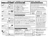
3.1.1. Baud Rate
The switch labeled “RATE” sets the baud rate of the MFC. Possible values
along with their corresponding label are (see figure below): “1” = 125K baud,
“2” = 250K baud, and “5” = 500K baud, “P” = Software programmable where
DeviceNet communications may be used to set the baud rate to one of the
above values. The out-of-box default setting is 500K baud.
Figure 3-1 Baud Rate Switch

Installation and Operation Manual
X-DPT-DeviceNet-SLA5800-SLAMf-Series-RevB-MFC-eng
Part Number: 541B190AAG
April, 2014
6
Section 3
-
Quick Start
Brooks DeviceNet MFCs/MFMs
3.1.2. MAC ID
Two switches labeled with “ADDRESS” are used to configure the MAC ID of
the device. MAC ID stands for Media Access Control Identifier and is used to
set the unique address of the device on the network. The possible range of
addresses is 00 to 63
1
.
The switch labeled “MSD” is used to set the most significant digit of the
address: 00, 10, 20, 30, …, etc., up to 60. If “MSD” is set in the range labeled
as “P” this indicates the MAC ID of the device is software programmable and
must be set through the network.
The switch labeled “LSD’ sets the least significant digit of the MAC ID. The
out-of-box default setting for the MAC ID is 63.
Figure 3-2 MAC ID Switches
NOTE:
Any changes made to the MAC ID or Baud Rate values, either by externally
setting them or through software, will not take effect until the device has been
power cycled.
1
MAC ID 63 is reserved by ODVA as a commissioning node address and should not be used operationally during the execution of a process.

Installation and Operation Manual
X-DPT-DeviceNet-SLA5800-SLAMf-Series-RevB-MFC-eng
Part Number: 541B190AAG
April, 2014
7
Section 3
-
Quick Start
Brooks DeviceNet MFCs/MFMs
3.2. Step 2: Configure Scanner
This section contains information that will be needed to configure the
scanning device (e.g. PLC, PC, DCS). You will need to consult the
documentation for these systems for proper configuration to the device
configuration information below.
The SLA5800 Series MFC/MFM comes from the factory with a default
configuration as defined by the MFC/MFM Device Profile. The table below
lists attributes that are of the most interest to owners of this type of device
and the factory configured default values. For more information on all the
supported attributes in the device, see Section 5: Detailed Configuration.
NOTE:
If you ordered your SLA5800 Series MFC/MFM and requested that the
Factory pre-configure the device per your own custom specification, the
following tables may not apply.
The default assemblies used for Poll I/O communications.
Table 3-1 I/O Data Description
Input Assembly Output Assembly
Assembly
Instance
2 7
Data Size 3 bytes 2 bytes
Assembly Type Input Output
Definition of Bytes
Byte 0 Status* Byte 0 Setpoint***
Byte 1
Flow**
Byte 1
Byte 2 N/A
Status is defined as an 8-bit bitfield whose bits have the following definition.

Installation and Operation Manual
X-DPT-DeviceNet-SLA5800-SLAMf-Series-RevB-MFC-eng
Part Number: 541B190AAG
April, 2014
8
Section 3
-
Quick Start
Brooks DeviceNet MFCs/MFMs
Table 3-2 *Status
Bit Description
0 Common Alarms
1 Device Profile Specific Alarms
2 Manufacturer Specific Alarms
3 0
4 Common Warnings
5 Device Profile Specific Warnings
6 Manufacturer Specific Warnings
7 1 (Extended Reporting Enabled)
Flow is defined as a 16-bit signed integer (-32768 to 32767) to represent flow
in data units of counts
1
.
The numeric range definitions for Flow are:
Table 3-3 **Flow
Counts
Range < 0 0 - 24576 24577 - 27033 27034 - 32767
Flow Reverse
Flow
0% to 100%
of Full Scale
100+% to 110%
of Full Scale
110+% to 133% of
Full Scale
Setpoint is defined as a 16-bit signed integer (-32768 to 32767) to represent
the setpoint value in data units of counts
1
.
The numeric range definitions for Setpoint are:
Table 3-4 ***Setpoint
Counts
Range < 0 0 – 24576 24577 -27033 27034 - 32767
Setpoint Not Valid. The minimum
value for setpoint will be
clamped to 0% of Full
Scale
0% to 100%of
Full Scale
100+% to
110% of Full
Scale
Not Valid. The maximum
value for setpoint will be
clamped to 110% of Full
Scale
1
The Data Units Counts is a dimensionless unit that defines a range of numbers to represent a quantity. See Configuration Section for more
information on Data Units counts.
1
The Data Units Counts is a dimensionless unit that defines a range of numbers to represent a quantity. See Configuration Section for more
information on Data Units counts.
/